Installation P/N 73-200-8501, Rev. B, 12/09/2020 Page 3of 4
DO NOT plug a Jet Pump or Higher Rated Circulation Pump into this circuit, otherwise the circuit will overheat and burn up,
which voids the warranty.
Circulation Pump wiring: The circulation pump cord will have 3 wires (cord is not included, sold separately). The Black wire is for Line
1. The White wire is for Common connection, and the Green wire is for Ground. Connect the circulation pump cord in the Circulation
Pump location (J47) on the circuit board. The plug will only fit one way. Make sure the clip on the plug latches to ensure tight connection.
Only connect the circulation pump cord if it is being used. (See notes above regarding the circulation pump circuit and using a
circulation pump with this system)
Dip Switch Settings: The dip switches on the circuit board (as known as Switch Bank A, red in color with white switches) should have
already been configured for the correct setting based on your order for Factory Configuration. If a different setup is made in the field
and/or a circulation pump is added, the dip switches need to be reconfigured. If so, please follow the dip switch settings based on the new
setup by using the wiring diagram as a reference, which is required for Field Configuration.
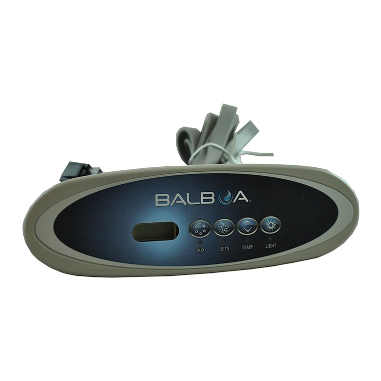
Topside Panel Installation: A hole cut out of 3.75 inch x 1.0 inch is required for the Balboa VL200 Model Topside Panel. A topside
cover plate (included) may be used if the existing hole cut out is larger than the new topside panel. Clean the surface area before
installation of the new topside panel. Position the topside panel in the direction for operational purpose as desired. Then carefully insert
the topside cable through the hole cut out. Remove the protective label from the sticky gasket on the back of the topside panel. Then apply
the topside panel above the hole cut out or cover plate. Silicone can be used under the lip of the topside panel and/or topside cover plate
for additional water leak protection prior to installation of the topside panel. Connect the topside cable plug into J1 connector on the
circuit board. The clip on the topside cable plug should snap in place to ensure a secure connection. The J2 connector is for a secondary
topside panel, which can be purchased separately. If a longer topside cable is needed, do not splice the cable for it will void the topside
warranty. Available at www.spaguts.com is P/N 30311 for the 10ft extension cable, and P/N 22639 for the 25ft extension cable. Maximum
cable length is 50ft in order for the topside panel to work properly.
Light wiring: The light harness is 8ft long with 2 wires. One end of the light harness has a 2-prong amp plug, and the other end has a
light socket that fits a 12V 12W light bulb or a ColorGlo Led Light (http://www.spaguts.com/Products/colorglo-led-lights-47.aspx).
Connect the 2-prong amp plug in location (J20) on the circuit board. The plug will only fit one way. Make sure the clip on the plug latches
to ensure tight connection. Insert the light bulb into the light socket. Then insert the light socket with light bulb into the existing light
housing on the spa. If a light housing is not installed, it can be purchased by going to this link: http://www.spaguts.com/Products/thru-
shell-light-lense-kit-88.aspx. The light circuit is rated 12V 1A Max. Only connect the light harness if it is being used.
Audio Video wiring (A/V): The A/V circuit is normally setup for 110V (unless it was specified over the phone at the time of order for
220V output). This circuit is a constant voltage output normally used for a stereo, radio, CD or TV systems. The A/V cord will have 3
wires (cord is not included, sold separately). The Black wire is for Line 1. The White wire is for Common connection, and the Green wire
is for Ground. Connect the A/V cord in the A/V location (J50) on the circuit board. The plug will only fit one way. Make sure the clip on
the plug latches to ensure tight connection. The A/V circuit is rated 2A Max. Only connect the A/V cord if it is being used.
DO NOT POWER UP THE SPA UNLESS THE SYSTEM IS COMPLETELY INSTALLED AND THE SPA IS COMPLETELY
FILLED UP WITH WATER. Doing so can cause a dry fire, which can damage the heater and controller, and will void the
warranty.
After installation is complete, completely fill the spa with water to the required level. Refer to the Spa Owners Manual for the required
water level. We recommend using a Spa Pre-Filter for fresh clean water. DO NOT OVERFILL. Overflowing the spa will cause water to
infiltrate the system and other electrical parts. Damages caused by water infiltration will not be covered under warranty. Once the spa is
completely filled to the required level, then power up the spa and purge the water lines to help remove air from the lines. The “Pr”
message will appear on the topside panel which indicates water purging is required or is in progress. If the pump is not running, press on
the Jets key to activate the pump on high speed. You may also bleed air out of the plumbing by loosening the plumbing fittings a bit, and
then run the pump high speed on/off until all the air is removed. Once there is constant strong water pressure from the jets, you can now
proceed with normal operations. Make sure all plumbing fittings are tightened, and to fix any water leak.
System Maintenance: It is recommended to monitor the spa equipment every month. Check for any water leaks, internally and
externally, and for abnormal operations. Get it repaired right away if there is a problem. Don't allow the problem to get worst. It is
recommended to inspect for any loose connections and for any damaged cables every 3-6 months (especially on the power terminal block,
component cord, and sensors). Loose connections will cause improper operation and overheat the wires. Damaged cables may also be
chewed by rodents. Neglect of maintenance and damages are not covered under warranty.
Spa Maintenance: Refer to the Original Spa Owners Guide for proper water maintenance. Use ONLY Spa rated chemicals. We
recommend using ozone, Mineral Cartridges and a small amount of chemical to treat the water (may depend on usage). Ozone and
Mineral Cartridges reduces maintenance and decreases the use of chemicals up to 90%. We also recommend to test the spa water every
single day, and treat the spa water as needed. Your local dealer is familiar with local water conditions and which chemicals are compatible
with the water and are designed specifically for your spa. This is the best person to advise you on proper water quality management.
The one thing you can do to insure years of trouble free equipment operation is to maintain proper water chemistry.
Two basic goals of the chemical water treatment are sanitizing and balancing the water.
Sanitizing simply means keeping water free from living micro-organisims including algae, bacteria, and viruses. The current most popular
chemicals for sanitizing include chlorine, bromine, and ozone.


