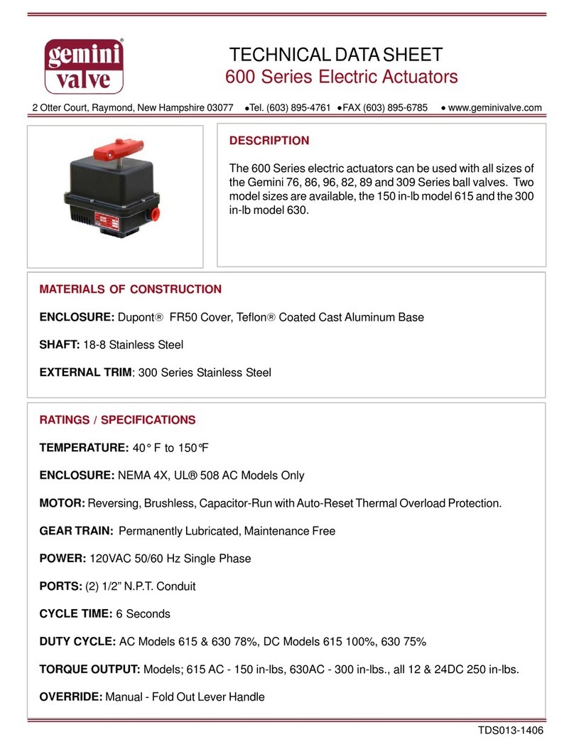
Gemini Valve A500 Series Instruction Manual

2 Otter Court, Raymond, New Hampshire 03077 Tel. (603) 895-4761 FAX (603) 895-6785 www.geminivalve.com
TECHNICALDATASHEET
A500 Series Pneumatic Actuators
MATERIALS OF CONSTRUCTION
BODY: Aluminium withTeflon®ImprenatedHardAnodized(PolyLube®) Sufaces
EXTERNAL HARDWARE: (Pinion Shaft, Driver, End Caps) 300 Series Stainless Steel
SPRING MODULES: A512SRZytel ® Housing,A522SR AluminiumwithTeflon®Imprenated
HardAnodized(PolyLube®) Sufaces, 300 StainlessHardware
EXTERNAL TRIM: 300 Series Stainless Steel
RATINGS / SPECIFICATIONS
TEMPERATURE: -20 F to 350 F
POWER: 50- 125 psiair. Sufficientairdeliverymustbe available at the actuator toensuredepend-
ableoperation. Thefollowing precautionsshouldbeobserved: Airsupplyshouldbecleanand freeof
moisture. When dirty or wet air is a problem; a filter / separator should be specified; these units are
most effectivewheninstalledas closelyaspossibleto theactuator. Afilter, whenused,shouldpermit
aminimumflowof4scfmatanupstreampressureof 60 psi. Eliminate severe restrictions to air flow
(certainsolenoidvalves& fittings). The most restricted passagemusthavean area no smallerthan
.012inchessquare, the area of1/8” diameterorifice. Ifmorethanasingle actuator istobesupplied
byanindividualpilot,theminimumpassagerequirement appliesperactuator.
TUBING: For short runs up to 5 feet 5/32” I.D. is suitable, 1/4” I.D. will serve up to 30 feet. For
longerruns,use3/8” I.D.orlarger.
DESCRIPTION
500Seriespneumaticactuatorsarethelatestin compact rack
andpinionvalve automationfromGeminiValve.TheA500fea-
tures 50 psi operation on all models and sizes and includes
manyindustrystandardsfeaturessuchasNAMURinterfaces
andISOmounting options.
TDS009-0710

RATINGS / SPECIFICATIONS (continued)
DUTY CYCLE: 100%
CYCLE TIME: (To Open or Close)Approximately 1/2 to 1 second*
* - Dependent upon actuator model,airpressureand delivery
TORQUE OUTPUT
MAINTENANCE
Gemini A500 Series Pneumatic Actuators are designed to be maintenance free and normally are replaced
vs. repaired.
Double-Acting Models: For double-acting models, rebuilding of the actuator by our Factory Authorized
Service Center may enable the actuator to be returned to service depending on the duty cycle the actuator
has seen. The cost to rebuild the actuator is generally 50% of the cost of a new actuator. For details on this
service please contact us. Additionally, for those customer desiring to replace 0-rings, gasket(s) and lubri-
cant, we offer o-ring kits which contain these genuine factory components.
Spring-Return Models: For the A500 Series spring-return models, rebuilding of the actuator by our Fac-
tory Authorized Service Center may enable the actuator to be returned to service depending on the duty
cycle the actuator has seen. The cost to rebuild the actuator is generally 50% of the cost of a new actuator.
For details on this service please contact us. O-rings kits are not available for theA500 Series Spring Return
models.
Torque Output - in. - lbs.*
CAUTION: Care must be taken to assure the output torque of theA500 SeriesActuator selected is adequate
toturn thevalve ordevice tobe operated. Note:Does notapply formounting ofGemini Valves toA500 Series
Actuators. Gemini Valve offers a selection chart for your convenience. See our literature for details. Note
also; special sizing considerations should be given when a valve is handling suspended solids, abrasives,
dirty media, oxygen and dry gasses.
*-Approximate

ACTUATOR TO VALVE MOUNTING INSTRUCTIONS
76, 82, 86 & 96 SERIES VALVES
Theseinstructions detailthe procedurefor installinga GeminiA500Series actuatoron adrive-keyequipped Gemini
76,82, 86& 96Series ballvalve. Valvesmay bepurchased withthe drive-keyassembled ormay beretrofitted with
a drive-key conversion kit.
Instructions:
Assemble Bracket toActuator
1. Positionthe actuator uprightwith
driver and the A & B ports oriented
as shown in Figure 1.
2. With the counter sunk holes ex-
posed, position the bracket to
achieve an inline or cross mounted
actuator orientation as described
below. Table 1 lists the valve condi-
tion at rest with respect to the Ac-
tuator Model # (See actuator name-
plate to determine model number
a. Inline- (standard mounting for
mostactuators) The longaxisof the
actuator is in-line with the piping.
Thebracket should beoriented per-
pendicular to the actuator body.
(See Figure 2)
b.Cross mounted- the long axis of
the actuator is perpendicular to the
piping. The bracket should be
mounted parallel to the actuator
body. (See Figure 3)
3. Install the 4 hex flat socket head
mounting screws to (60 inches lbs. for
A510 and 75 inch lbs. for A520 actuators)
securebracket tothe actuatorbody.
Important:Toensurepositive fasten-
ing mounting screws and bracket
counter sunk holes must be clean
and dry. Figure 3
Table 1
Figure 1
Figure 2
ledoMrotautcAdetnuoMtseRtanoitidnoCevlaV
ON215AenilnInepO
ON215AtnuoMssorCdesolC
215AenilnIdesolC
215AtnuoMssorCnep
O
ON225AenilnInepO
ON225AtnuoMssorCdesolC
225AenilnIdesolC
225AtnuoMssorCnepO

ACTUATOR TO VALVE MOUNTING INSTRUCTIONS
76, 82, 86 & 96 SERIES VALVES(continued)
Assemble Valve toActuator
IMPORTANTNotethe redOPEN/
SHUTindicator mountedontop of
theactuator shaftand theposition
ofthe ballin thevalve. Theactua-
tor should be mounted such that
the red indicator is in-line with the
valve body when the ball is in the
openposition,or acrossthe valve
bodywhen theballis inthe closed
position.
1. Rotate the valve stem so that it
is in the corresponding closed or
open position with regards to the
actuator. The drive key on the
valve should be perpendicular to
valvebodywhenvalveisopenand
parallel when in the closed posi-
tion.
2. Confirm proper position of the
locator screws on the bottom of
thebracket basedon the sizeand
seriesof thevalve beingmounted
as Listed in Table 2.
3. Place the actuator, with the
bracket attached, atop the valve
so that the 12 point socket en-
gages the stem nut, the shaft
notch engages the drive-key and
locator screws straddle the valve
body hex (see Figure 4). If the lo-
catorscrewsdonotspan thevalve
properly (i.e. interfere with eye-
browsordonot engagevalve) turn
valve 180 degrees.
4. Positionthevalveretainingstrap
over the valve and align with
bracket holes. Secure strap with
two hex head cap screws. Alter-
nate tightening the strap bolts to
obtain even tension on the strap
andtoavoid skewing. Donotover
tighten. A gap should remain be-
tween strap and bracket when
Figure 4
Table 2
Actuator
Series Valve Size & Series Locator Screw
Mounting
Pattern
A510
76 82 86 96
1/2 1/4, 3/8, 1/2 1/4 & 3/8 - 1
3/4 3/4 1/2 - 2
113/41/2 3
1-1/4 - 1 3/4 4
A520
1-1/4 - 1 3/4 4
1-1/2 - 1-1/4 1 5
2 - 1-1/2 1-1/4 6
--21-1/27

ACTUATOR TO VALVE MOUNTING INSTRUCTIONS
89 SERIES VALVES
These instructions detail the procedure for installing a GeminiA500 Series actuator on a drive-key equipped
Gemini 89 Series ball valve.
Instructions:
Assemble Bracket to Actuator
1. Position the actuator upright with
driver and the A & B ports oriented
as shown in Figure 1.
2. With the counter sunk holes ex-
posed, position the bracket to
achieve an inline or cross mounted
actuator orientation as described
below. Table 1 lists the valve condi-
tion at rest with respect to the Ac-
tuator Model # (See actuator name-
plate to determine model number).
a. Inline- (standard mounting for
mostactuators) The longaxisof the
actuator is in-line with the piping.
Thebracket should beoriented per-
pendicular to the actuator body.
(See Figure 2)
b. Cross mounted- the long axis of
the actuator is perpendicular to the
piping. The bracket should be
mounted parallel to the actuator
body. (See Figure 3)
3. Install the 2 hex flat socket head
mounting screws to (60 inches lbs. for
A510 and 75 inch lbs. for A520 actuators)
securebracket tothe actuatorbody.
Important: To ensure positive fas-
tening, mounting screws and
bracket counter sunk holes must be
clean and dry.
Figure 1
Figure 2 Figure 3
Table 1
ledoMrotautcAdetnuoMtseRtanoitidnoCevlaV
ON215AenilnInepO
ON215AtnuoMssorCdesolC
215AenilnIdesolC
215AtnuoMssorCnep
O
ON225AenilnInepO
ON225AtnuoMssorCdesolC
225AenilnIdesolC
225AtnuoMssorCnepO

ACTUATOR TO VALVE MOUNTING INSTRUCTIONS
89 SERIES VALVES (continued)
Assemble Valve toActuator
IMPORTANT! Notethe redOPEN/
SHUTindicator mountedontop of
theactuator shaftand theposition
ofthe ballin thevalve. Theactua-
tor should be mounted such that
the red indicator is in-line with the
valve body when the ball is in the
openposition,or acrossthe valve
bodywhen theballis inthe closed
position.
1. Rotate the valve stem so that it
is in the corresponding closed or
open position with regards to the
actuator. The drive key on the
valve should be perpendicular to
valvebodywhenvalveisopenand
parallel when in the closed posi-
tion.
2. Place the actuator, with the
bracket attached, atop the valve
so that the 12 point socket en-
gages the stem nut, the shaft
notch engages the drive-key and
locator screws straddle the valve
body hex (see Figure 4).
3. Install two socket head cap
screws to secure valve to mount-
ing bracket.
Figure 4

ACTUATOR TO VALVE SELECTION DATA
Actuator Models
Suitable for
Valve Series & Size
76 82 86 96 89
(Port) 309
A512D (Double-Acting)
A512SR (Spring-Return)
1/2 1/4 & 3/8 1/4& 3/8 - 0.5 1/2
3/4 1/2 1/2 - 0.6 3/4
1 3/4 3/4 1/2 0.8 -
1-1/4 1 1 3/4 - -
A522D (Double-Acting)
A522SR (Spring-Return)
1-1/2 - 1-1/4 1 1.0 -
2 - 1-1/2 1-1/4 1.2 -
--21-1/21.5-

DIMENSIONS
76, 86 & 96 SERIES VALVES
Valve Size & Series Actuator
Model Approximate Dimensions, Inches
76 86 96 Spring
Return Double
Acting ABB1CDEFGH I JKLMN
76 86/96
1/2 1/4 & 3/8 -
A512SR A512D 1.36 1.00 1.53 .31 3.06 4.67
3.88
.32 3.00
1.00 2.18 2.18
3.62 8.31 2.81 .57
3/4 1/2 - 4.06 1.18 2.22 2.61
1 3/4 1/2 4.38 1.50 2.76 2.94
1-1/4 1 3/4 6.44 2.00 3.02 3.32
1-1/2 1-1/4 1
A522SR A522D 1.87 1.55 2.25 .50 4.50 5.18
7.59
1.10 4.75
2.12 3.45 3.70
5.28 11.23 3.50 .822 1-1/2 1-1/4 8.09 2.62 4.04 4.25
- 2 1-1/2 8.47 3.00 - 4.57
309 SERIES VALVES
&eziSevlaV
seireS
rotautcA
ledoM sehcnI,snoisnemietamixorppA
903 gnirpS
nruteR
elbuo
gnitcA AB 1BC EFGHa-Ib-IJKLMN
2/1
RS215A215A63.100.135.113.60.376.477.523.36.155.100.258.326.313.818.275.
4/3

DIMENSIONS
89 SERIES VALVES
82 SERIES VALVES
Tube
Size Actuator Model Approximate Dimensions - Inches
Spring Return Double Acting A B B1 C D E F G H I J K L M N O
1/4
A512SR A512D 1.46 1.00 1.53 .31 3.06 4.67
4.51
.32 3.00
1.00 3.72
3.62 8.31 2.81 .57
9/16
3/8 4.51 1.00 3.70 11/16
1/2 4.61 1.00 3.94 7/8
3/4 4.91 1.19 4.17 1-1/8
1 5.37 1.50 4.92 1-1/2
This manual suits for next models
4
Table of contents
Other Gemini Valve Controllers manuals
Popular Controllers manuals by other brands

National Instruments
National Instruments NI cRIO-9065 Getting started guide

Kutai electronics
Kutai electronics EA16 Operation manual

Estun
Estun TRIO Flex-6 Nano user manual

Jung
Jung Smart Control IP Commissioning

Carel
Carel EVD4 user manual

Johnson Controls
Johnson Controls PENN P70AB-2 Installation Sheets Manual