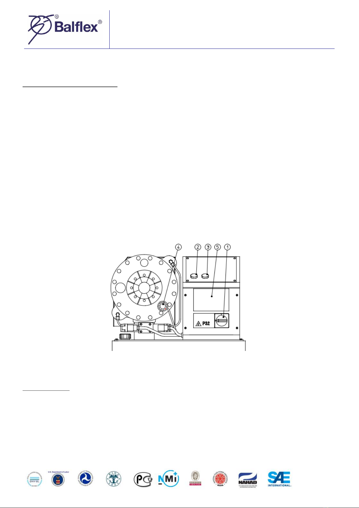
Balflex P20 User manual

OPERATION MANUAL
P20
MANUFACTURING YEAR
SERIAL NUMBER
P32
MANUFACTURING YEAR
SERIAL NUMBER

P20 / P32 OPERATIONS MANUAL
Page | 1
CONTENTS
CONTENTS
1
GENERAL
2
TRANSPORT
2
MOUNTING
3
DISPOSAL OF THE PACKING MATERIAL
4
WARNINGS
4
COMISSIONING
6
Oil Fill
6
Electrical Connection
6
OPERATION
7
Control Identification
7
Steps of Crimping
7
TEST RUN
9
SELECTING THE DIE SET P20
9
SELECTING THE DIE SET P32
10
INSTALLING THE DIE SET
11
Quick Change
11
Change of a single die P20, P32
11
SETTING THE CRIMPING DIAMETER MS
12
CRIMPING MS CONTROL
13
PREVENTIVE MAINTENANCE
14
Greasing P20, P32
14
Oil Change
15
Filter Change P20. P32
15
RE-CALIBRATION OF CRIMPING DIAMETER DIAL
16
TROUBLESHOOTING
17
GUARANTEE
18
SPARE PARTS LIST
19
ELECTRICAL DIAGRAM
23
DECLARATION CE
24

P20 / P32 OPERATIONS MANUAL
Page | 2
THE MACHINE HAS BEEN DESIGNED FOR CRIMPING HOSE FITTINGS. BALFLEX SHALL NOT BE HELD LIABLE FOR ANY
PRODUCT WHICH HAS BEEN CRIMPED ON THE MACHINE. THE MACHINE HAS BEEN DESIGNED TO OPERATE IN ROOM
TEMPERATURE, IN DRY INDOOR CONDITIONS AND IN SUFFICIENT ILLUMINATION.
GENERAL
BALFLEX crimping machines are electrically operated hydraulic crimping machines for hydraulic hose assemblies.
The crimping machine comprises a crimping head and a hydraulic unit mounted on the oil tank which serves as
machine frame. BALFLEX crimping machine is normally delivered with a 3-phase electric motor of 4kW on P32 version,
and 3kW in P20 version. On request it can be equipped with a single phase motor.
TRANSPORT
The packed machine is transported on a pallet, which is easy to move and lift by a fork-lift truck. After unpacking,
the machine can be lifted using a hoisting belt.

P20 / P32 OPERATIONS MANUAL
Page | 3
Size and Weight of package:
Specification
Length (X)
Width (Y)
Height (Z)
Gross Weight
Net Weight
mm
mm
mm
Kg
kg
P20
Machine
760
600
810
190
155
Die Rack
660
340
800
P32
Machine
760
600
810
280
225
Die Rack
660
340
800
MOUNTING
The above picture shows an appropriate way to lift the machine after it has been unpacked. It is recommended to
mount the machine on a BALFLEX rack. Before mounting, the rack must be screwed on the floor with four M12 wedge
anchors. Boreholes in the floor: 12mm, depth 55 mm. When the machine is mounted on a BALFLEX rack, the four
shoes under the machine are removed. The table with assembly instructions is packed separately. The crimper may
be installed on some other table as well, provided it is sturdy and broad enough or it has been fastened on the floor
so that it cannot fall over. Furthermore, there must be a hole in the table to enable emptying the oil tank through the
drain plug.

P20 / P32 OPERATIONS MANUAL
Page | 4
DISPOSAL OF THE PACKING MATERIAL
The transport and protective packing is mostly manufactured from the recycled or recyclable materials. Please
check local environmental regulations before disposing of packing materials. Rather than throwing these materials
away, please take them to your community recycling center. Handle the waste oil and filters according to law.
WARNINGS
General
The machine is intended for professional use. It is to be operated only by a trained operator who has understood
the dangers involved in the operation. Openings between the dies exceed 6 mm, thus being large enough to let fingers
go between the dies and get crimped. It is, therefore, ABSOLUTELY necessary to follow operating instructions and
warnings indicated by the stickers on the machine when changing dies and crimping fittings.
Warning 1
Do not put your hands inside the dies while the motor is running!
Warning 2
While crimping a fitting, hold the hose far enough to avoid crimping your hand!
Warning 3
Dies open and close by depressing the hand emergency push-buttons at both ends of the valve. Do not touch these
push-buttons during normal operation!

P20 / P32 OPERATIONS MANUAL
Page | 5
Warning 4
High voltage. The electric box is to be opened only by a professional electrician!
Warning 5 (P32 model)
The rear of the crimping head is covered by a housing protecting the operator from the crimping hazard under the
housing between rear flange and cylinder. Do not remove this housing!
P20
P32
Warning 6
EMERGENCY STOP - Press this button in an emergency or when you for some other reason want to stop the
machine quickly. Pressing the emergency stop push-button stops all machine functions. The button is released by
turning it clockwise (as indicated by the arrow). After an emergency stop, go on working in manual mode. Open the
dies to the set retraction position, after which you can continue in the normal way if the machine is otherwise in
working order.

P20 / P32 OPERATIONS MANUAL
Page | 6
Warning 7
When changing dies with the quick change tool, hold the handle as shown in the above figures. Make sure your
hand will not get between the dies!
COMMISSIONING
Oil fill
Fill the oil tank to center line of the indicators in the dipstick, with hydraulic oil like Shell Tellus T46 or equivalent.
Volume of the tank is 32 liters. It is recommended to pump the oil into the tank through a 20 µ filter, because new oil
in drums is not pure.
Electrical connection
CAUTION! Check that the machine voltage (see type plate) is equal to your supply voltage. For proper installation to
local code. Consult a licensed contractor. Bring the supply cable, through the hole in the side panel of the electric box.
Secure the cable with a relief plug.
3-phase: Connect the phase conductors to the respective L1, L2 and L3 terminals in the supply disconnecting
device. Connect the earth connection to the ground terminal on the fixing plate. Check the connection against the
wiring diagram enclosed in the spare parts list. Check that the motor rotation is parallel with the arrow on the tank
close to the motor. In case the motor rotates in wrong direction, two phase conductors in the supply disconnecting
device must be interchanged.
1-phase: Connect the phase and the neutral to the respective terminals in the supply disconnecting device.
Connect the earth connection to the ground terminal on the fixing plate. Check the connection against the wiring
diagram enclosed in the spare parts list.

P20 / P32 OPERATIONS MANUAL
Page | 7
OPERATION
Control identification MS -control
1. Supply disconnecting device for starting and stopping the motor. The device is used to separate the machine from
power supply. However, the under voltage trip can be made dead only by disconnecting the plug or supply cable from
the mains.
2. As long as the crimping push-button is depressed, the dies will close until the button is released or the preset
crimping diameter is reached.
3. Retraction button. When depressed and held down, the dies will open until the button is released or the maximum
retraction is reached.
4. Crimping diameter dial.
5. Die chart with crimping diameter range for each die set and corresponding dial adjustment values.
The main operating area of the machine is in front of the controls.
Steps of Crimping
SEMI-AUTOMATIC CRIMPING
The button starts crimping movement provided that master dies have reached the set retraction position and
semi-automatic mode has been selected.

P20 / P32 OPERATIONS MANUAL
Page | 8
CRIMPING BUTTON
The dies will close when this button is pressed. The dies move until the button is released or the set crimping
diameter has been reached.
When the machine is started with the mode selector in manual mode, crimping cannot be started using the
crimping button before first selecting O-position or opening dies with retraction button 7.Dies will not open if they
are already in the set retraction position.
CRIMPING DIAMETER REACHED
The signal lamp is illuminated when the dies have reached the set crimping diameter
RETRACTION BUTTON
The dies will open when this button is pressed. The dies open until the button is released or the set retraction
diameter has been reached. When using this button, manual mode must be selected.
RETRACTION DIAMETER REACHED
The signal lamp is illuminated when the dies have reached the set retraction diameter, i.e. Retraction position.
Automatic mode cannot get started unless the retraction position has been reached.
DELAY SIGNAL LAMP
The signal lamp is illuminated when the delay function is active
RETRACTION DIAMETER CONTROL
The dial is used to adjust the retraction diameter of master dies after the crimping cycle. Adjust the retraction large
enough so that the fitting to be crimped is easy to insert between the dies but the "extra “movement is as short as
possible. The retraction becomes larger when the dial is turned clockwise.
CRIMPING DIAMETER CONTROL
The crimping diameter is defined by means of this Vernier dial and the die set that is used. The dial covers 0...10
mm. The measuring scale is divided into divisions of either 0.01 mm or 0.1 mm. The crimping diameter increases when
the dial is turned clockwise.

P20 / P32 OPERATIONS MANUAL
Page | 9
TEST RUN
•Start the motor.
•Adjust the crimping diameter to 10.0 and the retraction to the maximum value.
•During the first crimping cycles air in the cylinders may make the piston/dies move irregularly and at high
speed. Cycle the press a few times till the motion becomes even.
•To avoid accidents, make sure that there are no foreign objects between the dies.
•In case the dies do not move in either direction, the motor rotates in wrong direction. Correct by interchanging
two phase conductors in the supply disconnecting device.
SELECTING THE DIE SET P20
Use only original BALFLEX die sets in BALFLEX crimping machines.
Refer to the fitting manufacturer's specifications for proper crimping diameter for the fitting. Each die set has its
own crimping range. Follow it to assure the roundest possible crimping result. The minimum crimping diameter D is
marked on each die set. Example: with die set Nº P20/23 the minimum crimping diameter is 23 mm.
Part
Number
Crimping
Range
(mm)
D
(mm)
L
(mm)
Part
Number
Crimping
Range
(mm)
D
(mm)
L
(mm)
P20/10
10.0-12.0
10
55
P20/27**
27.0-31.0
27
70
P20/12
12.0-14.0
12
55
P20/31**
31.0-36.0
31
70
P20/14**
14.0-16.0
14
55
P20/36**
36.0-41.0
36
75
P20/16**
16.0-19.0
16
55
P20/41**
41.0-47.0
41
75
P20/19**
19.0-23.0
19
55
P20/47**
47.0-54.0
47
85
P20/23**
23.0-27.0
23
55
P20/54
54.0-61.0
54
85

P20 / P32 OPERATIONS MANUAL
Page | 10
SELECTING THE DIE SET P32
Use only original BALFLEX die sets in BALFLEX crimping machines.
Refer to the fitting manufacturer's specifications for proper crimping diameter for the fitting. Each die set has its
own crimping range. Follow it to assure the roundest possible crimping result. The minimum crimping diameter D is
marked on each die set. Example: with die set Nº P32/10 the minimum crimping diameter is 10 mm.
Part Number
Crimping
Range
(mm)
D
(mm)
L
(mm)
Part Number
Crimping
Range
(mm)
D
(mm)
L
(mm)
P32/10
10.0-12.0
10
55
P32/39**
39.0-45.0
39
75
P32/12
12.0-14.0
12
55
P32/45**
45.0-51.0
45
90
P32/14**
14.0-16.0
14
55
P32/51**
51.0-57.0
51
90
P32/16**
16.0-19.0
16
55
P32/57**
57.0-63.0
57
100
P32/19**
19.0-23.0
19
55
P32/63**
63.0-69.0
63
110
P32/22**
22.0-26.0
22
70
P32/69**
69.0-75.0
69
110
P32/26**
26.0-30.0
26
70
P32/74
74.0-80.0
74
110
P32/30**
30.0-34.0
30
70
P32/78
78.0-87.0
78
110
P32/34**
34.0-39.0
34
75

P20 / P32 OPERATIONS MANUAL
Page | 11
INSTALLING THE DIE SET
QUICK CHANGE
Quick Change Tool Base enables storing die sets under the machine. Die sets can be installed into the master dies
with a quick change tool one set at a time.
• Before installing dies, make sure that the master dies are clean.
• STOP THE MOTOR PRIOR TO CLEANING DIES.
• Open the dies to maximum retraction.
• Insert the pins of the tool into the die set in the die table, turn the tool clockwise and pull the whole set out.
• Hold the handle of the quick change tool as shown in figures below, and make sure your hand will not get
between the dies.
• Mount the die set between master dies and start closing the dies.
TO AVOID DAMAGING MASTER DIES, MAKE SURE THAT ALL DIE SET PINS HIT IN THEIR HOLES.
• Close the master dies completely until the pins are locked in their places. Remove the tool. The dies are now
ready for use.
• Die set is removed from the master dies in reverse order: close the dies, insert the tool into the die set, open
the master dies and place the set back in the die table.
CHANGE OF A SINGLE DIE P20, P32
• Start the motor and depress the retraction button until maximum retraction is reached. Stop the motor.
CAUTION! THE MOTOR SHALL ALWAYS BE STOPPED DURING INSTALLATION OF DIES.
• Prior to installing dies, clean the contact surfaces of both the die set and master dies properly to avoid damaging
the surfaces.
• Pull the pull pin in the master die with the tool delivered together with the machine (see figure).
• Insert the die with the retaining pin into the master die, die number always towards you. Release the pull pin.
• After installing all the dies, make sure they are straight and properly seated in the master dies.

P20 / P32 OPERATIONS MANUAL
Page | 12
SETTING THE CRIMPING DIAMETER MS
From the crimping diameter chart on the electric box door you can see the die set numbers and the corresponding
crimping ranges. The upper section of the chart shows the corresponding dial position for each crimping diameter in
the columns. Crimping diameters in the grey zone of the chart are not recommended. The crimping diameter dial has
been calibrated at the factory so that when the dial is set at 0.0, the resulting diameter will be the minimum diameter
of the die set installed, i.e. with die set Nº P20/16 the crimping diameter will be 16 mm, Nº P20/19 gives a diameter
of 19 mm etc. Each full turn clockwise of the adjusting knob of the dial will add 1 mm to the crimping diameter. Each
division on the measuring scale corresponds to 1/100 mm.

P20 / P32 OPERATIONS MANUAL
Page | 13
EXAMPLE:
Manufacturer has specified a crimping diameter of 20.6 mm for the fitting. Select die set Nº P20/19 (min crimping
diameter 19 mm) according to the die chart. Turn the dial to position 1.60 (upper scale 1, lower 60). This setting will
give the crimping diameter 20.6mm (19+1.6 mm).The machine has been calibrated at the factory with 40 bar pressure.
This means that when you are crimping a fitting requiring 40 bar pressure, the measuring scale of the crimping
diameter dial provides an accuracy of +1- 0.1 mm (possible elastic recovery of the fitting not regarded).
When fittings requiring higher pressure are crimped, the crimping diameter may become larger than the value on
the scale due to machine deflections. Then the crimping diameter has to be corrected by changing the scale value.
CRIMPING MS -CONTROL
WHEN CRIMPING A FITTING, HOLD THE HOSE FAR ENOUGH TO AVOID CRIMPING YOUR HAND!

P20 / P32 OPERATIONS MANUAL
Page | 14
•After installing the proper die set and adjusting the crimping diameter, insert the hose and fitting between
the dies.
•Depress and hold down the crimping push-button until the preset diameter has been reached.
•Depress the retraction button and take the crimped assembly out.
•Check the result and measure the diameter. If necessary, correct the scale value and crimp again. To enable
faster crimping and reliable results in the future, make a chart of the diverse hose/fitting combinations and
the corresponding die sets and dial adjustment values.
PREVENTIVE MAINTENANCE
The following maintenance operations can be performed by the operator according to the instructions below.
However, electrical works and repairs like changing seals or the pump must only be carried out by a qualified specialist.
• PRIOR TO ANY SERVICING OPERATION, TURN THE SUPPLY DISCONNECTING DEVICE TO POSITION '0'.
• BEFORE CHANGING THE MOTOR CIRCUIT BREAKER OR UNDERVOLTAGE TRIP, DISCONNECT THE PLUG OR SUPPLY
CABLE FROM THE MAINS !
• Open the dies to maximum retraction before servicing.
Greasing P20, P32
•Lubricate the inner surface of the conical flanges daily with pressure-proof grease like Optimol Viscogen 4.
•Apply the grease to the conical surfaces at the front and back of the die with a small brush.
•Do not grease the piston rod.
•Lubricate the master dies daily with pressure-proof grease like Optimol Viscogen 4.

P20 / P32 OPERATIONS MANUAL
Page | 15
Oil change
• Empty the tank of oil through the draining plug under the tank.
• Handle the waste oil according to law.
• Fill the tank to center line of the indicators in the dipstick of the filling cap.
• Oil tank volume: 32 litres.
• Recommended oil: Shell Tellus T46 or equivalent.
• Change hydraulic oil after the first 500 hours of operation and every 1000 hours thereafter.
• It is recommended to pump the oil into the tank through a 20 µ filter, because new oil in drums is not pure.
• If any oil has run out on the floor, wipe it away.
Filter change P20, P32
• Open the tank cover as shown in the figure below.
• Keep the cover open by using e.g. a block of wood.
• Unscrew the filter insert and remove it.
• Handle the old filter according to law.
• Lubricate the seal of the new filter insert with hydraulic oil.
• Screw the filter insert on.
• Filter insert must be changed together with oil.

P20 / P32 OPERATIONS MANUAL
Page | 16
RE-CALIBRATION OF CRIMPING DIAMETER DIAL MS -CONTROL
NOTE: The crimping diameter dial has been calibrated at the factory during test run
1. Re-calibrate the crimping diameter with ferrule (seamless steel tube), 0 25 mm; wall 2 mm, by using the die
set Nº P20/19 or the die set P32/19 (P32).
2. Set the dial at 1.0, so that the crimping diameter will be 20 mm (see the adjacent picture) and lock the dial.
Crimp the ferrule and measure the real diameter.
3. Remove the control dial (avoid to turn the dial shaft at the same time).
4. Open the dial lock and set the real diameter into it (diameter of ferrule) relock it and install back.
5. Turn the dial to right diameter and crimp another ferrule. Now the machine has been calibrated and the real
diameter should be the same than the diameter which state on the dial. If not, repeat from point 2 and be
more careful when handling the dial.
6. After the adjustment, the crimping result should be the minimum nominal crimping diameter of each die set
with the dial at 0.0.

P20 / P32 OPERATIONS MANUAL
Page | 17
TROUBLESHOOTING
TROUBLE
POSSIBLE CAUSE
ACTION
Machine will not start.
1. No electric supply
2. Motor protection tripped
3. Switch broken
4. Low supply voltage
Check fuses and supply cable connections.
Reset. If tripped again, check motor and pump condition.
Check the voltage up to the motor.
Check the voltage.
Motor runs but no
piston movement.
1. Wrong rotation direction
2. Low oil level
3.Fuses/rectifier/ transformer out of order
4.Dial broken (MS)
5. Valve out of order
6.Pump or coupling broken
Interchange two phases in the supply disconnecting device.
Check, refill.
Check, replace.
Check, replace.
Check movability of valve steam. Check the solenoids.
Check, replace
Insufficient crimping force.
1. Insufficient lubrication
2. Low oil level
3. Pressure relief valve stuck
Pilot check valve leaking
4. Leaking pump/pressure pipe
5. Coupling between motor and pump
slipping
Lubricate the dies.
Check, refill.
Check, clean.
Replace if broken.
Check, tighten, replace
Check, replace.
Crimping diameter varies
1. Insufficient lubrication
2. Set value changed
3. Dial knob loose (MS)
4. Dial loose or broken (MS)
5. Valve sticking
Lubricate the dies
Check.
Check, calibrate, tighten
Check, tighten, replace
Check, clean.

P20 / P32 OPERATIONS MANUAL
Page | 18
GUARANTEE
The machines produced by BALFLEX are guaranteed against defects in material and manufacture. Within the limits
of the guarantee, the defective part will be replaced with a new one, or when possible, repaired free of charge.
The guarantee is valid for 12 months Invoice date;
The guarantee does not compensate for damage due to improper use, overload, neglect, or normal wear.
Working and travelling costs as well as freight charges caused by guarantee repairs are not covered by the
guarantee.
Guarantee repairs shall be carried out at a BALFLEX distributor. In case guarantee repair is demanded, the
customer has to prove that the machine is under guarantee.
BALFLEX DO NOT WARRANT FOR ANY INCIDENTAL OR CONSEQUENTIAL DAMAGES, OR FOR ANY OTHER LOSS,
DAMAGE OR EXPENSE OF ANY KIND, INCLUDING LOSS OF PROFITS.

P20 / P32 OPERATIONS MANUAL
Page | 19
SPARE PARTS LIST
This manual suits for next models
1
Table of contents
Popular Industrial Equipment manuals by other brands

TRI tool
TRI tool BEVELMASTER 224B manual

Allen-Bradley
Allen-Bradley 140-KN quick start guide

DeWalt
DeWalt DWE4606 instruction manual

Tsubaki
Tsubaki ECHT-FLEX COUPLING NES Series installation manual

Eaton
Eaton RMQ-Titan C22-PV Series Original operating instructions

Timken
Timken Rollon ROBOT Use and maintenance