manuals.online logo
Brands
  1. Home
  2. •
  3. Brands
  4. •
  5. Ballantine
  6. •
  7. Measuring Instrument
  8. •
  9. Ballantine 3440A User manual

Ballantine 3440A User manual

Other Ballantine Measuring Instrument manuals

Ballantine 305A User manual

Ballantine

Ballantine 305A User manual

Ballantine 3207 User manual

Ballantine

Ballantine 3207 User manual

Ballantine 340 User manual

Ballantine

Ballantine 340 User manual

Popular Measuring Instrument manuals by other brands

Powerfix Profi 278296 Operation and safety notes

Powerfix Profi

Powerfix Profi 278296 Operation and safety notes

Test Equipment Depot GVT-427B user manual

Test Equipment Depot

Test Equipment Depot GVT-427B user manual

Fieldpiece ACH Operator's manual

Fieldpiece

Fieldpiece ACH Operator's manual

FLYSURFER VIRON3 user manual

FLYSURFER

FLYSURFER VIRON3 user manual

GMW TG uni 1 operating manual

GMW

GMW TG uni 1 operating manual

Downeaster Wind & Weather Medallion Series instruction manual

Downeaster

Downeaster Wind & Weather Medallion Series instruction manual

Hanna Instruments HI96725C instruction manual

Hanna Instruments

Hanna Instruments HI96725C instruction manual

Nokeval KMR260 quick guide

Nokeval

Nokeval KMR260 quick guide

HOKUYO AUTOMATIC UBG-05LN instruction manual

HOKUYO AUTOMATIC

HOKUYO AUTOMATIC UBG-05LN instruction manual

Fluke 96000 Series Operator's manual

Fluke

Fluke 96000 Series Operator's manual

Test Products International SP565 user manual

Test Products International

Test Products International SP565 user manual

General Sleep Zmachine Insight+ DT-200 Service manual

General Sleep

General Sleep Zmachine Insight+ DT-200 Service manual

Sensa Core Lacto Spark user manual

Sensa Core

Sensa Core Lacto Spark user manual

VOLTCRAFT UTS-1980 operating instructions

VOLTCRAFT

VOLTCRAFT UTS-1980 operating instructions

EBCHQ 94915 Operation manual

EBCHQ

EBCHQ 94915 Operation manual

Balluff BIP LD2-T017-01-EP-S4 Series user guide

Balluff

Balluff BIP LD2-T017-01-EP-S4 Series user guide

Pulsar IMP Lite Series instruction manual

Pulsar

Pulsar IMP Lite Series instruction manual

ETCR 6800 user manual

ETCR

ETCR 6800 user manual

manuals.online logo
manuals.online logoBrands
  • About & Mission
  • Contact us
  • Privacy Policy
  • Terms and Conditions

Copyright 2025 Manuals.Online. All Rights Reserved.

INSTRUCTION MANUAL
For
MODEL
3440A
RF MILLIVOLTMETER
Ballantine Laboratories, Inc.
www.ballantinelabs.com
e-mail: [email protected]
312 Old Allerton Road, Annandale, New Jersey, 08801, USA
Phone:(908) 713-7742, Fax:(908) 713-7743
90-10255-5F, March 2014
REPRODUCTION AND DISTRIBUTION
OF THIS TECHNICAL MANUAL IS
AUTHORIZED FOR U.S. GOVERNMENT
PURPOSES
N8AUM
N8AUM
II
LIMITED WARRANTY
Ballantine Laboratories, Inc.warrants its products to be
freE~
from defects
in
material and
workmanship. Rigorous quality control permits astandard newequipmentwarranty on
material
anal
workmanship
of
one yearfrom date
of
shipment. During the in-warranty
period,
we
will service or, at ouroption, replace atthe factory, any device thatfails
in
normal use to meet its published specifications. Computers, batteries, relays, and
thermal elements that have given normal service are excepted. Special systems will
havewarranty periods as listed
in
their quotation.
The
company makes no warranties
or
representations as to performance
of
products
or
as to service to purchaser
or
to any other person, except as set forth
in
the company's
limited warranty accompanying delivery
of
products. The company reserves the right to
change the warranty and service policy setforth
in
such limited warranty,
or
otherwise, at
anytime without further notice and without liability to purchaser
or
to any otherperson by
reason
of
any such change unless considered unenforceable
or
unlawful under
applicable law:
i)
All implied warranties, including, but not limited to implied warranties
of
merchantability and fitness for aparticular purpose, are hereby excluded.
ii)
The liability
of
the company, ifany, for damages relating to allegedly defective products shall, under
legal
or
equitable theory,
be
limited to the actual price paid
by
purchaserfor such
products and shall
in
no event include incidental
or
consequential damages
of
any kind.
iii)
90
day
warranty on all factory service repairs.
II
N8AUM
N8AUM
TABLE OF CONTENTS
SECTION
1
-
GENER
AL INFORMATION
2
-
INSTALL
A
TION
OPERATING INSTRUCTIONS
4
-
THEORY OF OPERATION
MAINTENANCE AND CALIBRATION
6
-
PARTS LISTS AND SCHEMATIC DIAGRAMS
PAGE
1
-
1.
INTRODUCTION
1
-
1
1
-
2.
SPECIFICATIONS FOR MODEL 3440A
1
-
1
1
-
3.
SPECIFICATIONS FOR MODEL 3440A
-
OPTION 40
1-3
1
-
4.
ADDITIONAL SPECIFICATIONS FOR THE
LOW FREQUENCYPROBE
1
-
4
1
-
5.
MODIFICATIONS, OPTIONS AND ACCESSORIES
1
-
4
2
-
1.
INTRODUCTION
2
-
1
2
-
2.
UNPACKING
-
INITIAL INSPECTION
2
-
1
2
-
3
.
PERFORMANCE CHECKS
2
-
1
2
-
4.
POWER REQUIREMENTS
2
-
1
2
-
5.
GROUNDING REQUIREMENTS
2
-
1
2
-
6.
INSTALLATION AND MOUNTING
2
-
1
2
-
7.
BENCH MOUNTING
2
-
1
2
-
8.
SHORT TERM STORAGE
2
-
1
2
-
9.
LONG TERM STORAGE OR REPACKAGING FOR SHIPMENT
2
-
2
3
-
1.
INTRODUCTION
3
-
1
3
-
2.
CONTROLS, INDICATORS AND CONNECTORS
3
-
1
3
-
3.
METER MECHANICAL ZERO ADJUSTMENT
3
-
1
3
-
4.
POWER REQUIREMENTS
3
-
1
3
-
5.
AC VOLTAGE MEASUREMENTS
3
-
2
3
-
6.
OPERATING NOTES
3
-
3
3
-
7.
MEASUREMENTS BELOW 100 MHZ.
3
-
3
3
-
8.
MEASUREMENTS BELOW 250 MHZ.
3
-
4
3
-
9.
MEASUREMENTS BELOW 600 MHZ
3
-
4
3
-
10.
MEASUREMENTS BEYOND 1.2 G
H
Z.
3
-
4
3
-
11.
SOURCES OF MEASUREMENTERRORS
3
-
5
3
-
12.
LOADING ERRORS
3
-
5
3
-
13.
VOLTAGE DROP IN CONNECTING LEADS
3
-
5
3
-
14.
STRAYFIELD PICKUP
3
-
6
3
-
15.
TRANSMISSION LINE EFFECTS
3
-
7
3
-
16.
GROUND CURRENT ERRORS
3
-
7
3
-
17.
RESPONSE AND WAVEFORM ERRORS
3
-
8
3
-
18.
NOISE MEASUREMENTS
3
-
9
3
-
19.
DB MEASUREMENTS
3
-
9
3
-
20.
RELATIVE REFERENCE MEASUREMENTS
3
-
10
3
-
21.
AC TO DC CONVERTER
3
-
10
3
-
22.
TEMPERATURE EFFECTS
3
-
10
4
-
1.
INTRODUCTION
4
-
1
4
-
2.
CIRCUIT DESCRIPTION
4
-
1
4
-
3.
RF PROBE
4
-
1
4
-
4.
STABILIZED INPUTAMPLIFIER
4
-
1
4
-
5.
DIFFERENTIAL TO SINGLE
-
ENDED AMPLIFIER
4
-
2
4
-
6.
SQUARE
-
ROOTER CIRCUIT
4
-
2
4
-
7.
LINEAR AMPLIFIER
4
-
2
4
-
8.
SCALE LINEARIZING AND RANGING NETWORK
4
-
2
4
-
9.
METER DRIVE AMPLIFIER
4
-
2
4
-
10.
RANGE SELECT LOGIC
4
-
3
4
-
11.
POWER SUPPLY
4
-
3
5
-
1.
INTRODUCTION
5
-
1
5
-
2.
RECOMMENDED TEST EQUIPMENT
5
-
1
5
-
3.
PERFORMANCE ASSURANCE CHECKS
5
-
1
5
-
4.
CALIBRATION AND ALIGNMENTPROCEDURE
5
-
5
5
-
5.
TROUBLESHOOTING AND FAULTFINDING
5
-
10
5
-
6.
PREVENTIVE MAINTENANCE
5
-
11
3
-
5
-
N8AUM
N8AUM
Section 1. General Information
page 1-1
GENERAL INFORMATION
1-1. INTRODUCTION
The Ballantine Model 3440 Series are compact,
lightweight portable RF Millivoltmeters. The
instruments are sensitive, wideband, fully solid state
voltmeters covering 100 µV to 3 V rms. Voltage
measurements may be extended to 300 V rms with the
Model 1340 100:1 capacitive attenuator. The 3440A is
usable over the frequency range of 10 kHz to beyond
1.2 GHz.
The Model 3440A uses an analog meter for readout
with 10 dB range switching. The instrument and its
accessories and options are described in this manual.
A feature of the Model 3440A RF Millivoltmeter is
true rms response from 100 µV to 30 mV. This feature
permits measurement of distorted signals and square
waves. It allows calibration to NIST traceable transfer
standards which are based on rms responding devices.
Through use of the Model 1340A 100:1 divider, true
rms measurements may be extended to 3 V.
The 3440A is housed in a lightweight rugged 1/2-rack
enclosure which is fully shielded and only 5.25 inches
high.
Power consumption is minimal so that rechargeable
battery option -05 provides a full working day of
operation. All range switching is done electronically;
the front panel rotary switch does not carry any signal.
The 3440A incorporates an exclusive Ballantine
development; using analog computation to obtain
diode curve matching to calibrate the millivoltmeter as
the input signal level increases and the input detector
diodes change from rms response to peak response.
This unique circuit minimizes the number of
adjustments and simplifies recalibration and
maintenance.
The probe features wideband, low capacity detector
diodes mounted in a rugged housing whose body is
compatible with type "N" connectors. A unique
proportional, solid state, temperature controlled, self-
regulating heater maintains the diodes at a constant
temperature and completely eliminates major
calibration accuracy errors due to temperature changes.
The probe is attached to the instrument through a
"quick-disconnect" 4 foot cable and is easily
interchangeable between instruments with minimum
realignment. The durable probe cable is double
shielded and uses special low noise insulation to
maximize accuracy and convenience in rough field
environments.
Signal input connection is provided by convenient
accessories. The Model 5340A Tee-Adapter for 50
ohm systems uses "N" connectors and provides
minimum VSWR matching to beyond 1.2 GHz. A
100:1 capacitive divider probe tip, Model 1340A
provides operation to 300 V rms and extends true RMS
measurement from 30 mV to 3 V. Coaxial adapter
Model 2340A permits the probe to be connected to N
and BNC connectors. Model 6340A adapter provides
a one watt 50 ohm termination for the probe when used
with BNC for N connectors and is usable beyond 600
MHz. For less demanding application the Model
4340A provides a probe tip for in-circuit measurements
below 100 MHz.
1-2. SPECIFICATIONS FOR MODEL 3440A.
1-2.1 Frequency Range:
Calibrated 10 kHz to 1.2 GHz; usable <10 kHz to >2.4
GHz; usable <10 to >2.4 GHz.
1-2.2 Response:
True RMS to 30 mV, changing gradually to peak
detector calibrated in rms of a sine wave above 30 mV.
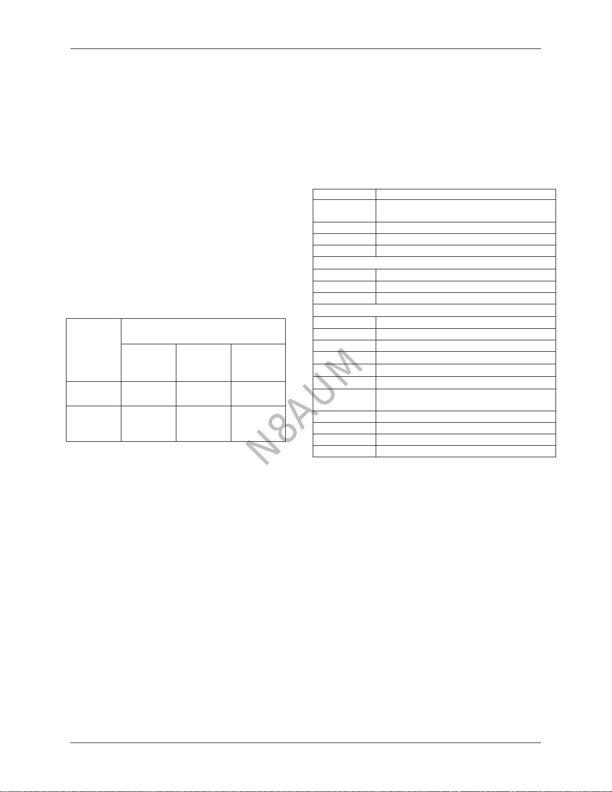
1-2.3 Range:
Usable: < 100 µV to 30 V rms.
Eight ranges selected by front panel switch:
100 µV to 1 mV FS
3 mV FS
10 mV FS
30 mV FS
100 mV FS
300 mV FS
1 V FS
3 V FS
(-70 dBm to -50 dBm)
(-40 dBm)
(-30 dBm)
(-20 dBm)
(-10 dBm)
(0 dBm)
(+10 dBm)
(+20 dBm)
-70 dB to +60 dB to 700 MHz with optional accessory
Model 1340A 100:1 divider.
dB readings are referenced to 0.221 V (0 dBm, 1 mW
into 50 ohms.)
N8AUM
Section 1. General Information
page 1-2
1-2.4 Crest Factor:
Range 1mV 3mV 10mV 30mV
Crest
Factor* 420 to 42 42 to 14 14 to 4.2 4.2 to 1.4
With 100:1 Divider
Range 0.1 V 0.3 V 1 V 3 V
Crest
Factor* 420 to 42 42 to 14 14 to 4.2 4.2 to 1.4
*Maximum permissible ratio of peak to rms value of
voltage
1-2.5 Accuracy (Frequency Effects):
The maximum uncertainty is the sum of frequency
effects and temperature effects.
Range Frequency
(FS) 10 kHz to
150 MHz 150 MHz
to 700
MHz
700 MHz
to 1.2
GHz
100 mV to
300 mV ±(1% FS +
1% Ind) ±(1% FS +
5% Ind) ±(1% FS +
12% Ind)
1 V to 3 V ±(1% FS +
1% Ind) ±(1% FS +
5% Ind) ±(1% FS +
12% Ind)
Note: FS = full scale; Ind= indication
*At 1 mV and below add ±1% FS
Ref. conditions: 20 to 25°C, 10 min warm-up
Measurements are referenced in 50 ohm systems using
the Ballantine 34402A probe with Model 5340A Tee
adapter and Ballantine 31-10189-1 precision 50 ohm
termination. Voltage is measured at the input
connector of the tee.
VSWR: 1.1 to 300 MHz, 1.2 to 1 GHz, and 1.3 to 1.2
GHz.
1-2.6 Temperature Effects (at 1 MHz):
A heater system in the detector probe maintains
detector temperature in the range of 23° to 28°C at all
ambient temperatures to 0°C.
Ambient With Probe
Heater Set To
25°C
With probe
heater set to
35°C
30°C to 40°C Add ±4% of
indication Add ±3% of
indication
25°C to 30°C Add ±1% of
indication Add +0.5% of
indication
10°C to 15°C Add ±1% of
indication Add ±1% of
indication
0°C to 10°C Add ±4% of
indication Add ±4% of
indication
1-2.7 Meter:
The instrument incorporates an analog meter for
readout. Three scales and antiparallax mirror are
provided. The 0 to 10 scale is uppermost and is 4.4
inches long. The 0 to 3 scale is below, followed by a -
10 to +3 dBm scale. dBm reference is .221 V equals 0
dBm (0 dBm = 1 mW into 50 ohms).
1-2.8 Indicator unrest: (1 mV FS range only)
Unrest of the meter pointer will be < ±1% FS above
uV indication, <±2% FS between 300 and 600 uV and
< ±5% FS from 100 µV to 300 µV.
1-2.9 Response Time and Overload Recovery:
Less than 1 second meter response on 3 mV to 3 V
ranges, increasing to 3 seconds rise time on 1 mV
range. The instrument recovers within 10% of final
indication within one minute after removing 3 V (rms)
overload on 1 mV range. A response switch permits
selection of slow or normal response times when
measuring input signals having time varying amplitude
components.
1-2.10 Detector Probe:
A detachable probe containing the RF detector is
provided. The shielded probe’s cable is 4 feet (1.2
meters) long and terminated in a quick disconnect
locking connector at the front panel. A Ground Clip
Lead is provided with the probe.
1-2.11 Probe Input Impedance:
Typical values measured at 21° to 25°C with probe
heater set to 25°C. Option 40 provides probe
(34403A) using diodes with equal capacitance and
higher input resistance limits.
1-2.12 Probe Input Shunt Capacitance at 100 kHz:
0 mV 2.8 pF
30 mV 2.7 pF
100 mV 2.5 pF
300 mV 2.3 pF
1 V 2.0 pF
3 V 1.8 pF
1-2.13 VSWR:
VSWR using probe with non-loading "T" connector in
a 50 ohm system is no greater than 1.3 from 10 kHz to
1.2 GHz.
1-2.14 Power Sensitivity:
Probe shall not require more than 1.8 nW of input
power at 300 µV input voltage when used with a non-
loading "T" connector in a 50 ohm system.
N8AUM
Section 1. General Information
page 1-3
1-2.15 Over Voltage:
Probe input is fully protected to 10 V ac on all ranges
and frequencies. Maximum dc input is ±400 V on all
ranges.
1-2.16 DC Recorder Output:
Rear panel banana jacks provide +1 V dc full scale
deflection on "10" ranges and .948 V on "3" ranges
into an open circuit. Source impedance is 1000 ohms
(±5%). DC output is short circuit proof. DC output
amplitude may be adjusted by a control accessible from
the rear panel. The dc recorder output voltage is
directly proportional to the meter deflection and the
rms of the probe input voltage. The DC Recorder
Output serves as an ac to dc converter.
1-2.17 Probe Balance:
A probe null balance (meter zero) control knob is
provided on the front panel. It permits meter zero
adjustment on the most sensitive ranges when no input
signal is present.
1-2.18 Relative References:
A REL REF control on the front panel allows
continuously variable reduction of sensitivity by a
minimum of 3.3 dB. It permits 0 dB reference level
change and is useful in setting the meter to
conveniently make readings when performing relative
dB measurements. A detented CAL position is
provided for normal measurements.
1-2.19 Meter Response Time:
1 second rise time on all ranges except 3 seconds on
the 1 mV range. A NORMAL/SLOW response switch
permits selection of meter response time for stable
measurements of input signals with varying
amplitudes.
1-2.20 Environmental Characteristics:
Temperature: Oper.: 0°C to +50°C, Stor. : -54°C to
+85°C
Humidity: (No condensation) 80% RH to 50°C, 95%
RH to 35°C
Altitude: Oper.: to 3 km (10,000 ft), Stor.: to 15 km
(50,000 ft)
Shock and Vibration: Complies with MIL-T-28800
Class 3, Style E.
EMI: Meets requirements of MIL-STD-461A for CS-
01, CS-06 and RS-03 to 400 MHz at 1 V/meter. There
is no discernible radiated or conducted RF leakage
from the instrument, the probe cable, or the probe.
1-2.21 Safety:
Meets conditions of MIL-T-28800, Class 3, Style E.
1-2.22 Power:
A fused power selector safety switch and receptacle on
the rear panel selects one of two ac operating voltage
ranges.
Hz,
108 to 132 V (115 V) 48 to 420 Hz
216 to 264 V (230 V) 48 to 420 Hz
Input Power: 10 VA maximum
With Option 05 - Internal rechargeable battery
Running Time: 8 hours
Rechargeable Time: 16 hours (20 hours maximum)
1-2.23 Dimensions:
Case Overall
Height 133 mm (5.25”) 147 mm (5.8”)
Width 211 mm (8.3”) 220 mm (8.66”)
Depth 280 mm (11”) 305mm (12”)
The case is all-aluminum with sturdy side extrusions,
front and rear die castings and quick disconnect top
and bottom covers. It includes a tilt bail and a side
mounted carry handle.
Weight: 3 kg (6.6 lbs) Net, 5.2 kg (11.5 lbs) Shipping
1-3. SPECIFICATIONS FOR OPTION 40
(USING PROBE 34403A)
1-3.1 Accuracy (Frequency Effects):
The maximum uncertainty is the sum of frequency
effects and temperature effects.
Range Frequency
(FS) 10 kHz to
100 MHz 100 MHz
to 1.0
GHz
1.0 GHz
to 1.2
GHz
100 mV to
300 mV ±(1% FS +
1% Ind) ±(1% FS +
3% Ind) ±(1% FS +
7% Ind)
1 V to 3 V ±(1% FS +
1% Ind) ±(1% FS +
3% Ind) ±(1% FS +
10% Ind)
Note: FS = full scale; Ind= indication
* At 1 mV and below add ±1% FS
Ref. conditions 20 to 25°C, 10 minutes warm-up
Measurements are referenced in 50 ohm systems using
the Ballantine 34403A probe with Model 5340A Tee
adapter and Ballantine 31-10189-1 precision 50 ohm
termination.
Voltage is measured at the input connector of the tee.
N8AUM
Section 1. General Information
page 1
-
4
Calibrated 10
Hz to 100 MHz; usable to >1.2 GHz.
The maximum uncertainty is the sum of frequency
effects and temperature effects.
Note:
FS = full scale; Ind = indication
* At 1 mV and below add ±1% FS
Ref
.
conditions 20 to 25°C, 10 minutes warm
-
up
Measurements are re
ferenced in 50 ohm systems using
the Ballantine 89
-
11657
-
1 probe with Model 5340A
Voltage is measured at the input connector of the tee.
Tee adapter and Ballantine 31
-
10189
-
1 precision 50
ohm termination.
Several o
ptions are available for the Model 3440A.
Desired options may be specified at time of purchase.
Contact your Ballantine representative for additional
i
nformation and availability
.
T
he
following
t
able
defines
the modifications,
option
a
nd accessories
.
.
3440A
-
STD
10KHz to 1.2 GHz m
i
l
livoltmeter
without
probe and accessories
3440A
3
440A
-
S
TD
with 4340A, 6340A, 34402A
3440A
-
M111
3440A with 34401A Kit
3440A
-
M113
3440A-M111,Substitute Probe 34403A
-
05
Rechargeable Internal Battery
-
40
Substitute Hi Precision Probe 34403A
-
41
Substitute Low Frequency Probe 34404A
1340A
100:1 Capacitive Divider for Probe
2340A
Non
-
Loading Probe Adapter for N & BNC
4340A
Probe Adapter, Spring
Tip w/Grd Clip
5340A
Tee
-
Adapter, Use w/50
Coax, Type N
6340A
50
Terminating Adapter, BNC & Type N
31
-
10189
-
1
50
Precision N Term. Use with 5340A
34401A
Kit: 1340A, 2340A, 5340A,31
-
10189
-
1 and 89
-
11103
-
1
34402A
Standard Probe, 10 kHz to 1.2 GHz
34403A
High Precision Probe, 10 kHz to 1.2 GHz
34404A
Low Frequency Probe, 10 Hz to 100 MHz
89
-
11103
-
1
Storage Case for Accessories
S
ee Fig. 1
-
1
a
and 1
-
1
b
f
or the accessories images.
100 mV to
300 mV
±(1% FS
+ 1% Ind)
±(1% FS
+ 3% Ind)
±(1% FS
+ 7% Ind)
1 V to 3 V
±(1% FS
+ 1% Ind)
±(1% FS
+ 3% Ind)
±(1% FS
+ 10%
Ind)
1
-
4.
ADDITIONAL SPECIFICA
TIONS FOR
THE OPTION 41 LOW FR
EQUENCY RF
PROBE (P/N
3
4404A
):
1
-
4.1
Frequency Range:
1
-
4.2
Accuracy (Frequency Effects):
1
-
5.
MODIFICATIONS,
OPTIONS
AND
ACCESSORIES.
Model
Description
Range
(FS)
Frequency
10 kHz to
150 MHz
150 MHz
to 700
MHz
700 MHz
to 1.2
GHz
Options
Accessories
Ω
Ω
Ω
N8AUM