MODEL
305A
For initial turn-on, or if instrumenr has been out of use for
2.4.2
-
Measurement
of
Peak-to
-
Peak
Value
of
many monrhs, permit a warmup period of at
le
asr 30 min-
Unsymmetrical
Waveforms
and
Pulse
Trains
-
ures. In ocher cases
10
minuees will suffice. Use the follow ing procedure:
PERMIT
AIR
TO
CIRCULATE
FREELY
AROUND
THE
IN-
SET
TO
STRUMENT.
The
volrmerer is
ca
librated
in
the
ve
rtical Function Swirch
PEAK·TO-
PEAK
position and
is
inrended for use
in
this manner. For con·
venienr reading a tilting device
is
provided beneath the case. Polarity Swirch POSITIVE,
if
Posirive Peak
is
High·
er
in
Amplirude, or
NEGATIVE,
if
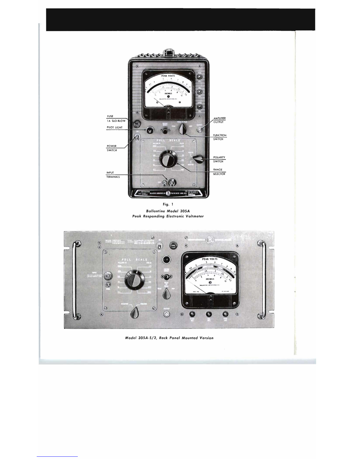
2.3 Function
of
Switches
Negarive Peak
is
Higher.
If
wave·
TITLE
POSITION
FUNCTION
form
is
not exacrly known,
use
peak
measuremenr
to
determine higher
Power
ON
Applies
AC
Power
ro
Insrrumenr peak.
If
polariry swirch
is
nor
in
OFF
Removes Power agreeme::m wirh higher pea.k, the
ac-
METER Depressed
Decreas~s
discharging time con- curacy of measurement may be af-
RESET stanr
of
derecror from
3.3
to
0.7
fected.
seconds for fast decay of poinrer. Other Controls
As
in
2.4.1
When
depressed, the reading
is
highly
in
error and no measure·
2.5
Measurement
of
Peak
Amplitudes
ment should be raken
in
rhis po·
sirion Before making a peak value measurement tile PEAK AOJ
control should be checked for calibrari on.
Tht
clleckinl! a
ncl
Function PEAK Disables Negative Peak DereCtor readjustment procedures arc outlined under
2.11.
3
,~
Switch Instrumenr indiGltes Peak Am·
plitude Chan
gi
ng rhe position of rhe po.lariry switch may cause a
PEAK-TO· Instrumenr measures Peak-to- switching rransient when making a peak measurement. This
PEAK Peak Amplitude of
Input
Wave·
effect
may
be eliminared
by
swirching rhe polarity switch
form ro posirive and rben negari
ve
shorrly before mc:tsuring.
AMP Connecrs Ourpur Amplifier
ro
The
procedure for measuring rhe peak value of a waveform
Outpur
Jack depends on its degree of symmer
ry.
Detector Circuit
is
disconnected 2.5.1 -
Nearly
Symmetrical
Waveforms
with
Polarity POSITIVE
The
ourput of the amplifier
is
in
Positive
and
Negative
Amplitudes
in Less
than
a
phase with the
vo
ltmeter input. 1
to
2 Ratio -Proceed
as
follows:
With
function
sw
itch in PEAK
position,
in
Strulllenr indicates
SET
TO
positive peak FunCtion Switcil PEAK
NEGATIVE
The
ourput
is
out
of phase with PoLlfiry
Sw
i
tcll
POSITIVE
ro
measure Positive
the volrmerer input.
With
func- Peak,
NEGA
TIVE to measure
rion swirch
in
PEAK posirion, Negarive Peak
instrument measures negarive
peak Orher Contro
ls
As
in
2
.4
.1
Range MILLIVOLTS Attenuates input signal and In·
Selecror
3.5
to
1000 clicat
es
full scale voltage. 2.
5.2
-
Unsymmetrical
Waveforms
with
Peak
VOLTS
Amplitudes
in
More
than
1
to
2 Ratio. Only rhe
3.5
to
1000 higher peak amplitude can be measured accurately.
Tile lower peak may be calculared
by
subtracting rhe
2.4
Measurement
of
Peak-to-Peak
Amplitudes
higher peak
amp
litude from rile peak-to-peak
va
l
ue
as
measured in
2.5
.
2.4.1 -
Measurement
of
Peak-to-Peak
Value
of
Symmetrical
Waveforms
(AC) -Measurement of
SET
TO
nearly symmerrical waveforms whose posirive and neg· FunCtion Swirch PEAK
ative amplitud
es
differ
by
less than a 1
to
2 ratio
is
accomplished
by
the following procedure: Polarity Switch Posirion giving Higher Indicarion
SET
TO
Orher Controls As
in
2.4.1
Function Swirch PEAK-TO-PEAK
Polarity Switch POSIT!
VE
2.6
AC
Overload
Considerations
Range
SeleCtOr
1000
vo
lr
s and
rum
coum
er-clock·
wise until rhe merer gives a sready
The
insrfllmt'nt
is
dcsigned
ro
wi
thsrnnd
se::vere
overloads
deAection wirhour damage
to
compOllents.
METER Depress
to
speed
clecay
of
pointer.
The
maxillluill AC
vo
lr
age which
Inay
be applied
ro
rhe
RESET Release and rake reading or wair for instrument on
rh
e four lowesr ranges
is
limited
by
rhe max-
indicaror decay imum
allo~·ed
\·olragc
ro
the grid of the first
rube::.
For an
- 4 -