Balluff Inductive Coupler
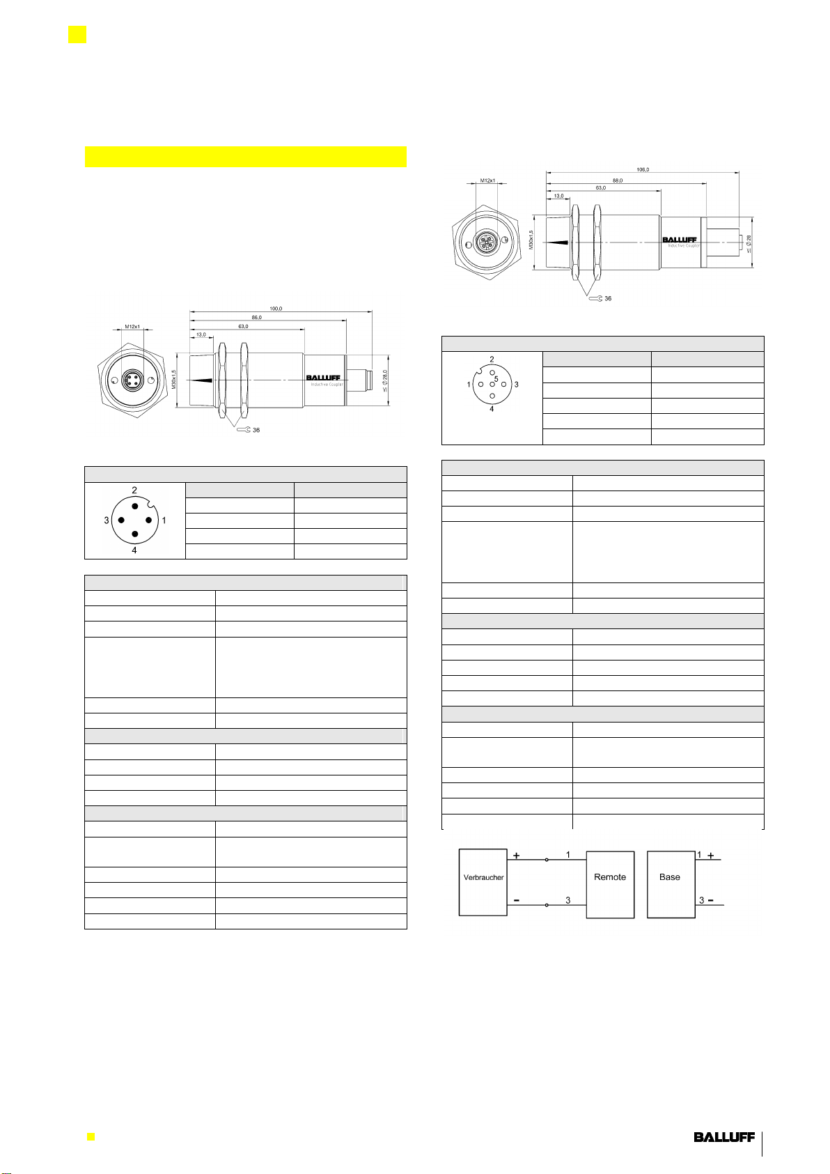
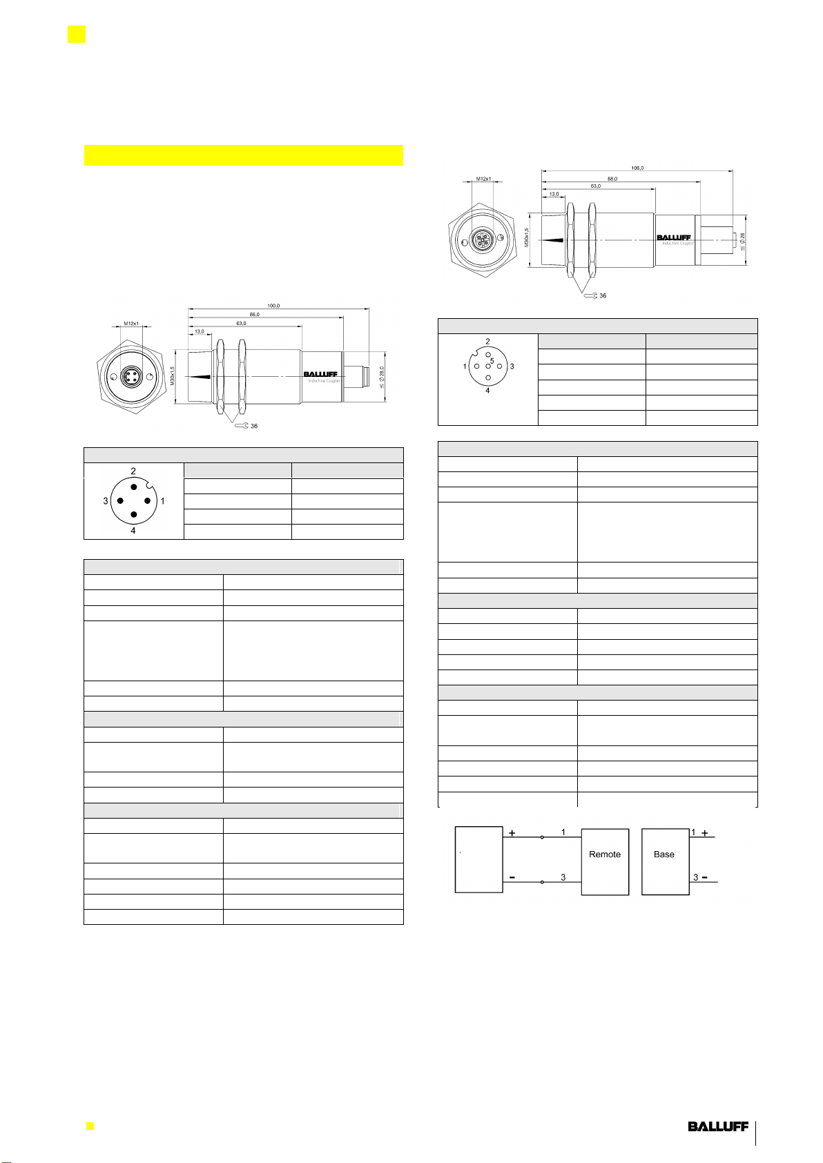
Base BIC 1P0-P2A50-M30MI3-SM4A4A und
Remote BIC 2P0-P2A50-M30MI3-SM4A5A
Sicherheitshinweise
Bestimmungsgemäße Verwendung
Das Gerät ist dazu konzipiert, eine Steckverbindung zu
ersetzen, um berührungslose Datenübertragung zu
gewährleisten.
Vor Inbetriebnahme ist die Betriebsanleitung
sorgfältig zu lesen!
Diese Sensoren dürfen nicht in Anwendungen
eingesetzt werden, in denen die Sicherheit
von Personen von der Gerätefunktion abhängt
(kein Sicherheitsbauteil gem. EU-
Maschinenrichtlinie).
Vorsicht!
Verbrennungsgefahr durch heiße
Oberflächen!
Die aktive Fläche erwärmt sich schon unter
normalen Einsatzbedingungen.
Hände und Gegenstände von der aktiven
Fläche fern halten.
Vermeiden Sie den Kontakt von metallischen
Gegenständen auf der aktiven Fläche.
Brandgefahr!
Zugelassenes Personal
Installation und Inbetriebnahme sind nur durch
geschultes Fachpersonal zulässig.
Sachwidrige Verwendung
Bei Schäden durch unbefugte Eingriffe oder nicht
bestimmungsgemäße Verwendung erlischt der Garantie-
und Haftungsanspruch gegenüber dem Hersteller.
Pflichten des Betreibers!
Das Gerät entspricht der EMV-Klasse A und kann
Funkenstörungen verursachen. Der Betreiber muss die
nötigen Vorkehrungen treffen.
Der Betreiber hat die örtlich geltenden Sicherheits-
vorschriften zu beachten.
Betriebsstörungen
Bei defekten und nicht behebbaren Störungen des
Geräts das Gerät außer Betrieb setzen und gegen
unbefugte Benutzung sichern.
Einbau
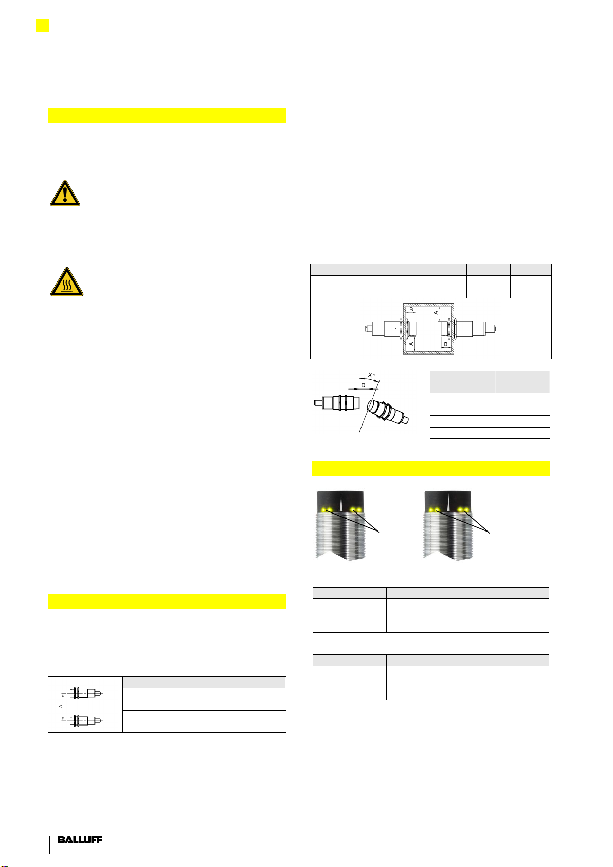
Gegenseitige Beeinflussung
Um eine gegenseitige Beeinflussung von nebeneinander
liegenden Bases oder Remotes zu vermeiden, müssen
die angegebenen Abstände eingehalten werden.
BIC 1P0-P2A50-M30MI3-
SM4A4A
BIC 2P0-P2A50-M30MI3-
SM4A5A
Einbau in Metall
Beim Einbau in Metall müssen unbedingt die
angegebenen Mindestabstände zu den umgebenden
Seiten des metallischen Objekts eingehalten werden,
weil sich sonst die Übertragungsentfernung zwischen
Sender und Empfänger verändert. Die Übertragungs-
Entfernung kann auch von der Metallart beeinflusst
werden.
Achtung!
Beschädigung des Geräts durch Induktionseffekte!
Metallische Objekte auf der Spulenkappe führen zur
Erhitzung der Objekte.
Die Komponenten so einbauen, dass sich keine
metallischen Objekte auf der Spulenkappe ansammeln
können.
BIC 1P0-P2A50-M30MI3-SM4A4A
BIC 2P0-P2A50-M30MI3-SM4A5A
Anzeigen
Base
Versorgungsspannung zu gering
Remote
Keine Verbindung zwischen Base und
Remote, keine Datenübertragung