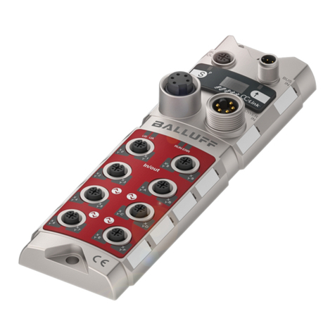
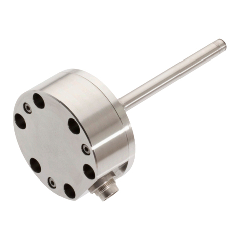
Balluff BIS L-409 Series User manual

Quick Guide
English
BIS L-409-045-00x-07-S4
A
41

www.balluff.com

www.balluff.com 3
5
4
3
2
1
BIS L-409 IO-Link Device
Processor
Notes to the user 5
1.1 About this manual 5
1.2 Structure of the manual 5
1.3 Typographical conventions 5
1.4 Symbols 5
1.5 Abbreviations 6
Safety 7
2.1 Intended use 7
2.2 General safety notes 7
2.3 Meaning of the warnings 7
Getting Started 8
3.1 Mechanical connection 8
3.2 Electrical connection 11
Basic knowledge 13
4.1 Function principle of Identification Systems 13
4.2 System topology 14
4.3 Read distance/offset 15
4.4 Product description 15
4.5 Data security 15
4.6 IO-Link basic knowledge 15
Technical Data 16
BIS L-409-045-001-07-S4 16
BIS L-409-045-002-07-S4 18
BIS L-409-045-003-07-S4 20
BIS L-409-045-004-07-S4 22
Appendix 24
Ordering code 24
Accessories 24

4
This manual describes processors in the series BIS L-409-... identification system as well as
startup instructions for immediate operation.
The manual is organized so that the sections build on one another.
Section 2: Basic safety information.
Section 3: The main steps for installing the identification system.
Section 4: Introduction to the material.
Section 5: Technical data for the processor.
Section 6: Mechanical and electrical connection.
Section 7: Basics for the IO-Link communications standard.
Section 8: User-defined processor settings.
Section 9: Integration into a fieldbus system using Profibus as an example.
Section 10: Processor and host system interaction.
The following conventions are used in this manual.
Enumerations are shown in list form with bullet points.
Entry 1,
Entry 2.
Action instructions are indicated by a preceding triangle. The result of an action is indicated by
an arrow.
Action instruction 1.
Action result.
Action instruction 2.
Numbers:
Decimal numbers are shown without additional indicators (e.g. 123),
Hexadecimal numbers are shown with the additional indicator hex (e.g. 00hex).
Parameters:
Parameters are shown in italics (e.g. CRC_16).
Directory paths:
References to paths in which data are stored or are to be saved to are shown in small caps (e.g.
Project:\Data tyPes\User DefineD).
Cross-references indicate where additional information on the topic can be found (see “Technical
data” starting page 16).
Attention!
This symbol indicates a security notice which most be observed.
Note, tip
This symbol indicates general notes.
–
–
►
⇒
►
–
–
1.1 About this
manual
1.2 Structure of the
manual
1.3 Typographical
conventions
Enumerations
Actions
Syntax
Cross-references
1.4 Symbols
Notes to the user
1
BIS L-409 IO-Link Device
Processor

www.balluff.com 5
BIS Balluff Identification System
CRC Cyclic Redundancy Code
DPP Direct Parameter Page
EMC Electromagnetic Compatibility
LSB Least Significant Bit
MSB Most Significant Bit
PC Personal Computer
SIO Standard IO
SPDU Service Protocol Data Unit
PLC Programmable Logic Controller
TCP Transmission Control Protocol
1.5 Abbreviations
Notes to the user
1
BIS L-409 IO-Link Device
Processor

6
BIS L-409-... processors together with the other components of the BIS L system comprise the
identification system.
They may be used only for this purpose in an industrial environment corresponding to Class A of
the EMC Law.
This description applies to the compact processors in the BIS L-409-... series.
Installation and startup
Installation and startup are to be performed only by trained specialists. Any damage resulting
from unauthorized manipulation or improper use voids the manufacturer's guarantee and war-
ranty.
When connecting the processor to an external controller, observe proper selection and polarity of
the connection as well as the power supply.
The processor must be powered only using approved power supplies (see “Technical data”
starting on page 16).
Attention!
This is a Class A device. This device may cause RF disturbances in residential areas;
in such a case the operator may be required to take appropriate countermeasures.
Operation and testing
The operator is responsible for observing local prevailing safety regulations.
When defects and non-clearable faults in the Identification System occur, take it out of service
and secure against unauthorized use.
Attention!
The pictogram used with the word “Caution” warns of a possible hazardous situation
affecting the health of persons or equipment damage. Ignoring these warnings can
result in injury or equipment damage.
Always observe the described measures for preventing this danger.►
2.1 Intended use
2.2 General safety
notes
2.3 Meaning of the
warnings
Safety
2
BIS L-409 IO-Link Device
Processor

www.balluff.com 7
3.1 Mechanical
connection
Getting Started
3
A
41
Fig. 1: BIS L-409-045-001-07-S4 with integrated read head, dimensions in mm
AClear zone
Attach the processor using 4 M4 screws.
Note maximum tightening torque of 15 Ncm.
In addition to the processor with integrated read head, the following processors with remote read
head are available.
The processors with remote read head are also tightened using 4 M4 screws to a max. tighten-
ing torque of 15 Ncm:
A
41
Fig. 2: Processor BIS L-409-045-002-07-S4, dimensions in mm
AClear zone
►
BIS L-409 IO-Link Device
Processor

8
A
41
Fig. 3: Processor BIS L-409-045-003-07-S4, dimensions in mm
AClear zone
A
A
41
Fig. 4: Processor BIS L-409-045-004-07-S4, dimensions in mm
AClear zone
Getting Started
3
BIS L-409 IO-Link Device
Processor

www.balluff.com 9
Data carrier Distance
BIS L-200-03/L > 25 cm
BIS L-100-05/L
BIS L-201-03/L > 30 cm
BIS L-101-05/L
BIS L-202-03/L > 40 cm
BIS L-102-05/L
Fig. 5: Distance between two processors, see table for legend
The following distances between individual BIS L-409_... systems must be maintained:
Processor Distance x Distance Y
BIS L-409-...-001- ... 1 m 1 m
BIS L-409-...-002- ... 0.5 m 0.3 m
BIS L-409-...-003- ... 0.5 m 0.3 m
BIS L-409-...-004- ... 0.5 m 0.3 m
Note
When installing two BIS L-409-... on metal there is normally no mutual interference.
Unfavorable use of a metal frame can result in problems when reading a data carrier.
In this case the read distance is reduced to 80% of the maximum value.
In critical applications a pre-test is recommended.
Distance
between data
carriers
Distance
between
processors
Getting Started
3
BIS L-409 IO-Link Device
Processor

10
7
8
Fig. 6: Overview of processor BIS L-409-045-001-07-S4
1Locking screw
2BIS L-409-045-001-07-S4
3IO-Link connection
4Ground connection
5LED 1
6LED 2
7Clear zone
8Read head
LED indicators on the processor:
Item LED Display Function
3 LED 1 green Supply voltage present
4 LED 2 yellow Tag Present
IO-Link port (M12, A-coded, female)
PIN Function
1 +24 V
2 NC
3 GND
4 C/Q
Connect data line to IO-Link Master.
(See Balluff IO-Link catalog for connection cable and accessories)
►
3.2 Electrical
connection
LED indicators
Data line
Getting Started
3
BIS L-409 IO-Link Device
Processor

www.balluff.com 11
ON
S101
ON
X1
S102
X3
X4
Fig. 7: Overview of BIS L-409-... processor
1X1 - Device terminal
2X3 - Read head terminal
3X4 - Jumper for operating mode
4S101/S102 - baud rate setting
The operating mode is set using jumpers in the processor (X4):
IO-Link mode, jumper setting as shown in Fig. 7 (factory default setting)
Service mode - to be used only by Balluff service
The baud rate is set using two DIP switches S101 and S102:
S102 S101 Baud rate
OFF OFF com1 4k8
OFF ON com1 4k8
ON OFF com2 38k4 *)
ON ON com3 230k4
*) Factory default setting
–
–
Operating mode/
baud rate
Getting Started
3
BIS L-409 IO-Link Device
Processor

12
4.1 Function
principle of
Identification
Systems
The BIS L-409-... Identification System is a non-contact read-only system. The compact proces-
sor consists of processing circuitry with a fixed read head.
The system may be used to read information which has been permanently programmed into the
data carrier and to send current status messages to the controller.
The main components of the BIS L-409-... Identification System are:
Processor,
read head,
data carriers.
Data transmission to the controlling system is accomplished using an IO-Link Master.
A
Fig. 8: Schematic representation of an identification system
The data carrier is an autonomous unit which is supplied with power by the read head. The read
head continuously sends a carrier signal which is picked up by the data carrier from within a
certain distance. As soon as the data carrier is powered up by the carrier signal, a static read
operation takes place.
The processor manages the data transfer between read head and data carrier, serves as a buffer
storage device, and sends the data to the host controller.
The data are passed to the IO-Link Master using IO-Link protocol, and the Master then passes
them to the controlling system.
Host systems may be the following:
A control computer (e.g. industrial PC),
a PLC.
The main areas of application are:
In production for controlling material flow (e.g. in model-specific processes), in workpiece
transport with conveying systems, for acquiring safety-relevant data.
warehousing for monitoring material movement,
transportation, and
conveying technology.
–
–
–
–
–
–
–
–
–
Basic knowledge
4
BIS L-409 IO-Link Device
Processor
Data carrier BIS L-2…
Connection to
IO-Link Master

www.balluff.com 13
Fig. 9: BIS L-409… topology
1PLC
2PC
3ProfiBus
4IO-Link Master
5Processors BIS L-409…
4.2 System topology
Basic knowledge
4
BIS L-409 IO-Link Device
Processor

14
Basic knowledge
4
4.3 Read distance/
offset
4.4 Product
description
4.5 Data security
4.6 IO-Link basic
knowledge
To ensure that data carriers are recognized without error and the data can be reliably read, do
not exceed a maximum distance and maximum offset between the data carriers and read heads
(see “Technical Data” starting page 16).
The “distance” specification refers to the maximum distance from the data carrier to the sensing
surface of the read head.
The “offset” specification indicates the maximum offset between the center axis of the data
carrier and the center axis of the sensing surface.
Data carriers can only be reliably recognized and the data reliably read within the permissible
read distance and offset. In the border area an unstable condition may occur, so that a data
carrier is alternately recognized and lost.
Data carrier recognition is indicated by an LED on the device (“TP – Tag Present”, see “Technical
Data” starting page 16). At the same time the CP bit is set in the input buffer (“CP – Codetag
Present”).
Processor BIS L-409-045-…-07-S4:
Plastic housing,
circular connector terminations,
one read head connected,
the read head suitable for dynamic or static operation,
data carrier is powered by the read head using a carrier signal.
In order to ensure data integrity, data transmission between the data carrier and processor can
be monitored using a check procedure.
In the processor a CRC_16 data check can be configured.
If the CRC check is enabled, the data carrier data are checked using a 2-byte CRC_16 check-
sum. If the checksum does not agree with the checked data, an error message is sent.
Note
The CRC_16 data check can only be used with data carriers of type BIS L-10X-05/L
The data carriers must be initialized using a BIS L-60_ _ processor and the
BISCOMRW.EXE PC software or a portable reader BIS L-81_ (refer to the User's
guide for the corresponding device for this procedure).
The manufacturer-specific standard IO-Link sends not only the actual process signal, but also all
relevant parameter and diagnostics data on the process level over a single standard cable.
Communication is based on a standard UART protocol with 24V pulse modulation; no separate
power supply is required. Connection is possible using a 2-conductor or 3-conductor cable.
Advantages of IO-Link:
Uniform, simple wiring of different devices
Controlling system can be used to change the device parameters
Remote querying of diagnostics information is possible
Centralized data retention of the device parameters is possible
–
–
–
–
–
–
–
–
–
BIS L-409 IO-Link Device
Processor

www.balluff.com 15
BIS L-409-045-
001-07-S4
Dimensions
Characteristic
data
Mechanical data
Technical Data
5
A
41
Fig. 10: Dimensions for BIS L-409-045-001-07-S4 processor [mm]
AClear zone
BIS L-409-045-001-07-S4
Characteristic data when used
with data carriers (installed in
clear zone)
When v = 0 (static)
Distance
[mm] read
Offset from center axis at distance: [mm]
0 - 20 0 - 35 0 - 45 0 - 15
BIS L-200-03 / BIS L-100-05 25 15 – – –
BIS L-201-03 / BIS L-101-05 35 – 20 – –
BIS L-202-03 / BIS L-102-05 48 – – 25 –
BIS L-203-03 / BIS L-103-05 16 – – – 10
Housing material Plastic (PBT)
Wiring Connector, M12 4-pin, A-coded
Enclosure rating IP65 (with connectors)
Weight 220 g
BIS L-409 IO-Link Device
Processor

16
Operating voltage VS 24 V DC +10/-20 %
Ripple ≤10 %
Current draw ≤150 mA
Load current capacity in SIO mode max. 50 mA
Output C/Q Short circuit protected
Device interface IO-Link
Ambient temperature range 0 °C … +70 °C
EMV
EN 301 489-1/-3
EN 61000-4-2/-3/-4/-5/-6
EN 300 330-1
–
–
–
Class A
Level 3A/3A/4A/2A/3A
Power class 5
–
–
–
Vibration/shock EN 60068 Part 2-6/27/29/64/32
Two LEDs on the communications module indicate the status:
LED indicator Function
LED green Supply voltage present
LED yellow Data carrier within read range (Tag Present)
Electrical data
Operating
conditions
Function
indicators
Technical data
5
BIS L-409 IO-Link Device
Processor

www.balluff.com 17
A
41
Fig. 11: Dimensions for BIS L-409-045-002-07-S4 processor [mm]
AClear zone
BIS L-409-045-002-07-S4
Characteristic data when used
with data carriers (installed in
clear zone)
When v = 0 (static)
Distance
[mm] read
Offset from center axis at distance: [mm]
0 - 10 0 - 15 0 - 20
BIS L-200-03 / BIS L-100-05 15 10 – –
BIS L-201-03 / BIS L-101-05 18 12 12 –
BIS L-203-03 / BIS L-103-05 10 4 – –
Housing material Plastic (PBT)
Read head housing material CuZn nickel plated
Wiring Connector, M12 4-pin, A-coded
Enclosure rating IP67
Weight 200 g
BIS L-409-045-
002-07-S4
Dimensions
Characteristic
data
Mechanical data
Technical data
5
BIS L-409 IO-Link Device
Processor

18
Operating voltage VS 24 V DC +10/-20 %
Ripple ≤10 %
Current draw ≤150 mA
Load current capacity in SIO mode max. 50 mA
Output C/Q Short circuit protected
Device interface IO-Link
Ambient temperature range 0 °C … +70 °C
EMV
EN 301 489-1/-3
EN 61000-4-2/-3/-4/-5/-6
EN 300 330-1
–
–
–
Class A
Level 3A/3A/4A/2A/3A
Power class 5
–
–
–
Vibration/shock EN 60068 Part 2-6/27/29/32/64
Two LEDs on the communications module indicate the status:
LED indicator Function
LED green Supply voltage present
LED yellow Data carrier within read range (Tag Present)
Electrical Data
Operating
conditions
Function
indicators
Technical data
5
BIS L-409 IO-Link Device
Processor

www.balluff.com 19
A
41
Fig. 12: Dimensions for BIS L-409-045-003-07-S4 processor [mm]
AClear zone
BIS L-409-045-003-07-S4
Characteristic data when
used with data carriers
(installed in clear zone)
When v = 0 (static)
Distance
[mm] read
Offset from center axis at distance: [mm]
0 - 5 0 - 8 0 - 11
BIS L-203-03 / BIS L-103-05 7 4 – –
Housing material Plastic (PBT)
Read head housing material*) CuZn nickel plated
Wiring Connector, M12 4-pin, A-coded
Enclosure rating IP67
Weight 170 g
BIS L-409-045-
003-07-S4
Dimensions
Characteristic
data
Mechanical data
Technical data
5
BIS L-409 IO-Link Device
Processor

20
Operating voltage VS 24 V DC +10/-20 %
Ripple ≤10 %
Current draw ≤150 mA
Load current capacity in SIO mode max. 50 mA
Output C/Q Short circuit protected
Device interface IO-Link
Ambient temperature range 0 °C … +70 °C
EMV
EN 301 489-1/-3
EN 61000-4-2/-3/-4/-5/-6
EN 300 330-1
–
–
–
Class A
Level 3A/3A/4A/2A/3A
Power class 5
–
–
–
Vibration/shock EN 60068 Part 2-6/27/29/32/64
Two LEDs on the communications module indicate the status:
LED indicator Function
LED green Supply voltage present
LED yellow Data carrier within read range (Tag Present)
Electrical Data
Operating
conditions
Function
indicators
Technical data
5
BIS L-409 IO-Link Device
Processor
This manual suits for next models
4
Table of contents
Other Balluff Industrial Electrical manuals
Popular Industrial Electrical manuals by other brands

Elvox
Elvox 692P/M Wiring instructions

Murata
Murata GRM216R71H222KA01 Series Reference sheet

Murata
Murata GRM0335C1H5R6CA01 Series Reference sheet

Murata
Murata GRM022R61A471MA01 Series Reference sheet

LEGRAND
LEGRAND Wattstopper DSW-100 installation instructions

Murata
Murata GJM0335C1E2R1WB01 Series Reference sheet

Murata
Murata GRM0335C1H7R3BA01 Series Reference sheet

National Instruments
National Instruments PXIe-4135 Getting started guide

FEAM
FEAM BMF Series Instructions for use

Murata
Murata GRM0225C1E5R5WA03 Series Reference sheet

Fagor
Fagor DRO Innova 40i P quick reference

Murata
Murata GRM32ER70J476KE20 Series Reference sheet