Balluff BAE PS-XA-1W-12-085-054 User manual

Diese Anleitung gilt für folgende Geräte:
BAE PS-XA-1W-12-085-54 (Bestellcode BAE00MC) Die gleiche Betriebsanleitung erhalten Sie auch im Internet unter
www.balluff.com.
Dieses Gerät ist ein primär getaktetes Schaltnetzgerät für die Ver-
wendung in Schalttafelinstallationen oder Einbauanwendungen, bei
denen der Zugang zum Netzgerät beschränkt ist (Berührungsschutz).
Das Gerät ist einsetzbar bei Verschmutzungsgrad 2.
Veränderungen am Gerät oder eine nicht bestimmungsgemäße
Verwendung sind nicht zulässig und führen zum Verlust von Gewähr-
leistungs- und Haftungsansprüchen gegenüber dem Hersteller.
Schaltnetzgeräte. BAE PS-XA-1W-12-085-054
Sicherheitshinweise
Gültigkeit Download der Betriebsanleitung
Bestimmungsgemäße Verwendung
Abmessungen
Installation
Installation
Vor Inbetriebnahme ist die Betriebsanleitung sorgfältig zu
lesen! Diese Geräte dürfen nicht in Anwendungen
eingesetzt werden, in denen die Sicherheit von Personen
von der Gerätefunktion abhängt (kein Sicherheitsbauteil
gem. EU-Maschinenrichtlinie).
Achtung!
Das Gerät gemäß den lokalen Vorschriften und Normen
ans Stromnetz anschließen. Das Gerät nicht abdecken!
Für die Kühlung ausreichend Raum um das Gerät
vorsehen, sonst kann sich das Gerät durch Überhitzung
abschalten. Die Lebensdauer des Geräts sinkt, sobald es
länger im überhitzten Zustand betrieben wird.
Das Gehäuse kann im Betrieb heiß werden!
Steckverbindungen nur bei ausgeschaltetem Strom
anschließen/trennen!
GEFAHR durch Hochspannung!
Die Berührung ungeschützter Leiter und Komponenten
kann zum Tod durch Stromschlag oder zu schweren
Verbrennungen führen.
Vor Arbeiten am Gerät die Stromversorgung unterbre-
chen und gegen Wiedereinschalten sichern. Keine
Gegenstände in das Gerät einführen. Von Feuer und
Wasser fernhalten.
GEFAHR durch elektrische Lichtbögen und tödlichen
Stromschlag!
Solange das Gerät in Betrieb ist, die Installation nicht
ändern! Dasselbe gilt für die Sekundärseite.
Die Installation und die Inbetriebnahme sind nur durch geschultes
Fachpersonal zulässig.
Der Betreiber hat die Verantwortung, dass die örtlich geltenden
Sicherheitsvorschriften eingehalten werden.
Insbesondere muss der Betreiber Maßnahmen ergreifen, dass bei
einem Defekt des Geräts keine Gefahren für Personen und Sachen
entstehen können.
Bei Defekten und nicht behebbaren Störungen des
Schaltnetzgeräts ist dieses außer Betrieb zu nehmen und gegen
unbefugte Benutzung zu sichern.
158
97
Ø3.5
Ø3.5
38
Bild 1: Abmessungen
Bild 2: Schaltnetzgerät befestigen. Position A
Montage
Für ausreichende Lüftung und Kühlung wird ein Raum von 25 mm
auf allen Seiten des Geräts empfohlen. Die Lüftungslöcher freihalten.
Falls mehrere Schaltnetzgeräte nebeneinander montiert werden,
genügend Abstand zwischen den Geräten einhalten, damit die
Lüftung gewährleistet wird.
1. Das Gerät gem. Bild 2 und 3 mit M3 Schrauben befestigen.
Beachten Sie: Die Schrauben dürfen eine Maximallänge nicht
überschreiten (4 mm bei Position A, 5 mm bei Position B).
Längere Schrauben können einen Kurzschluss verursachen.
2. Um Störungen zu vermeiden, die Eingangs- und die Ausgangs-
stromkabel getrennt voneinander verlegen.
Ausbau
1. Stromversorgung ausschalten und System vom Versorgungsnetz
trennen. Alle Steckverbinder vom Netzgerät trennen.
2. Die Schrauben lösen und das Gerät vorsichtig entfernen.
Montageposition A
Installation (Fortsetzung)
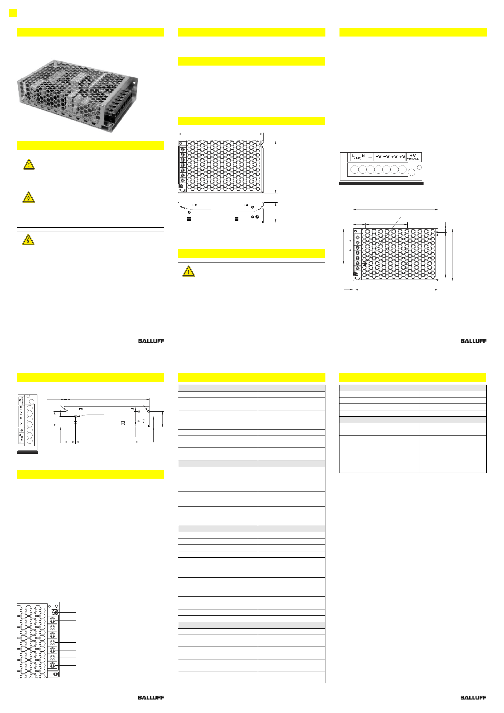
Anschlüsse
Technische Daten Technische Daten
Montageposition B
Bild 3: Schaltnetzgerät befestigen. Position B
Interne Sicherung
Die interne Eingangssicherung dient dem Schutz des Geräts und darf
vom Benutzer nicht ausgetauscht werden. Bei einem internen Fehler
ist das Gerät aus Sicherheitsgründen an den Hersteller zurückzuschi-
cken.
Elektrische Anschlüsse
−Daten für zulässige Lasten siehe Tabelle ”Technische Daten”.
−Ausschließlich kommerzielle Kabel verwenden, die für die
angegebenen Spannungs- und Stromwerte geeignet sind.
−Bei Flexkabeln sicherstellen, dass alle Litzen in der Klemme
gesichert sind (mögliche Gefahr eines Kurzschlusses).
−Korrekte Polarität am Ausgang sicherstellen.
−Bei Bedarf muss ein manuell steuerbares Trennelement zur
Trennung vom Versorgungsnetz verwendet werden.
−Geräte- und Stromkabel müssen korrekt abgesichert sein.
Erdung
Nicht ohne GND-Anschluss betreiben!
−Der ungesicherte Erdungsleiter muss an GND (Schutzklasse 1)
angeschlossen sein.
−Die Sekundärseite ist nicht geerdet. Bei Bedarf kann die Plus-
oder Minus-Klemme optional geerdet werden.
+
+
–
–
PE
N
L
V ADJ
OUT
Max. Anzugsdrehmoment für
Steckverbindung: 1,2 Nm
Bild 4: Anschlüsse
Elektrische Daten
Isolationsspannung
3000 V AC/ 4242 V DC
Isolationswiderstand
>100 MΩ
Einschaltzeit
< 1500 ms
Einschaltzeit mit kapazitiver Last
< 2000 ms 7000 µF µF
Einschwingzeit
< 150 ms
Einschwingzeit mit kapazitiver Last
< 500 ms 7000 µF
Schaltfrequenz f
100 kHz (typ)
Schaltmodus parallel
Schaltmodus in Reihe
nicht möglich
max. 2 Geräte
Temperaturkoeffizient
±0,03% / °C
Wirkungsgrad Typ / Avg
87% / 87%
Eingangsdaten
Eingangsspannung
100...240 V AC
Eingangsspannungsbereich
88 V AC...264 V AC
120 V DC...375 V DC
Eingangsnennstrom
max. 1500 mA
Einschaltstrom
115 V AC
230 V AC
< 35 A
< 60 A
Frequenzbereich
47...63 Hz
Eingangssicherung
T3.15 A / 250 V AC, intern
Power Factor Correction (PFC)
gem. EN61000-3-2 Klasse D
Ausgangsdaten
Ausgangsnennspannung
12 V DC
Initial voltage setting
12 V + 1%
Ausgangsnennstrom
8,5 A
Ausgangsleistung
102 W
Einstellbereich Ausgangsspannung
@0.8 lo
10,8...13,2 V DC
Derating
3% / °C von 46 °C bis +71 °C
Restwelligkeit @ lo nom
100 mV p-p
Spannungsregelung
±0,5%
Lastregelung
±1.0%
Überlastsicherung
130%...160%
Überlastschutz @0.8 lo
13,8...16,2 V DC
Kurzschlussverhalten
Hiccup Modus
Netzausfallüberbrückung (230 V AC)
> 70 ms
Abfallzeit
< 150 ms
Mechanische Daten
Werkstoff Gehäuse
Metall
max. Freiraum
25 mm auf allen Seiten des
Geräts
Gewicht
530 g
Abmessungen L x B x H mm
158 x 97 x 38
Anschluss
AWG 22...14
2
0,2...2 mm
Befestigung
M3-Schrauben, max. Länge
4 mm bzw. 5 mm
Umgebungsbedingungen
Betriebstemperatur
–40...+71 °C
Lagertemperatur
–40...+85 °C
relative Luftfeuchtigkeit
20%...95% RH
Kühlung
Luftselbstkühlung
Zulassungen und Normen
UL / cUL
UL 60950-1 Recognized
TÜV
EN 60950-1
CE
EN 61000-6-3, EN 61000-3-2,
EN 61000-3-3,EN 61000-6-2,
EN 61000-4-2, EN 61000-4-3,
EN 61000-4-4, EN 61000-4-5,
EN 61000-4-6, EN 61000-4-8,
EN 61000-4-11, EN 61204-3,
EN 55022 Class B
Balluff GmbH
Schurwaldstraße 9
73765 Neuhausen a.d.F.
Deutschland
Tel. +49 7158 173-0
Fax +49 7158 5010
balluff@balluff.de
Dok.-Nr./Doc. no. 916 459 DE/EN . I14; Änderungen vorbehalten/Subject to modification
5.50
117
23
3 x M3
L = max. 5 mm
150
19.30 28.80
28.50
10.80
18
Ø3.5
Ø3.5
23
5153
2 x M3
L = max. 4 mm
78
158
9.5065
97
84.50 7

This guide is valid for the following devices:
BAE PS-XA-1W-12-085-54 (ordering code BAE00MC) The user's guide can also be found on the Internet at
www.balluff.com.
This device is a primary switched-mode power supply for integration
in control panel installations or integral applications where access to
the power supply is restricted (contact protection).
The device is suitable for pollution severity level 2.
Modifications to the device or non-approved use are not permitted
and will result in loss of warranty and void any liability claims against
the manufacturer.
Switched-mode power supplies. BAE PS-XA-1W-12-085-054
Safety notes
Validity Downloading the user's guide
Proper use
Dimensions
Installation
Installation
Before commissioning, read the user's guide carefully!
These devices must not be used in applications in which
the safety of persons is dependent on the function of the
device (not a safety component acc. to EU Machinery
Directive).
Important!
Connect the device to power supply in accordance with
local regulations and standards. Do not cover the device!
Provide enough space around the device for cooling.
Otherwise, the device may switch off due to overheating.
Operating the device in an overheated state for a
prolonged period shortens the service life of the device.
The housing may become hot during operation!
Always switch the power off before connecting /
disconnecting plug connections!
DANGER due to high voltages!
Contact with unprotected conductors and components
can result in fatal electric shock or severe burns.
Before starting work on the device, disconnect the power
supply and secure it to prevent it from being restarted.
Do not insert foreign objects into the device. Keep away
from fire and water.
DANGER due to electric arcing and deadly electric
shocks!
Do not modify the installation while the device is
operating! This also applies to the secondary side.
Installation and startup are to be performed by trained technical
personnel only.
The operator is responsible for ensuring that local safety regulations
are observed.
In particular, the operator must take measures to ensure that a defect
in the device will not result in hazards to persons or equipment.
If defects and persistent faults occur in the switched-mode power
supply, take it out of service and secure it to prevent any unautho-
rized use.
158
97
Ø3.5
Ø3.5
38
Fig. 1: Dimensions
Fig. 2: Fastening the switched-mode power supply. Position A
Installation
FWe recommend leaving a gap of 25 mm around the device to allow
for adequate ventilation and cooling. Do not obstruct the ventilation
holes.If multiple switched-mode power supplies are installed next to
each other, provide enough distance between the devices to ensure
adequate ventilation.
1. Secure the device with M3 screws in accordance with Figure 2
and 3. Please note: the screws may not exceed the maximum
length (4 mm for Position A, 5 mm for Position B). Longer screws
can cause a short-circuit.
2. Lay the input and output power cables separately from each other
to prevent interference.
Removal
1. Switch off the power supply and disconnect the system from the
power grid. Disconnect all connectors from the power supply.
2. Loosen the screws and carefully remove the device.
Installation position A
Installation (continued)
Connections
Technical data Technical data
Installation position B
Fig. 3: Fastening the switched-mode power supply. Position B
Internal fuse
The internal input fuse protects the device and must not be replaced
by the user. If an internal fault occurs, return the device to the
manufacturer as a precautionary measure.
Electrical connections.
Electrical connections
−For data on permissible loads, see the "Technical data" table.
−Only use commercial cables suitable for the specified current and
voltage values.
−For flexible cables, make sure that all strands are secured in the
terminal (possible risk of a short-circuit).
−Make sure the polarity at the output is correct.
−If necessary, a manually controlled separating element for
isolating the power supply must be used.
−Device and power cables must be properly protected by a fuse.
Grounding
Do not operate without a GND connection!
−The unsecured ground conductor must be connected to GND
(insulation class 1).
−The secondary side is not grounded. If necessary, the plus or
minus terminal can be grounded
+
+
–
–
PE
N
L
V ADJ
OUT
Max. tightening torque for
plug connector: 1,2 Nm
Fig. 4: Connections
Balluff GmbH
Schurwaldstraße 9
73765 Neuhausen a.d.F.
Germany
Tel. +49 7158 173-0
Fax +49 7158 5010
balluff@balluff.de
Dok.-Nr./Doc. no. DE/EN . I14; Änderungen vorbehalten/Subject to modification916 459
Ambient conditions
Operating temperature
–40...+71 °C
Storage temperature
–40...+85 °C
Relative humidity
20%...95% RH
Cooling
Free air convection
Approvals and standards
UL / cUL
UL 60950-1 Recognized
TÜV
EN 60950-1
CE
EN 61000-6-3, EN 61000-3-2,
EN 61000-3-3,EN 61000-6-2,
EN 61000-4-2, EN 61000-4-3,
EN 61000-4-4, EN 61000-4-5,
EN 61000-4-6, EN 61000-4-8,
EN 61000-4-11, EN 61204-3,
EN 55022 Class B
Electrical data
Isolation voltage
3000 V AC/ 4242 V DC
Isolation resistance
>100 MΩ
Turn-on time
< 1500 ms
Turn-on time with capacitive load
< 2000 ms 7000 µF
Rise time
< 150 ms
Rise time with capacitive load
< 500 ms 7000 µF
Switching frequency f
100 kHz (typ)
Parallel mode
In line
Not possible
Max. 2 devices
Temperature coefficient
±0.03% / °C
Efficiency (Typ) / (Avg)
87% / 87%
Input data
Input voltage
100...240 V AC
Input voltage range
88 V AC...264 V AC
120 V DC...375 V DC
Rated input current
max. 1500 mA
Inrush current
115 V AC
230 V AC
< 35 A
< 60 A
Frequency
47...63 Hz
Input fuse
T3.15 A / 250 V AC, intern
Power Factor Correction (PFC)
meet EN61000-3-2 Class D
Output data
Nominal output voltage
12 V DC
Initial voltage setting
12 V + 1%
Nominal output current
8.5 A
Output wattage
102 W
Voltage trim range @0.8 lo
10.8...13.2 V DC
Derating
3% / °C from 56 °C to +71 °C
Ripple @ lo nom
100 mV p-p
Line regulation
±0.5%
Load regulation
±1.0%
Rated overload protection
130%...160%
Over voltage protection @0.8 lo
13.8...16.2 V DC
Output short-circuit
Hiccup mode
Hold-up time (230 V AC)
> 70 ms
Dropout time
< 150 ms
Mechanical data
Housing material
Metal
Max. required free space
25 mm on all sides of the
device
Weight
530 g
Dimensions (L x W x H) mm
158 x 97 x 38
Connection
AWG 22...14
2
0,2...2 mm
Fastening
M3 screws, max. length
4 or 5 mm
5.50
117
23
3 x M3
L = max. 5 mm
150
19.30 28.80
28.50
10.80
18
Ø3.5
Ø3.5
23
5153
2 x M3
L = max. 4 mm
78
158
9.5065
97
84.50 7
Table of contents
Languages:
Other Balluff Power Supply manuals
Popular Power Supply manuals by other brands

STAMOS
STAMOS S-LS-88 user manual

Puls
Puls MiniLine ML30 instruction manual

Universal Voltronics
Universal Voltronics BRC-15-1111R-STD-J37 instruction manual

Festo
Festo SVG-1/230VAC-48VDC-10A Installation notes for electrical personnel

Omron
Omron S8VK-G Series instruction manual

HIOS
HIOS CLT-100 Operation manuals