IDEC PS3X Series User manual

ӕৢᛟଢ
ೞ֥ኵᡂLjဇǹǤȃȁȳǰȑȯȸǵȗȩǤ
Ჭ᳒ǷȪȸǺ
$
ƜƷࡇƸŴ+&'%ᙌԼǛƓᝰƍɥƛƍƨƩƖŴƋǓƕƱƏƝƟƍLJƢŵƝද૨ƷᙌԼƴ᧓ᢌƍƕƳƍƔƝᄩᛐƷƏƑŴƜƷӕ
ৢᛟଢƷϋܾǛǑƘƓᛠLjƍƨƩƖŴദƠƘƝဇƘƩƞƍŵLJƨŴƜƷӕৢᛟଢƸȦȸǶಮƴƯٻЏƴሥɦƞƍŵ
ܤμɥƷƝද
ŪஜӕৢᛟଢưƸŴᛚƬƨӕǓৢƍǛƠƨئӳƴဃơǔƜƱƕʖยƞǕǔүᨖƷࡇӳƍǛžᜩԓſžදſƱƠƯғКƠ
ƯƍLJƢŵƦǕƧǕƷԛƸˌɦƷᡫǓưƢŵƜǕǒƷᜩԓȷදʙƸ࣏ƣܣƬƯƘƩƞƍŵ
ŪஜᙌԼƸСࣂႴǍᙌԼϋᢿƴኵᡂǜưဇƢǔᩓเưƢŵٳ˄ƚưဇƠƳƍưƘƩƞƍŵ
ӕৢƍǛᛚƬƨئӳŴʴƕരʧLJƨƸͻǛƏӧᏡࣱƕƋǓLJƢŵ
Ūᛚદ˺ǍʙƕႺʴ˳ǍဃԡǛᏣƔƢǕƷƋǔೞ֥Ҕၲೞ֥ŴᑋᆰೞŴᑋᆰܢܬೞŴЗŴҾ܇щሁƴƸဇƠƳ
ƍưƘƩƞƍŵஜᩓเƸŴСࣂႴǍɟᑍᩓ܇ೞ֥ᡫೞ֥Ŵᚘยೞ֥Ŵငಅဇᩓ܇ೞ֥ሁƴኵᡂǜưဇƞǕǔǑƏƴ
ᙌ˺ƞǕƯƍLJƢŵ
ŪဇவˑƕᩓเƷǫǿȭǰƴᚡ᠍ƷϋܾƱႻᢌƷƳƍƜƱǛ࣏ƣƝᄩᛐƘƩƞƍŵஇኳೞ֥ƷᚨᚘǍᩓเƷዓӏƼᡫᩓ
ƷЭƴŴˁಮƷϋܾǛᄩᛐƠƯƘƩƞƍŵϋܾƴɧଢƳໜƕƋǔئӳƸŴᡫᩓƢǔЭƴࡴᅈLJưƝႻᛩƘƩƞƍŵ
ŪƓܲಮưƷྸǍોᡯƸዌݣƴƓǍNJɦƞƍŵྸǍોᡯƸᩓ້໎ᄊْᛚ˺ѣሁŴٻƳʙƴƭƳƕǓLJƢŵ
ŪᡫᩓɶƴႺʴ˳ƕᚑǕǔǑƏƳӕ˄ƚŴӏƼ˺ಅƸƠƳƍưƘƩƞƍŵᡫᩓɶӏƼഥႺࢸƸŴ᭗ภȷ᭗ᩓןƴƳƬƯ
ƍǔᢿЎƕƋǓ້ͻǍᩓƷүᨖƕƋǓLJƢƷưᚑǕƳƍưƘƩƞƍŵ
ŪЈщᇢ܇᧓ŴLJƨƸЈщȪȸȉዴǛǷȧȸȈƞƤƳƍưƘƩƞƍŵ້໎ȷᨦሁƷҾ׆ƱƳǓLJƢŵ
ŪᩓเᨦƷᒵƷᛚ˺ѣǍᄊْሁǛܭƠƨᜱݣሊǛஇኳೞ֥ƴኵᡂǜưƘƩƞƍŵᩓเᨦƸŴЈщᇢ܇ƴᢅٻ
ƳᩓןƕႆဃƠƨǓŴᩓן˯ɦƱƳǔئӳƕƋǓLJƢŵ
ŪᣐዴƢǔƱƖƸŴᩓเǛЏƬƯƔǒ˺ಅǛᘍƬƯƘƩƞƍŵᣐዴ᧓ᢌƍƷƳƍǑƏҗЎƴදǛƠƯƘƩƞƍŵᩓȷ
ᨦƷҾ׆ƱƳǓLJƢŵ
ӕৢƍǛᛚƬƨئӳŴʴƕͻǛƏƔཋႎܹƕႆဃƢǔӧᏡࣱƕƋǓLJƢŵ
ŪൿNJǒǕƨλщᩓןǛ࣏ƣܣƬƯƘƩƞƍŵ#%ȩǤȳƷȒȥȸǺƕЏǕƨǓŴႆȷႆ້ƷҾ׆ƴƳǓLJƢƷưŴ
λщᇢ܇ȷЈщᇢ܇ƷಊࣱƓǑƼᛚዓƷƳƍƜƱǛᄩᛐƠƯƔǒᡫᩓƠƯƘƩƞƍŵ
ŪᩓเƷӕ˄ƚƸŴஜ˳ƕᄩܱƴܭƞǕƯƍǔƔƝᄩᛐƘƩƞƍŵ
ŪᩓเϋᢿƴᚑǕƳƍưƘƩƞƍŵLJƨŴီཋƕλǓᡂLJƳƍǑƏƴƠƯƘƩƞƍŵᩓเƷϋᢿᢿԼƴᚑǕƨǓŴǯȪ
ȃȗŴƶơሁƷီཋƕλǓᡂljƱŴʙǍᨦƷҾ׆ƱƳǓLJƢŵ
ŪภࡇȇǣȬȸȆǣȳǰǛ࣏ƣܣƬƯƘƩƞƍŵဇԗภࡇƸŴᩓเ್ƷภࡇưƢŵภࡇȇǣȬȸȆǣȳǰǛᄩᛐƠ
ƯƘƩƞƍŵϋᢿภࡇƕɥଞƠŴᨦƷҾ׆ƱƳǓLJƢŵ
ŪᲾᲽλщưƝဇƷئӳƸŴ࣏ƣٳᢿƴᲾᲽλщဇȒȥȸǺǛዓƠƯƝဇƘƩƞƍŵ
ŪЈщᩓןᛦૢဇȜȪȥȸȠƸܭЈщᩓןƷdˌɥƴׅƞƳƍưƘƩƞƍŵᩓเƷࣱᏡэ҄ǍᨦƷҾ׆ƴƳ
ǓLJƢŵ
ŪဇɶƴᨦLJƨƸီࠝƕႆဃƠƨƱƖƸŴƢƙƴλщǛᢚૺƠƯᩓเǛഥƞƤƯƘƩƞƍŵLJƨŴƜƷئӳႺƪ
ƴࡴᅈLJƨƸˊྸࡃƴƝႻᛩƘƩƞƍŵ
ŪѣȷᘔએƷٶƍئưƷƝဇǍŴሥƸƠƳƍưƘƩƞƍŵᨦƷҾ׆ƴƳǓLJƢŵ
ŪഏƷئưƷᚨፗŴƝဇƸƞƚƯƘƩƞƍŵ
ĬႺݧଐήƷ࢘ƨǔئŴଡ଼ೞ֥ሁƷᡈƘŴӏƼ᭗ภƴƳǔئŵ
ĭᤧብŴŴᕤԼŴᄑ҄൦እሁƷƔƔǔǕƷƋǔئŵ
ĮעɦܴŴภܴሁƷࡇƷ᭗ƍئŵ
įϬϵࡉϋŴǯȸȩȸƷԉƖЈƠӝƷദ᩿ሁŴภࡇƷ˯ƍئŵ
ද
ᜩԓ
3ܭ
2ؾ
1ᢘဇᙹ
ܤμᙹᲴ7.%5#%0Q'0+'%
Ჿ᳇ᲽᲴ'0%.#55$
'025:$šƷLj
'0'0
ѣ˺ԗภࡇᲴ᳸é25:$š%š൧ኽƠƳƍƜƱŴЈщȇǣȬȸȆǣȳǰӋༀ
᳸é25:&š3š'š൧ኽƠƳƍƜƱŴЈщȇǣȬȸȆǣȳǰӋༀ
܍ภࡇ Ჴ᳸é൧ኽƠƳƍƜƱ
ѣ˺ႻݣࡇᲴ᳸4*ኽᩧƠƳƍƜƱ
܍ႻݣࡇᲴ᳸4*ኽᩧƠƳƍƜƱ
൲௨ࡇ Ჴ
=ᘙ?ƴᚡ᠍ƷርЈщᩓןgЈщᩓ්ġЈщᩓщưƝဇƘƩƞƍŵ
ܤμᙹưƷ১ᛐภࡇǛɦᚡƴᅆƠLJƢŵ
ǿǤȗ
25:$š%š
১ᛐภࡇé
INSTRUCTION SHEET
Switching Power Supply
PS3X Series
Confirm that the delivered product is what you have ordered. Read this instruction sheet to make sure of
correct operation. Make sure that the instruction sheet is kept by the end user.
SAFETY NOTE
࣭In this operation instruction sheet, safety precautions are categorized in order of importance to Warning and
Caution : The PS3X switching power supplies are designed for installation in a Industrial control panel. This product
cannot be used outside of equipment. Embed this product inside an appropriate enclosure before using the product.
Warning no ices are used to emphasize that improper operation may cause severe personal injury or death.
࣭Do not use the switching power supply on control equipment in medical equipment, aircraft, aerospace craft, trains, and
atomic equipment where malfunction of the switching power supply may cause severe personal injury or threaten human
life. These switching power supplies are designed for use on general electronic equipment such as communication
equipment, instrumentation equipment, and industrial control equipment.
࣭Make sure that the operating conditions sa isfy the values described in the catalog. Confirm the specification values
before designing the equipment to use the switching power supply and before supplying power. Contact IDEC if you
have any question.
࣭Do not modify or repair the switching power supply. Modifica ion or repairing of the switching power supply by users may
cause electrical shocks, damage, fire, malfunction, and other heavy accidents.
࣭Do not install the switching power supply where a human body may come into contact while power is supplied to the
switching power supply. Do not touch the switching power supply during operation or immediately after turning off
because some parts are heated and at a high voltage, causing burns or electrical shocks.
࣭Do not connect the output terminals or output lead wires together. Fire or damage may result.
࣭Include a protection in the equipment using the switching power supply in considera ion of malfunction or damage of the
load in case the switching power supply should fail. If the switching power supply should fail, a very high voltage drop
may occur at the output terminals.
࣭Turn power off before wiring the switching power supply. Make sure of correct wiring. Incorrect wiring may cause
electrical shocks or damage.
Caution notices are used where inattention might cause personal injury or damage to equipment.
࣭Make sure of the correct input voltage. Incorrect input voltage may cause blown fuses, fuming, or fire. Make sure of
correct polarity of input and output terminals before supplying power to the switching power supply.
࣭Mounting the switching power supply, make sure that the body has been securely fixed.
࣭Do not touch any part inside the switching power supply. Prevent foreign objects from entering into the housing of the
switching power supply. If the internal parts are touched by hand or foreign objects such as a paper clip or screw
entering into the housing, accidents or damage may occur.
࣭Observe the temperature derating. The operating temperature is the temperature around he switching power supply.
Use he switching power supply within the temperature derating curve. Otherwise, the internal temperature will rise and
damage may be caused.
࣭For DC input, make sure to install an external fuse.
࣭Do not turn the output voltage adjustment beyond the limits. Otherwise, the switching power supply may be deteriorated
and damage may be caused.
࣭When damage or malfunction should occur during operation, immediately turn power off and stop the switching power
supply. Contact IDEC.
࣭Do not use or store the switching power supply in environments subjected to a large amount of vibrations or shocks.
Otherwise, damage may be caused.
࣭Do not install the switching power supply in environments exposed to direct sunlight, iron particles, oil splashes,
chemicals, and hydrogen sulfide. Do not use the switching power supply in humid places such as basements or
greenhouses or in low-temperature places such as in freezers or in front of cooler outlet.
1Safety Standard Conditions
Applicable standards: UL60950-1, CSA C22.2 No.60950-1, EN60950-1, IEC60950-1
2Conditions
3Rating
Operating temperature : -20 to +70
o
C (PS3X-Bڧ, -Cڧ) (without freezing, see output derating)
-10 to +70
o
C (PS3X-Dڧ, -Qڧ, -Eڧ) (without freezing, see output derating)
Storage temperature : -40 to +85
o
C (without freezing)
Operating humidity : 20 to 85% RH (without condensation)
Storage humidity : 10 to 95% RH (without condensation)
Pollution degree : 2
EMC: EN55032 CLASS B
EN61000-3-2,-3(PS3X-Bڧonly)
EN55024, EN61000-4-2, -3, -4, -5, -6, -8, -11
Note: In order to comply with safety standards,the ambient operating temperature is as below.
Type
PS3X-Bڧ, -Cڧ50
25:&š3š'š
PS3X-Dڧ, -Qڧ, -Eš
45
Temperature(
o
C)
Use the switching power supply with he output wattage within the values shown in the [Table 1].
4ЈщȇǣȬȸȆǣȳǰ
ȇǣȬȸȆǣȳǰƴࢼƬƯƝဇƘƩƞƍ = ? Ӌༀ ŵ
4Output Derating
Use the power supply according to Output derating in the >Fig.1].
5ᇢ܇ᢿƷӸᆅ
= ? ǛӋༀƠƯƘƩƞƍŵ
5Terminal Marking and Description
See the >Fig.3].
࣏ƣСࣂႴǍᙌԼϋᢿƴӕ˄ƚƯƘƩƞƍŵ
ĬᩓเƷӕ˄ƚ૾ӼƸ=?ǛӋༀƠƯƘƩƞƍŵ
ĭᩓเƷӕ˄ƚᆭݡඥƸ=?ǛӋༀƠƯƘƩƞƍŵ
Įӕ˄ƚƴƸ/ȍǸǛƝဇƘƩƞƍŵ
.ӕ˄ƚெҽdOOƷᧈƞƷȍǸǛƝဇƘƩƞƍŵӫӋༀ
ӕ˄ƚȍǸƷዸNJ˄ƚȈȫǯƸ0OưƢŵ
įᩓเƷӝᢿǛصƕƳƍưƘƩƞƍŵ
ݣ්ƕឪƜǔಮŴ્༏ƴҗЎƝသƘƩƞƍŵ
İӝᢿˌٳƷᩓเƷԗǓƸ࣏ƣOOˌɥ
ǹȚȸǹǛᚨƚƯƘƩƞƍŵ
ıȇǣȬȸȆǣȳǰǛឭƑǔӧᏡࣱƕƋǔئӳƸŴࢍСᆰϬưƝဇƘƩƞƍŵ
IJǰȩǦȳȉᇢ܇ƸᄩܱƴዓƠƯƘƩƞƍŵ
ijᣐዴƴƸ᎑༏ภࡇéˌɥƷȪȸȉዴǛƝဇƘƩƞƍŵᣐዴဇƷዴƸዴƷNjƷǛƝဇƘƩƞƍŵ
ĴλЈщᇢ܇ƶơƷዸNJ˄ƚȈȫǯƸ0OưƢŵ
ĵЈщᩓןƷᛦૢ ЈщᩓןƸ8#&,ЈщᩓןᛦૢȜȪȥȸȠưŴܭЈщᩓןƷdƷርưᛦૢưƖLJƢŵӫ
ƴׅƢƱЈщᩓןƸɥƕǓŴƴׅƢƱЈщᩓןƸɦƕǓLJƢŵƳƓЈщᩓןǛ᭗ƘƢǔƱᢅᩓןᜱƕѣ˺Ƣǔئӳ
ƕƋǓLJƢƷưŴƝදƘƩƞƍŵ
Ķ ᢅᩓ්ᜱ ᢅᒵƳƲưᢅᩓ්ཞƴƳǔƱЈщƸɦƠŴ᧓എѣ˺ƱƳǓLJƢŵᒵƕദࠝƴǓLJƢƱЈщᩓ
ןNjദࠝࣄ࠙ƠLJƢƕŴᧈ᧓ƷᢅᒵŴჺዂƸϋᢿእ܇Ʒэ҄ŴᄊْǛLJƶƘໝŴƝදƘƩƞƍŵ
ķᢅᩓןᜱ 25:$š%šᩓןСᨂŴᐯѣࣄ࠙૾ࡸưƢŵᩓןƕദࠝƴǓLJƢƱᩓเNjദࠝࣄ࠙ƠLJƢŵ
25:&š 3š 'šЈщᢚૺѣȪǻȃȈ૾ࡸLJƨƸ᧓എ૾ࡸưƢŵᢅᩓןҮьƴǑǓЈщᩓןƕ˯ɦƠƨئӳ
ƸŴλщǛɟࡇᢚૺƠŴኖЎ᧓ˌɥኺᢅƠƨࢸŴλщǛϐ৲λƠƯƘƩƞƍŵ
ĸዌጂȷ᎑ןᚾ᬴ ዌጂȷ᎑ןᚾ᬴ǛᘍƏئӳƸŴᩓเƷλщ#%᧓ӏƼЈщᲥᲧ᧓ǛƦǕƧǕჺዂƠƯƘƩƞƍŵ
LJƨŴᚾ᬴ᩓןƷ࣯ນƳҮьᢚૺƸǵȸǸᩓןǛႆဃƞƤŴᩓเǛᄊƢǔƜƱƕƋǓLJƢƷưƝදƘƩƞƍŵ
6ᩓเƷᚨፗ
ձFor mounting direction of Power supply, refer to the [Fig.2].
ղFor mounting holes dimension of Power supply, refer to the [Fig.4].
ճUse M3 screw for mounting of Power supply.
The screw leng h should be L (Thickness of Mounting board + d) mm .
(See the right figure )
The mounting screw tightening torque 0.49N㺃m.
մMake sure of sufficient convection in consideration of heat radiation.
Do not block the opening of the switching power supply.
յKeep at least 20mm clearance around the switching
power supply, except for the opening.
նWhen the derating is in question, provide forced air-cooling.
շConnect ground terminal to a proper ground completely.
ոUse minimum 60
C wire, copper wire only.
չThe terminal tightening torque 0.8 N㺃m.
պ< Adjusting the Output Voltage > The output voltage can be adjusted within s10% of the rated output voltage using the
VADJ (output voltage adjustment). Turning clockwise increases the output voltage, and turning counterclockwise
decreases the output voltage. Note that the overvoltage protection may work when the output voltage is raised.
ջ< Overcurrent Protec ion > When an overcurrent flows due to an overload, the output voltage drops. When the load is
reduced to a normal level, the normal output voltage is restored. Note that an overload or short-circuit condition
continuing for an extended period of time will deteriorate or damage internal elements.
ռ< Overvoltage Protection >(PS3X-Bڧ, -Cڧ)The Power supply uses a voltage limit and auto-recovery.
(PS3X-Dڧ, -Qڧ, -E ڧ)The Power supply uses a manual reset method after power shutdown or hiccup mode. To
recover from output voltage drop due to an overvoltage, turn off the AC input, and turn on he AC input after
approximately 1 minute.
ս< Insulation Resistance and Dielectric Strength Tests > When making these tests, connect the AC input terminals
together and the output + and - terminals together. Rapid application and interruption of the test voltage will generate a
surge voltage, which may damage the switching power supply.
6Power Supply Installation
w
w
w
.
t
u
v
.
c
o
m
I
I
I
I
I
I
I
I
I
I
I
I
I
I
I
I
I
I
I
I
I
I
I
I
I
D
:
2
0
0
0
0
0
0
0
0
0
R
BAUART
GEPRÜFT
TYPE
APPROVED
TÜV
w
w
w
.
t
u
v
.
c
o
m
I
I
I
I
I
I
I
I
I
I
I
I
I
I
I
I
I
I
I
I
I
I
I
I
I
D
:
2
0
0
0
0
0
0
0
0
0
R
BAUART
GEPRÜFT
TYPE
APPROVED
TÜV
ᩓเǷȣȸǷ
L
ӕ˄ƚெ
ӕ˄ƚȍǸ
d
Power supply
Chassis
Mounting
board
Mounting
screw
Ld
25:$š&š
25:%š
25:3š'š
dOO
LOO
ӕ˄ƚெҽd
25:$š&š
25:%š
25:3š'š
dOO
LOO
Thickness of
Mounting board
+ d
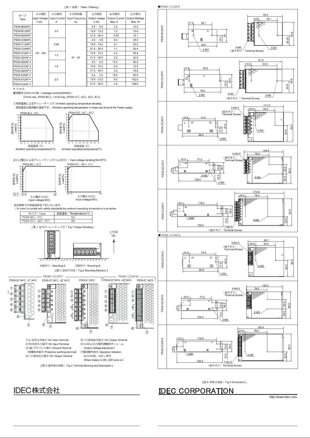
注意:取付には指定された取付穴を使用してください。
Note : Do not use other than designated mounting hole.
(取付穴 / Mounting hole)
(取付穴 / Mounting hole)
(取付穴 / Mounting hole)
(取付穴 / Mounting hole)
(取付穴 / Mounting hole)
(取付穴 / Mounting hole)
(取付穴 / Mounting hole)
(取付穴 / Mounting hole)
(取付穴 / Mounting hole)
(取付穴 / Mounting hole)
(取付穴 / Mounting hole)
(取付穴 / Mounting hole)
(取付穴 / Mounting hole)
(取付穴 / Mounting hole)
(取付穴 / Mounting hole)
(取付穴 / Mounting hole)
http://www.idec.com
本 社 〒532- 0004 大阪市淀川区西宮原2 - 6- 6 4 TE L :06 - 6 39 8 - 25 00
取扱説明書でご不明な点が御座いましたら、下記の技術問い合わせ窓口へお問い合わせ下さい。
お問い合わせ時間:
9:00~12:00 /13:00~17:00(土・日曜日、祝日および弊社休日を除く)
【技術問い合わせ窓口】
0120-992-336
■携帯電話・PHSの場合は050-8882-5843
2018.10
84-200-053R
1175 Elko Drive Sunnyvale, CA 94089, USA
Manufacturer: IDEC CORP.
2-6-64 Nishimiyahara Yodogawa-ku, Osaka 532-0004, Japan
EU Authorized Representative: APEM GmbH
Heselstuecken 8, 22453 Hamburg, GERMANY
This manual suits for next models
14
Other IDEC Power Supply manuals


