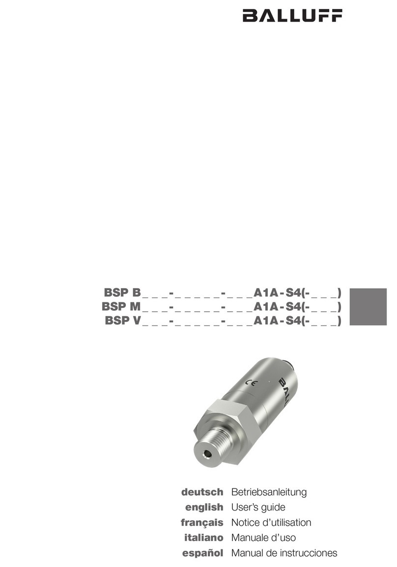
Balluff BSP-B-004-S1A Series User manual

www.balluff.com 1deutsch
Installation
Achtung!
Der Drucktransmitter darf keinen hohen Tempe-
raturen, schnellen Druckanstiegen über die
spezifischen Grenzen hinaus ausgesetzt werden
(Grenzwerte siehe Technische Daten).
– Die Drucktransmitter immer im druck- und stromlosen
Zustand montieren!
– Bei der Montage im Freien oder in feuchter Umgebung
ist Folgendes zu beachten:
Eine Montagelage auswählen, die ein Ablaufen von
Spritz- und Kondenswasser erlaubt. Stehende Flüssig-
keit an Dichtflächen ist auszuschließen!
Damit keine Feuchtigkeit in den Stecker eindringen
kann, das Gerät nach der Montage unmittelbar elek-
trisch anschließen. Anderenfalls den Feuchtigkeitsein-
tritt z.B. durch eine passende Schutzkappe verhindern.
Die im Datenblatt angegebene Schutzart gilt für das
angeschlossene Gerät!
Falls die Gefahr der Beschädigung durch Blitzeinschlag
oder Überspannung besteht, einen Überspannungs-
schutz zwischen Speisegerät bzw. Schaltschrank und
Gerät anordnen.
– Bei hydraulischen Systemen das Gerät so positionieren,
dass der Druckanschluss nach oben zeigt (Entlüftung).
– Beim Einsatz in Dampfleitungen eine Kühlstrecke vorsehen.
– Das Gerät so montieren, dass es vor direkter Sonnen-
einstrahlung geschützt ist. Diese kann die Funktions-
fähigkeit des Gerätes beeinträchtigen oder das Gerät
beschädigen.
– Ein Gerät mit Relativbezug im Gehäuse (kleine Bohrung
Transmittergehäuse) so montieren, dass der für die
Messung erforderliche Relativbezug vor
Schmutz und Feuchtigkeit geschützt ist. Falls das
Gerät einer Flüssigkeitsbeaufschlagung ausgesetzt
wird, ist der Luftdruckausgleich durch den Relativbe-
zug blockiert. Eine genaue Messung in diesem
Zustand ist nicht möglich. Außerdem kann es zu
Schäden am Gerät kommen.
– Durch die Montage dürfen keine mechanischen Span-
nungen am Druckanschluss auftreten, da diese zu
einer Verschiebung der Kennlinie führen können. Dies
gilt ganz besonders für sehr kleine Druckbereiche
sowie für Geräte mit einem Druckanschluss aus Kunst-
stoff.
EU-Richtlinie 2004/108/EG (EMV-Richtlinie) und EMV-Gesetz
Fachgrundnormen: EN 61000-6-4 (Emission), EN 61000-6-2 (Störfestigkeit)
Emissionsprüfungen: Funkstörstrahlung EN 55011 Gruppe 1, Klasse A und B
Bestimmungsgemäße Verwendung
Der Drucktransmitter wurde für die Drucküberwachung
von Gasen oder Flüssigkeiten etwickelt, die zu Edelstahl,
Keramik und FKM kompatibel sind. Je nach Gerät und
mechanischem Anschluss sind Drucktransmitter für unter-
schiedlichste Anwendungsbereiche geeignet.
Der Drucktransmitter wird zu seiner Verwendung in eine
Maschine oder Anlage eingebaut. Die einwandfreie Funk-
tion gemäß den Angaben in den technischen Daten wird
nur mit Original BALLUFF-Zubehör zugesichert, die
Verwendung anderer Komponenten bewirkt Haftungsaus-
schluss.
Veränderungen am Transmitter oder eine nicht bestim-
mungsgemäße Verwendung sind nicht zulässig und führen
zum Verlust von Gewährleistungs- und Haftungsansprü-
chen gegenüber dem Hersteller.
Sicherheitshinweise
Vor Inbetriebnahme ist die Betriebsanleitung
sorgfältig zu lesen!
Diese Sensoren dürfen nicht in Anwendungen
eingesetzt werden, in denen die Sicherheit von
Personen von der Gerätefunktion abhängt (kein
Sicherheitsbauteil gem. EU-Maschinenrichtlinie).
Die Installation und die Inbetriebnahme sind nur durch
geschultes Fachpersonal zulässig.
Der Betreiber hat die Verantwortung, dass die örtlich
geltenden Sicherheitsvorschriften eingehalten werden.
Insbesondere muss der Betreiber Maßnahmen treffen,
dass bei einem Defekt des Druckerfassungssystems keine
Gefahren für Personen und Sachen entstehen können.
Bei Defekten und nicht behebbaren Störungen des Sen-
sors ist dieser außer Betrieb zu nehmen und gegen unbe-
fugte Benutzung zu sichern.
Download der Betriebsanleitung
Die gleiche Betriebsanleitung erhalten Sie auch im Internet
unter www.balluff.com.
Gültigkeit
Diese Anleitung gilt für folgende Drucktransmitter:
– BSP-Bxxx-xx004-xxxS1A-xx
– BSP-Vxxx-xx004-xxxS1A-xx
Drucktransmitter IO-Link
BSP-Bxxx-xx004-xxxS1A-xx, BSP-Vxxx-xx004-xxxS1A-xx

2deutsch
Montage für Anschlüsse nach DIN 3852
Achten Sie darauf:
– dass die Dichtfläche des aufzunehmenden Teils eine
einwandfreie Oberfläche besitzt und keine Rückstände
vorhanden sind,
– dass der O-Ring unbeschädigt in der vorgesehenen
Nut sitzt.
1. Das Gerät mit der Hand in das Aufnahmegewinde
schrauben.
2. Geräte mit einer Schlüsselfläche auf dem Druck-
anschluss aus Stahl festschrauben. Beachten Sie die
nachfolgenden Drehmomente:
Installation
Drehmoment 1/4"
Anschluss
nach
EN 3852
Anschluss
nach
EN 837
NPT
Anschluss
R
Anschluss
ca. 5 Nm ca. 20 Nm
ca. 30 Nm ca. 30 Nm
Drehmoment 1/2"
Anschluss
nach
EN 3852
Anschluss
nach
EN 837
NPT
Anschluss
R
Anschluss
ca. 10 Nm ca. 50 Nm ca. 70 Nm ca. 70 Nm
Das Gerät entsprechend der auf dem Typenschild stehen-
den Angaben, der nachfolgenden Anschlussbelegungsta-
belle und dem Anschlussschaltbild elektrisch anschließen.
Achtung!
Den elektrischen Anschluss nur im druck- und
stromlosen Zustand durchführen.
Bild 1: Anschluss-Schaltbilder
Elektrische Anschlüsse
Elektrische
Anschlüsse
SIO Modus IO-Link Modus
Pin 1 Versorgung + Versorgung +
Pin 2 n.c. n.c.
Pin 3 Versorgung — Versorgung —
Pin 4 Out 1 IO-Link
Drucktransmitter IO-Link
BSP-Bxxx-xx004-xxxS1A-xx, BSP-Vxxx-xx004-xxxS1A-xx

www.balluff.com 3deutsch
Bild 2: Maßzeichnungen Drucktransmitter
Prozessanschluss
nach EN 3852
Maßzeichnungen
NPT-Prozessanschluss R-Prozessanschluss Prozessanschluss
nach EN 3852
Wartung
Eine falsche Reinigung kann zu irreparablen
Schäden an der Messzelle führen.
Benutzen Sie deshalb niemals spitze
Gegenstände oder Druckluft zum Reinigen der
Membrane.
Prinzipiell ist das Gerät wartungsfrei. Nach Bedarf kann
das Gehäuse des Gerätes im abgeschalteten Zustand mit
einem feuchten Tuch und einer nichtaggressiven Reini-
gungslösung gesäubert werden.
Je nach Messmedium kann es jedoch zu Ablagerungen
oder Vermutzungen auf der Membrane kommen. Ist eine
Neigung des Mediums bekannt, muss der Betreiber
entsprechende Reinigungsintervalle festlegen. Nach der
fachgerechten Außerbetriebnahme des Gerätes kann die
Membrane vorsichtig mit einer nichtaggressiven Reini-
gungslösung und einem weichen Pinsel oder Schwamm
gesäubert werden.
Außerbetriebnahme
Vom Messmedium kann eine Gefahr für den
Bediener ausgehen. Ergreifen Sie deshalb
geeignete Schutzmaßnahmen.
Demontieren Sie das Gerät immer im druck- und stromlo-
sen Zustand. Prüfen Sie vor der Demontage, ob ggf. das
Ablassen des Mediums erforderlich ist!
Entsorgung
Von den Rückständen des Mediums am Gerät
kann eine Gefahr für den Bediener und die
Umwelt ausgehen. Ergreifen Sie deshalb
geeignete Schutzmaßnahmen und entsorgen
Sie das Gerät sachgerecht.
Das Gerät ist gemäß der Europäischen Richtlinien
2002/96/EG und 2003/108/EG (Elektro- und Elektronik-
Altgeräte) zu entsorgen. Altgeräte dürfen nicht in den
Hausmüll gelangen!
Drucktransmitter IO-Link
BSP-Bxxx-xx004-xxxS1A-xx, BSP-Vxxx-xx004-xxxS1A-xx

4deutsch
IO-Link Interface
Allgemeine Device-Infos
Baudrate COM 2 (38,4 kBaud)
Prozessdatenlänge Eingang 2 byte
Minimale Zykluszeit 5 ms
IO-Link Version V1.1
SIO-Modus ja
SIO-Mode
Balluff Drucksensoren mit IO-Link unterstützen sowohl den
SIO-Modus, als auch den IO-Link Modus.
SIO-Modus (Standard IO-Modus)
Im SIO-Modus arbeitet der Sensor wie ein normaler
Drucksensor mit Standard-Ausgangssignalen.
Pin 4 (Ausgang 1) des M12 Steckers ist immer ein digitaler
Ausgang.
IO-Link Modus (Kommunikationsmodus)
Arbeitet der Sensor unter einem IO-Link Master, so wech-
selt der Drucksensor in den IO-Link Kommunikationsmo-
dus. Die IO-Link Kommunikation läuft nun über Pin 4 des
M12 Steckers.
Prozessdaten
Die Prozessdatenlänge des Drucksensors beträgt 16 Bit.
In den Prozessdaten werden die Schaltzustände des
beiden Schaltausgangs (BCD1), sowie der aktuelle
Messwert übertragen.
Die 14 Bit des Messwertes sind entsprechend des Mess-
bereichs des Sensors skaliert.
15....2 1 0
Messwert
BDC1/Ausgang 1
Error und Event Codes
Error Codes
Error Code Description
0x8011 Index not available
0x8012 Subindex not available
0x8023 Access Denied
0x8030 Parameter Value out of Range
0x8033 Paremeter length overrun
0x8034 Parameter length underrun
Event Codes
Definition Event-
Codes
IO-Link
1.1
Event-
Codes
IO-Link
1.0
Device
status
Type
No malfunction 0x0000 0x0000 0 Notifica-
tion
General mal-
function.
Unknown error
0x1000 0x1000 4 Error
Process
variable range
over-run.
Process Data
uncertain
0x8C10 0x8C10 2 Warning
Process
variable range
under-run.
Process Data
uncertain
0x8C30 0x8C10 2 Warning
Messbereich Wertebereich Multiplikator
–1...2 bar –1000...2000 x0,001
–1...10 bar –100...1000 x0,01
0...2 bar 0...2000 x0,001
0...5 bar 0...5000 x0,001
0...10 bar 0...1000 x0,01
0...20 bar 0...2000 x0,01
0...50 bar 0...5000 x0,01
0...100 bar 0...1000 x0,1
0...250 bar 0...2500 x0,1
0...400 bar 0...4000 x0,1
0...600 bar 0...6000 x0,1
Drucktransmitter IO-Link
BSP-Bxxx-xx004-xxxS1A-xx, BSP-Vxxx-xx004-xxxS1A-xx

www.balluff.com 5deutsch
Parameterdaten
Die Parameterdaten des Drucksensors entsprechen dem Smart Sensor Profil.
Index
hex
Subin-
dex hex
Object name Single Value Default Kommentar
0x02 0x00 System Com-
mands
0x81 = Löschen Min-/Max-Wert
0x82 = res
0xA0 = Set0
Durch Schreiben
in den Subindex
wird die Aktion
ausgeführt
0x03 0x00 Data Storage
Index
0x01: Upload Start
0x02: Upload End
0x03: Download Start
0x04: Download End
0x05: Datastorage Break
0x0C 0x00 Device Access
Lock
0x00: Unlocked
0x01: IO-Link Lock
0x02: Datastorage Lock
0x03: IO-Link Lock + Datastorage Lock
0x00:
Unlocked
0x24 0x00 Device status 0x00 Device is operating properly
0x02 Out-of-Specification
0x04 Failure
0x3D 0x02 SwitchPoint
mode
0x80: Hysteresis NO
0x81: Hysteresis NC
0x82: Window NO
0x83: Window NC
0x80: HNo
IO-Link Interface
Index
hex
Subindex
hex
Object name Access Length Value Range Gradi-
ent
Unit Default
0x3C 0x01 SetPoint 1 = SP1 R/W 2 Byte Process Data 100%
0x3C 0x02 SetPoint 2 = rP1 R/W 2 Byte Process Data 0%
0xD0 0x00 Delay Switching Time 1 R/W 2 Byte 0..500 0.1 sec 0
0xD1 0x00 Delay Back Switching Time 1 R/W 2 Byte 0..500 0.1 sec 0
0xD2 0x00 Delay Switching Time 2 R/W 2 Byte 0..500 0.1 sec 0
0xD3 0x00 Delay Back Switching Time 2 R/W 2 Byte 0..500 0.1 sec 0
0xD5 0x00 Min Pressure Value R 2 Byte Process Data
0xD6 0x00 Max Pressure Value R 2 Byte Process Data
0xD7 0x00 Measure damping R/W 2 Byte 0…1000
in 10 ms steps
1 ms 0
Drucktransmitter IO-Link
BSP-Bxxx-xx004-xxxS1A-xx, BSP-Vxxx-xx004-xxxS1A-xx

6deutsch
Elektrische Daten
Betriebsspannung UB12...32 V DC
Leerlaufstrom I0max ≤30 mA
Schnittstelle IO-Link V1.1
Verpolungssicher ja
Kurzschlussfest ja
Schaltfrequenz 200 Hz
Genauigkeit nach IEC 60770 ≤±0,5 % FSO BFSL
Temperaturfehler
bis 250 bar
ab 400 bar
≤±0,5 % FSO/10 K.
≤±0,3 % FSO/10 K
Mechanische Daten
Werkstoff Gehäuse Edelstahl 1.4301
Werkstoff Messzelle
bis 250 bar
ab 400 bar
Keramik Al203
Edelstahl 1.4542
Werkstoff Dichtring FKM
Anschluss Steckverbinder M12, 4-polig
Werkstoff Prozessanschluss
bis 250 bar
ab 400 bar
Edelstahl 1.4301
Edelstahl 1.4571
Prozessanschluss G 1/4", G 1/2",
1/4" NPT, R 1/4"
Gewicht ca. 120 g
Umgebungsbedingungen
Umgebungstemperatur –25...+85 °C
Medientemperatur –40...+125 °C
Schutzart nach IEC 60529 IP 67 in verschraub-
tem Zustand
Technische Daten
Ihr Drucktransmitter-Typ
Das Typenschild enthält die genaue Bezeichnung und die
wichtigsten technischen Daten, um das Gerät eindeutig zu
identifizieren.
Bestellcode Typenbezeichnung
elektr. Anschlüsse Nenndruck
rel. Nenndruck Überlastdruck Berstdruck
Sensor -1...2 bar 5 bar 10 bar
Sensor -1...10 bar 20 bar 35 bar
Sensor 0...2 bar 5 bar 10 bar
Sensor 0...5 bar 12 bar 15 bar
Sensor 0...10 bar 20 bar 35 bar
Sensor 0...20 bar 50 bar 70 bar
Sensor 0...50 bar 120 bar 150 bar
Sensor 0...100 bar 200 bar 300 bar
Sensor 0...250 bar 400 bar 750 bar
Sensor 0...400 bar 1200 bar 1500 bar
Sensor 0...600 bar 1200 bar 1800 bar
Drucktransmitter IO-Link
BSP-Bxxx-xx004-xxxS1A-xx, BSP-Vxxx-xx004-xxxS1A-xx
www.balluff.com 7deutsch
BSP - V 002 - F V 004 - D 06 S 1 A - S4 - T
Physikalische Einheit
M = Millibar
W = Millibar, Vakuum (ab –1 Bar)
B = Bar
V = Bar, Vakuum (ab –1 Bar)
K = Kilobar
Max. Druckbereich (Wert korrelliert mit phys. Einheit)
001 = 1
010 = 10
100 = 100
999 = 999
Prozessanschluss und Gehäuse
D = Außengewinde G1/4"
F = Außengewinde NPT 1/4"
H = Außengewinde G1/2"
K = Außengewinde G1/4"
Dichtung/Dichtsystem (BHS-Schlüssel beachten)
V = Dichtring Viton (ISO: FKM, DIN: FPM)
Gehäuseausführung
004 = Drucktransmitter
Schnittstelle zur SPS
D = Digitale Daten
Ausgangsfunktion/Ausgangstechnik
05 = 1 x NPN NO/NC umschaltbar
06 = 1 x PNP NO/NC umschaltbar
Variante/Optionen
S = IO-Link mit SIO Mode
Subvarinate bezogen auf Variante
1 = Basis Variante
Bedienelemente
A = keine Anzeige, keine Tasten
Steckersystem
S4 = M12, 4-polig
Besondere Eigenschaften/Sonderausführung (optional)
Z = Allgemeine Sonderausführung
T = temperaturbeständig
0 = generelle Sonderausführung
Typenschlüssel für Drucktransmitter
Drucktransmitter IO-Link
BSP-Bxxx-xx004-xxxS1A-xx, BSP-Vxxx-xx004-xxxS1A-xx
8deutsch
Nr. 929 450 DE .Ausgabe E16; Änderungen vorbehalten
Balluff GmbH
Industriestraße B16
2345 Brunn am Gebirge
Österreich
Tel. +43 2236 32521-0
Fax +43 2236 32521-46
nwww.balluff.com
Balluff Sensortechnik AG
Riedstrasse 6
8953 Dietikon
Schweiz
Tel. +41 43 3223240
Fax +41 43 3223241
nwww.balluff.com
Balluff GmbH
Schurwaldstraße 9
73765 Neuhausen a.d.F.
Deutschland
Tel. +49 7158 173-0
Fax +49 7158 5010
balluff@balluff.de
nwww.balluff.com
Drucktransmitter IO-Link
BSP-Bxxx-xx004-xxxS1A-xx, BSP-Vxxx-xx004-xxxS1A-xx

www.balluff.com 1English
Installation
Caution!
Do not allow the pressure transmitter to be
exposed to high temperatures or rapid
increases in pressure that extend beyond
specific limits (see Technical Data for limit
values).
– Always depressurize and disconnect pressure trans-
mitters from the power supply before installing!
– Observe the following when installing outdoors or in a
damp environment:
Select a installation location that allows splash and
condensation water to drain away. Fluids must not be
allowed to accumulate on sealing surfaces!
Connect the device to the power supply immediately
after installation to prevent moisture from entering the
connector. Otherwise fit a suitable protective cap to
prevent the ingress of moisture. The degree of protec-
tion specified on the data sheet only applies if the
device is connected!
If there is a risk of damage from lightning or excess
voltage, mount overvoltage protection between the
power supply unit or switching cabinet and device.
– On hydraulic systems, position the device so that the
pressure connection faces upwards (venting).
– If the device is installed on a steam pipeline, provide a
cooling section.
– Mount the device in a location protected from direct
sunlight. Sunlight can damage or affect the functional
capability of the device.
– When installing devices with a gauge reference in the
housing (small hole in the transmitter housing), make
sure that the gauge reference required for the mea-
surement is protected against dirt and moisture. If the
device is exposed to fluids, the gauge reference blocks
the air pressure compensator. Accurate measurements
are not possible when this happens. and the device
may be damaged.
– No mechanical tension should be placed on the pres-
sure connection during installation as this may shift the
characteristic curve. This applies in particular to
extremely small pressure ranges and devices with a
plastic pressure connection.
EU Directive 2004/108/EC (EMC Directive) and EMC Law
Generic Standards: EN 61000-6-4 (Emissions), EN 61000-6-2 (Interference Immunity)
Emissions testing: Radio interference emissions EN 55011 Group 1, Class A and B
Intended use
The pressure transmitter has been developed to monitor
the pressure of gases or fluids compatible with stainless
steel, ceramics and fluoroelastomers. Pressure transmit-
ters are suited to different types of application depending
on the device and mechanical connection.
The pressure transmitter is installed in a machine or inte-
grated into a system. Flawless function in accordance with
the specifications in the technical data is ensured only
when using original BALLUFF accessories, and use of any
other components will void the warranty.
Modifications to the transmitter or non-approved use are
not permitted and will result in loss of warranty and void
any liability claims against the manufacturer.
Safety instructions
Before commissioning, read the user's guide
carefully!
These sensors must not be used in applications
in which the safety of persons is dependent on
the function of the device (not a safety compo-
nent acc. to EU Machinery Directive).
Installation and startup are to be performed only by
trained specialists.
The operator is responsible for ensuring that local safety
regulations are observed.
In particular, the operator must take measures to ensure
that a defect in the pressure detection system will not
result in hazards to persons or equipment.
If defects or non-clearable faults in the sensor occur, take it
out of service and secure against unauthorized use.
Downloading the user's guide
The user's guide can also be found on the Internet at
www.balluff.com.
Validity
This guide is valid for the following pressure transmitters:
– BSP-Bxxx-xx004-xxxS1A-xx
– BSP-Vxxx-xx004-xxxS1A-xx
Pressure Transmitters with IO-Link
BSP-Bxxx-xx004-xxxS1A-xx, BSP-Vxxx-xx004-xxxS1A-xx

2English
Installation of connections according to DIN 3852
Make sure that:
– The sealing surface on the relevant part is perfectly
clean and free of residue.
– The O-ring seated in the slot provided is undamaged.
1. Screw the device into the mounting thread by hand.
2. Secure devices to the steel pressure connection using
a flat wrench. Observe the following torque values:
Installation
Torque 1/4"
Connec-
tion per
EN 3852
Connection
per
EN 837
NPT con-
nection
R
connec-
tion
approx. 5
Nm
approx. 20
Nm
approx. 30
Nm
approx. 30
Nm
Torque 1/2"
Connec-
tion per
EN 3852
Connection
per
EN 837
NPT con-
nection
R
connec-
tion
approx. 10
Nm
approx. 50
Nm
approx. 70
Nm
approx. 70
Nm
Establish the electrical connection to the device according
to the specifications indicated on the type plate, the pin
assignment table below and the wiring diagram.
Caution!
Always depressurize and disconnect devices
from the power supply before establishing an
electrical connection.
Image 1: Wiring diagram
Electrical connections
Electrical
connections
SIO Mode IO-Link Mode
Pin 1 Supply + Supply +
Pin 2 n.c. n.c.
Pin 3 Power supply – / Power Supply –
Pin 4 Out 1 IO-Link
Pressure Transmitters with IO-Link
BSP-Bxxx-xx004-xxxS1A-xx, BSP-Vxxx-xx004-xxxS1A-xx

www.balluff.com 3English
Image 2: Dimensioned drawing of pressure transmitter
Process connection
per EN 3852
Dimensional drawings
NPT process connection R process connection Process connection
per EN 3852
Maintenance
Incorrect cleaning can cause irreparable dam-
age to the measuring cell.
Therefore never use pointed objects or com-
pressed air to clean the membrane.
The device is maintenance-free in principle. If required, the
housing can be cleaned with a damp cloth and mild
cleaning solution provided the device is switched off.
The membrane may become covered with deposits and
contamination, depending on the measuring material. If the
nature of the material is known, the operator must define
appropriate cleaning intervals. When the device is decom-
missioned correctly, the membrane can be cleaned care-
fully with a mild cleaning solution and a soft brush or
sponge.
Decommissioning
The measuring material may pose a risk to the
operator. Therefore always take appropriate
protective measures.
Always depressurize and disconnect the device from the
power supply before removing and check whether material
must be drained first!
Disposal
Residual material on the device may pose a risk
to the operator and a danger to the environ-
ment. Therefore always take appropriate protec-
tive measures and dispose of the device cor-
rectly.
The device must be disposed of according to European
Directives 2002/96/EC and 2003/108/EC (Waste Electrical
and Electronic Equipment). Equipment should be disposed
of separately from household waste!
Pressure Transmitters with IO-Link
BSP-Bxxx-xx004-xxxS1A-xx, BSP-Vxxx-xx004-xxxS1A-xx

4English
IO-Link interface
General device info
Baud rate COM 2 (38.4 kbaud)
Input of process data length 2 bytes
Minimum cycle time 5 ms
IO-Link version V1.1
SIO Mode Yes
SIO Mode
Balluff pressure sensors with IO-Link support both SIO
Mode and IO-Link Mode.
SIO Mode (standard IO mode)
In SIO Mode, the sensor works like a normal pressure
sensor with standard output signals.
Pin 4 (output 1) of the M12 plug is always a digital output.
An additional digital output or an analog output is available
on pin 2 (output 2), depending on the selected version.
IO-Link Mode (communication mode)
If the sensor operates subordinate to an IO-Link master,
then the pressure sensor switches to IO-Link communica-
tion mode. The IO-Link communication now runs via pin 4
of the M12 plug.
Process data
The process data length of the pressure sensor is 16 bits.
The switching statuses of the two switching outputs
(BCD1 and BCD2) are transmitted in the process data, as
well as the current measured value.
The 14 bits of the measured value are scaled correspond-
ing to the measuring range of the sensor.
15....2 1 0
Measured value
BDC1/Output 1
Error and event codes
Error codes
Error code Description
0x8011 Index not available
0x8012 Subindex not available
0x8023 Access denied
0x8030 Parameter value out of range
0x8033 Parameter length overrun
0x8034 Parameter length underrun
Event codes
Definition Event
codes
IO-Link
1.1
Event
codes
IO-Link
1.0
Device
status
Type
No malfunction 0x0000 0x0000 0 Notifica-
tion
General mal-
function.
Unknown error
0x1000 0x1000 4 Error
Process
variable range
overrun.
Process data
uncertain
0x8C10 0x8C10 2 Warning
Process
variable range
underrun.
Process data
uncertain
0x8C30 0x8C10 2 Warning
Measuring
range
Value range Multiplier
–1...2 bar –1000...2000 x0.001
–1...10 bar –100...1000 x0.01
0...2 bar 0...2000 x0.001
0...5 bar 0...5000 x0.001
0...10 bar 0...1000 x0.01
0...20 bar 0...2000 x0.01
0...50 bar 0...5000 x0.01
0...100 bar 0...1000 x0.1
0...250 bar 0...2500 x0.1
0...400 bar 0...4000 x0.1
0...600 bar 0...6000 x0.1
Pressure Transmitters with IO-Link
BSP-Bxxx-xx004-xxxS1A-xx, BSP-Vxxx-xx004-xxxS1A-xx

www.balluff.com 5English
Parameterization data
The pressure sensor parameter data corresponds to the smart sensor profile.
Index
hex
Subin-
dex hex
Object name Single Value Default Comment
0x02 0x00 System Com-
mands
0x81 = Deleting Min./Max. value
0x82 = res
0xA0 = Set0
The action is
carried out by
writing in the
subindex.
0x03 0x00 Data Storage
Index
0x01: Upload Start
0x02: Upload End
0x03: Download Start
0x04: Download End
0x05: Datastorage Break
0x0C 0x00 Device Access
Lock
0x00: Unlocked
0x01: IO-Link Lock
0x02: Datastorage Lock
0x03: IO-Link Lock + Datastorage Lock
0x00:
Unlocked
0x24 0x00 Device status 0x00 Device is operating properly
0x02 Out-of-Specification
0x04 Failure
0x3D 0x02 SwitchPoint
mode
0x80: Hysteresis NO
0x81: Hysteresis NC
0x82: Window NO
0x83: Window NC
0x80: HNo
IO-Link interface
Index
hex
Subindex
hex
Object name Access Length Value Range Gradi-
ent
Unit Default
0x3C 0x01 SetPoint 1 = SP1 R/W 2 Byte Process Data 100%
0x3C 0x02 SetPoint 2 = rP1 R/W 2 Byte Process Data 0%
0xD0 0x00 Delay Switching Time 1 R/W 2 Byte 0..500 0.1 sec 0
0xD1 0x00 Delay Back Switching Time 1 R/W 2 Byte 0..500 0.1 sec 0
0xD2 0x00 Delay Switching Time 2 R/W 2 Byte 0..500 0.1 sec 0
0xD3 0x00 Delay Back Switching Time 2 R/W 2 Byte 0..500 0.1 sec 0
0xD5 0x00 Min Pressure Value R 2 Byte Process Data
0xD6 0x00 Max Pressure Value R 2 Byte Process Data
0xD7 0x00 Measure damping R/W 2 Byte 0…1000
in 10 ms steps
1 ms 0
Pressure Transmitters with IO-Link
BSP-Bxxx-xx004-xxxS1A-xx, BSP-Vxxx-xx004-xxxS1A-xx

6English
Electrical data
Supply voltage US12...32 V DC
No-load supply current I0max ≤30 mA
Interface IO-Link V1.1
Polarity reversal protected Yes
Short-circuit protected Yes
Switching frequency f 200 Hz
Accuracy according to IEC
60770
≤±0.5% FSO BFSL
Temperature error
up to 250 bar
from 400 bar
≤±0.5% FSO/10 K.
≤±0.3% FSO/10 K
Mechanical data
Housing material Stainless steel 1.4301
Measuring cell material
up to 250 bar
from 400 bar
Ceramics Al203
Stainless steel 1.4542
Sealing ring material Fluoroelastomer
Plug connector socket M12, 4-pin
Process connection for material
up to 250 bar
from 400 bar
Stainless steel 1.4301
Stainless steel 1.4571
Process connection G 1/4", G 1/2",
1/4" NPT, R 1/4"
Weight Approx. 120 g
Ambient conditions
Ambient temperature range –40...+85 °C
Material temperature –40...+125 °C
Degree of protection as per
IEC 60529
IP 67 when connected
Technical data
Your pressure transmitter type
The type plate contains the exact designation and most
important technical data so that the device can be identi-
fied clearly.
Ordering code Part number
Electr. connections Nominal pressure
rel. nominal
pressure
Overload
pressure
Cracking
pressure
Sensor –1...2 bar 5 bar 10 bar
Sensor –1...10 bar 20 bar 35 bar
Sensor 0...2 bar 5 bar 10 bar
Sensor 0...5 bar 12 bar 15 bar
Sensor 0...10 bar 20 bar 35 bar
Sensor 0...20 bar 50 bar 70 bar
Sensor 0...50 bar 120 bar 150 bar
Sensor 0...100 bar 200 bar 300 bar
Sensor 0...250 bar 400 bar 750 bar
Sensor 0...400 bar 1200 bar 1500 bar
Sensor 0...600 bar 1200 bar 1800 bar
Pressure Transmitters with IO-Link
BSP-Bxxx-xx004-xxxS1A-xx, BSP-Vxxx-xx004-xxxS1A-xx

www.balluff.com 7English
BSP - V 002 - F V 004 - D 06 S 1 A - S4 - T
Physical unit
M = millibar
W = millibar, vacuum (from –1 bar)
B = bar
V = bar, vacuum (from –1 bar)
K = kilobar
Max. pressure range (value correlates with phys. unit)
001 = 1
010 = 10
100 = 100
999 = 999
Process connection and housing
D = external thread G1/4"
F = external thread NPT 1/4"
H = external thread G1/2"
K = external thread G1/4"
Seal/sealing system (see BHS code)
V = Viton sealing ring (ISO: FKM, DIN: FPM)
Housing type
004 = pressure transmitter
Interface to PLC
D = digital data
Output function/output technology
05 = 1 x NPN, NO/NC selection
06 = 1 x PNP, NO/NC selection
Variant/options
S = IO-Link with SIO Mode
Subversions based on main version
1 = Basic variant
Operating elements
A = no display, no buttons
Connector system
S4 = M12, 4-pin
Special characteristics or design (optional)
Z = General special design
T = Temperature-resistant
0 = Basic special design
Type code for pressure transmitters
Pressure Transmitters with IO-Link
BSP-Bxxx-xx004-xxxS1A-xx, BSP-Vxxx-xx004-xxxS1A-xx

8English
No. 929 450 EN .Edition F16; Subject to modification
Balluff GmbH
Industriestrasse B16
2345 Brunn am Gebirge
Austria
Phone +43 2236 32521-0
Fax +43 2236 32521-46
nwww.balluff.com
Balluff Sensortechnik AG
Riedstrasse 6
8953 Dietikon
Switzerland
Phone +41 43 3223240
Fax +41 43 3223241
nwww.balluff.com
Balluff GmbH
Schurwaldstrasse 9
73765 Neuhausen a.d.F.
Germany
Phone +49 7158 173-0
Fax +49 7158 5010
balluff@balluff.de
nwww.balluff.com
Pressure Transmitters with IO-Link
BSP-Bxxx-xx004-xxxS1A-xx, BSP-Vxxx-xx004-xxxS1A-xx

www.balluff.com 1español
Instalación
¡Atención!
No se debe exponer el transmisor de presión a
altas temperaturas o rápidos aumentos de
presión más allá de los límites específicos (ver
los datos técnicos para los valores límite).
– ¡Montar los transmisores de presión siempre en estado
sin presión y sin corriente!
– En caso de montaje al aire libre o en un entorno
húmedo debe tenerse en cuenta lo siguiente:
Elegir una posición de montaje que permita la evacua-
ción de agua proyectada y de agua de condensación.
¡Se debe excluir cualquier posibilidad de que se forme
un líquido estático en las superficies obturadoras!
Para evitar que penetre humedad en el conector,
conectar el aparato eléctricamente inmediatamente
después del montaje. De lo contrario, prevenir la
entrada de humedad, por ejemplo, mediante una
caperuza protectora adecuada. ¡El grado de protec-
ción indicado en la hoja de datos es aplicable al apa-
rato conectado!
En caso de que exista peligro de sufrir daños debido a
un rayo o una sobretensión, debe disponerse una
protección contra sobretensión entre el aparato de
alimentación o el armario de distribución y el aparato.
– En caso de sistemas hidráulicos debe posicionarse el
aparato de tal modo que la conexión de presión esté
orientada hacia arriba (purga de aire).
– En caso de empleo en tuberías de vapor debe pre-
verse un trayecto de refrigeración.
– Montar el aparato de tal modo que esté protegido
contra la radiación solar directa. Ésta puede perjudicar
la capacidad de funcionamiento del aparato o dañar el
aparato.
– Un aparato con una referencia relativa en la carcasa
(taladro pequeño en la carcasa del transmisor) debe
montarse de tal modo que la referencia relativa nece-
saria para la medición esté protegida frente a la sucie-
dad y humedad. Si el aparato está expuesto a una
aplicación de líquido, la compensación de la presión
de aire queda bloqueada por la referencia relativa. En
este estado no es posible efectuar una medición
exacta. Además pueden producirse daños en el aparato.
– Debido al montaje no deben producirse tensiones
mecánicas en la conexión de presión ya que pueden
provocar un desplazamiento de la curva característica.
Esto es especialmente aplicable a gamas de presión
muy pequeñas, así como a aparatos con una conexión
de presión de plástico.
Directiva UE 2004/108/CE (directiva CEM) y ley CEM
Normas genéricas: EN 61000-6-4 (emisiones), EN 61000-6-2 (resistencia a interferencias)
Pruebas de emisiones: emisiones radioeléctricas EN 55011 grupo 1, clase A y B
Utilización conforme al uso previsto
El transmisor de presión ha sido desarrollado para la
supervisión de presión de gases o líquidos que son com-
patibles con acero fino, cerámica y FKM. En función del
aparato y la conexión mecánica, los transmisores de
presión resultan adecuados para las áreas de aplicación
más variadas.
El transmisor de presión debe montarse en una máquina o
instalación para poder utilizarlo. El funcionamiento correcto
según las indicaciones en los datos técnicos sólo se
garantiza en el caso de utilizar accesorios originales de
BALLUFF. La utilización de otros componentes conlleva la
exoneración de responsabilidad.
Las modificaciones en el transmisor o una utilización
indebida no son admisibles e implican la pérdida de todos
los derechos de garantía y responsabilidad frente al fabri-
cante.
Indicaciones de seguridad
¡Antes de la puesta en servicio deben leerse
detenidamente las instrucciones de servicio!
Estos sensores no deben utilizarse en aplicacio-
nes en las que la seguridad de las personas
dependa de la función del aparato (no se trata
de un componente de seguridad según la
directiva europea sobre máquinas).
Solo personal técnico cualificado debe realizar la instala-
ción y puesta en servicio.
El dueño es responsable de que se cumplan las prescrip-
ciones de seguridad locales vigentes.
Especialmente se trata de que el dueño tome medidas de
modo que en caso de defecto del sistema de captación
de presión no se puedan producir peligros para las perso-
nas ni los bienes materiales.
En caso de defectos y anomalías del sensor que no se
puedan eliminar, debe ponerse fuera de funcionamiento y
asegurarlo contra uso no autorizado.
Descarga de las instrucciones de servicio
También puede obtener las mismas instrucciones de
servicio en Internet en www.balluff.com.
Validez
Estas instrucciones son aplicables a los siguientes trans-
misores de presión:
– BSP-Bxxx-xx004-xxxS1A-xx
– BSP-Vxxx-xx004-xxxS1A-xx
Sensores de presión con IO-Link
BSP-Bxxx-xx004-xxxS1A-xx, BSP-Vxxx-xx004-xxxS1A-xx

2español
Montaje para conexiones según DIN 3852
Prestar atención a que:
– La superficie obturadora de la pieza receptora tenga
una superficie impecable y que no existan restos.
– La junta tórica se encuentra asentada intacta en la
ranura prevista.
1. Enroscar el aparato con la mano en la rosca de aloja-
miento.
2. Atornillar los aparatos con una superficie de llave sobre
la conexión de presión de acero. Tener en cuenta los
siguientes pares:
Instalación
Par 1/4"
Conexión
según
EN 3852
Conexión
según
EN 837
Conexión
NPT
Conexión
R
Aproximada-
mente 5 Nm
Aproximada-
mente 20 Nm
Aproximada-
mente 30 Nm
Aproximada-
mente 30 Nm
Par 1/2"
Conexión
según
EN 3852
Conexión
según
EN 837
Conexión
NPT
Conexión
R
Aproximada-
mente 10 Nm
Aproximada-
mente 50 Nm
Aproximada-
mente 70 Nm
Aproximada-
mente 70 Nm
Conectar el aparato eléctricamente según las indicaciones
que figuran en la placa de características, la siguiente tabla
de conexionado y el esquema eléctrico de conexión.
¡Atención!
Realizar la conexión eléctrica solo en estado sin
presión y sin corriente.
Figura 1: esquemas de conexión
Conexiones eléctricas
Conexiones
eléctricas
Modo SIO Modo IO-Link
Pin 1 Alimentación + Alimentación +
Pin 2 n.c. n.c.
Pin 3 Alimentación — Alimentación —
Pin 4 Out 1 IO-Link
Sensores de presión con IO-Link
BSP-Bxxx-xx004-xxxS1A-xx, BSP-Vxxx-xx004-xxxS1A-xx

www.balluff.com 3español
Figura 2: dibujos a escala de transmisores de presión
Conexión de proceso
según EN 3852
Dibujos a escala
Conexión de proceso
NPT
Conexión de proceso R Conexión de proceso
según EN 3852
Mantenimiento
Una limpieza incorrecta puede provocar daños
irreparables en la célula de medición.
Por tanto, jamás utilice objetos con punta o aire
a presión para limpiar la membrana.
En principio, el aparato no requiere mantenimiento. Según
necesidad puede limpiarse la carcasa del aparato en
estado apagado con un paño húmedo y una solución de
limpieza no agresiva.
No obstante, en función del medio de medición pueden
producirse acumulaciones o acumularse impurezas sobre
la membrana. Si se conoce alguna tendencia del medio, el
dueño deberá determinar los correspondientes intervalos
de limpieza. Después de la correcta puesta fuera de
servicio del aparato puede limpiarse la membrana cuida-
dosamente con una solución de limpieza no agresiva y un
pincel blando o una esponja.
Puesta fuera de servicio
Del medio de medición puede emanar un
peligro para el operario. Por tanto debe tomar
las medidas de protección adecuadas.
Desmonte el aparato siempre en estado sin presión y sin
corriente. ¡Compruebe antes del desmontaje si a lo mejor
se requiere la evacuación del medio!
Eliminación
De los restos del medio en el aparato puede
emanar un peligro para el operario y el medio
ambiente. Por tanto debe tomar medidas de
protección adecuadas y desechar el aparato
correctamente.
El aparato debe desecharse según las directivas europeas
2002/96/CE y 2003/108/CE (residuos de aparatos eléctri-
cos y electrónicos). ¡Los aparatos residuales no deben
echarse a las basuras domésticas!
Sensores de presión con IO-Link
BSP-Bxxx-xx004-xxxS1A-xx, BSP-Vxxx-xx004-xxxS1A-xx

4español
Interfaz IO-Link
Información general de dispositivo
Velocidad de baudios COM 2 (38,4 Kbaudios)
Longitud de datos de proceso
entrada
2 bytes
Tiempo de ciclo mínimo 5 ms
Versión IO-Link V1.1
Modo SIO Sí
Modo SIO
Los sensores de presión de Balluff con IO-Link soportan
tanto el modo SIO como también el modo IO-Link.
Modo SIO (modo IO estándar)
En el modo SIO, el sensor funciona como un sensor de
presión normal con señales de salida estándar.
El pin 4 (salida 1) del conector M12 siempre es una salida
digital y en el pin 2 (salida 2) se encuentra a disposición
otras salida digital o una salida analógica en función de la
versión seleccionada
Modo IO-Link (modo de comunicación)
Si el sensor funciona con un maestro IO-Link, el sensor de
presión cambia al modo de comunicación IO-Link. La
comunicación IO-Link funciona ahora a través del pin 4 del
conector M12.
Datos de proceso
La longitud de datos de proceso del sensor de presión es
de 16 bits. En los datos de proceso se transmiten tanto
los estados de conexión de las dos salidas de conmuta-
ción (BCD1 y BCD2), así como el valor de medición actual.
Los 14 bits del valor de medición están escalonados de
forma correspondiente al rango de medición del sensor.
15....2 1 0
Valor de medición
BDC1/salida 1
Códigos de error y evento
Códigos de error
Código de error Descripción
0x8011 Index not available
0x8012 Subindex not available
0x8023 Access Denied
0x8030 Parameter Value out of Range
0x8033 Parameter length overrun
0x8034 Parameter length underrun
Códigos de evento
Definición Event-
Codes
IO-Link
1.1
Event-
Codes
IO-Link
1.0
Device
status
Type
No malfunction 0x0000 0x0000 0 Notifica-
tion
General mal-
function.
Unknown error
0x1000 0x1000 4 Error
Process
variable range
over-run.
Process Data
uncertain
0x8C10 0x8C10 2 Warning
Process
variable range
under-run.
Process Data
uncertain
0x8C30 0x8C10 2 Warning
Rango de medi-
ción
Gama de valo-
res
Multiplicador
–1...2 bar –1000...2000 x0,001
–1...10 bar –100...1000 x0,01
0...2 bar 0...2000 x0,001
0...5 bar 0...5000 x0,001
0...10 bar 0...1000 x0,01
0...20 bar 0...2000 x0,01
0...50 bar 0...5000 x0,01
0...100 bar 0...1000 x0,1
0...250 bar 0...2500 x0,1
0...400 bar 0...4000 x0,1
0...600 bar 0...6000 x0,1
Sensores de presión con IO-Link
BSP-Bxxx-xx004-xxxS1A-xx, BSP-Vxxx-xx004-xxxS1A-xx
This manual suits for next models
1
Table of contents
Languages:
Other Balluff Transmitter manuals
Popular Transmitter manuals by other brands

GF
GF Signet 8850-3 manual

Bell
Bell RT-66/GRC Technical manual

Becker
Becker Centronic TimeControl TC4410-II Assembly and operating instructions

EUTECH INSTRUMENTS
EUTECH INSTRUMENTS ALPHA PH 1000 PHORP CONTROLLERTRANSMITTER instruction manual

MONARCH INSTRUMENT
MONARCH INSTRUMENT TRACK-IT instruction manual

Powercast
Powercast Powercaster TX91501B user manual