MONARCH INSTRUMENT TRACK-IT User manual

Instruction Manual
Track-It™Pressure Transmitter
with Digital Display
15 Columbia Drive
Amherst, NH 03031 USA
Phone: (603) 883-3390 • Fax: (603) 886-3300
E-mail: [email protected]
Website: www.monarchinstrument.com

SAFEGUARD AND PRECAUTIONS
1. Read and follow all instrucons in this manual carefully, and retain this manual
for future reference.
2. Do not open the unit in a high humidity environment; it will cause condensaon
inside the unit.
3. Do not operate this device in ammable or explosive atmospheres.
4. This device has no power switch. It will be in operaon as soon as power is
connected.
5. Do not use this instrument in any manner inconsistent with these operang
instrucons or under any condions that exceed the environmental
specicaons stated.
6. There are no user serviceable parts in this instrument. Refer service to a
qualied technician.
In order to comply with EU Direcve 2012/19/EU on Waste Electrical and
Electronic Equipment (WEEE): This product may contain material which
could be hazardous to human health and the environment. DO NOT
DISPOSE of this product as unsorted municipal waste. This product needs to be
RECYCLED in accordance with local regulaons; contact your local authories for
more informaon. This product may be returnable to your distributor for recycling;
contact the distributor for details.
Monarch Instrument’s Limited Warranty applies.
See www.monarchinstrument.com for details.
Warranty Registraon and Extended Warranty Coverage informaon is available
online at www.monarchinstrument.com.
Track-It is a trademark of Monarch Instrument.
Android and Google Play are trademarks of Google Inc.
The Android robot is reproduced or modied from work created and shared by Google and used
according to terms described in the Creave Commons 3.0 Aribuon License.
Excel is either a registered trademark or trademark of Microso Corporaon in the United States
and/or other countries.
Copyright 2016-2021 Monarch Instrument, All rights reserved

TABLE OF CONTENTS
1.0 INTRODUCTION .............................................................. 1
2.0 GETTING STARTED ........................................................... 2
2.1 InstallUSBDriverandTrack-ItSoware..................2
2.2 ConnectTransmierandStartTrack-ItSoware....3
2.3 CongureTransmier............................................3
3.0 INSTALLATION.................................................................4
3.1 Vent........................................................................4
4.0 POWER/TRANSMITTERCONNECTIONS...........................5
5.0 BUTTONSANDMENU.....................................................7
5.1 MenuModes..........................................................7
5.2 MenuOpons........................................................8
6.0 LCD .............................................................................. 10
7.0 LED ..............................................................................12
8.0 TRACK-ITPCSOFTWARE................................................12
8.1 Preferences...........................................................13
8.2 InputSetup..........................................................14
8.3 OutputSetup.......................................................14
8.4 DisplaySetup.......................................................15
8.5 MenuSetup.........................................................16
9.0 TRACK-ITTRANSPORTAPP............................................17
10.0 SPECIFICATIONS...........................................................17
10.1 Measurement......................................................17
10.2 General..............................................................18
10.3 IsolatedCurrentOutput.....................................19
10.4 OperangEnvironment.......................................19
10.5 Compliance.........................................................20
11.0 ACCESSORIES ................................................................ 20

1.0 DESCRIPTION
The Track-It Pressure Transmier with Display is a 24V DC powered
waterght (IP65) compact data logger with an isolated 4 to 20mA current
transmier output for pressure.
It can be congured to record both pressure and temperature up to 130,000
samples or pressure alone, to maximize data storage space. Real-me
data, alarms, and min/max informaon can be displayed on the mulline
LCD. The pressure transmier output current (4-20mA) can be scaled by
the user to provide maximum resoluon over the desired pressure span.
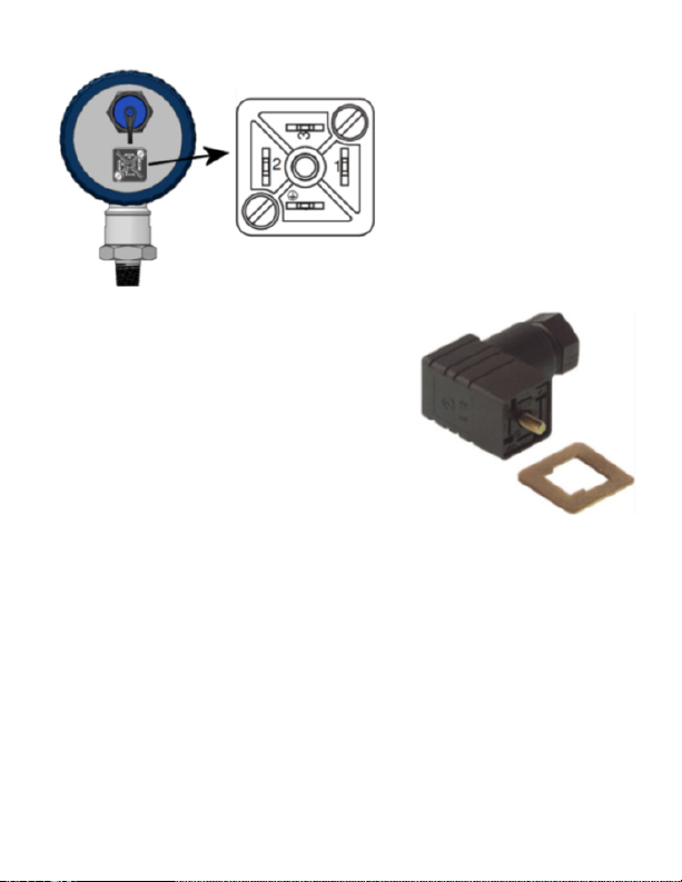
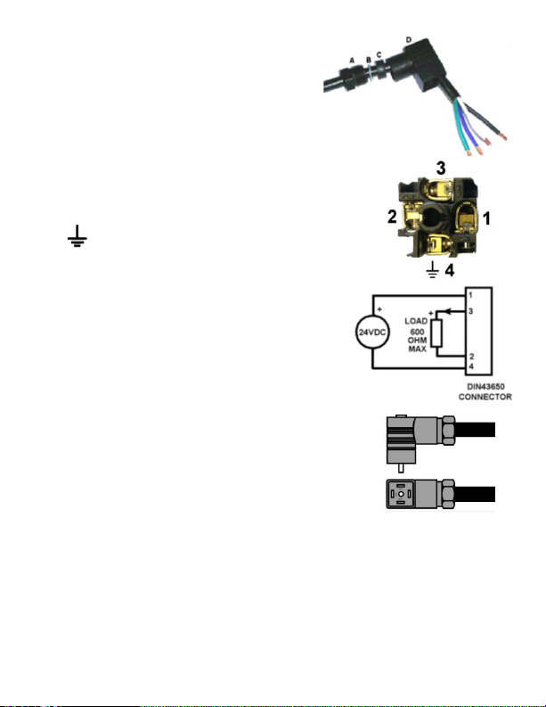
Power and mA out connecon is via a 4 pin DIN 43650 IP65 connector on
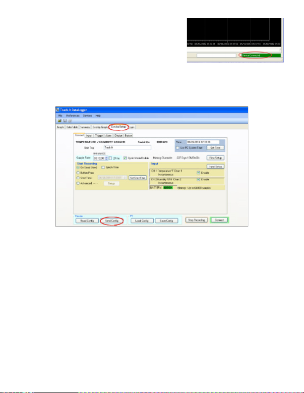
the rear panel. The unit is easily congured using the free downloadable
Track-It™ PC Soware. There is a mini USB connector on the rear of the unit
allowing connecon to a PC for programming and data download. Data
download can also be done with an Android™ device using the Transporter
App available on the Google Play™ store.
The Transmier can be programmed to record data from once every
two seconds to once a day. The recording can be iniated by the user
to commence immediately, manually via the keypad buons, at some
preset me in the future, or on an alarm condion. Current output does
not depend on record rate or sample rate; it updates in real-me at
approximately 8 mes per second.
The display can be programmed to display pressure in various engineering
units depending on pressure range. It can also display temperature,
minimum and maximum values, percentage of memory used, me and
date.
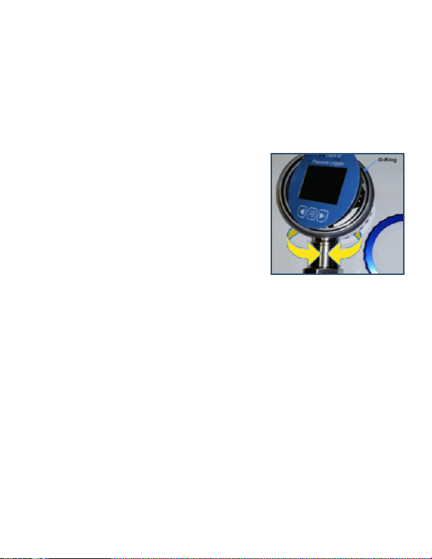
The Track-It Pressure Transmier with Display has a rugged waterght
anodized aluminum and stainless steel housing. The pressure sensor has a
standard ¼"-NPT or ½"-NPT ng.
1

2.0 GETTING STARTED
2.1 InstallUSBDriverandTrack-ItSoware
IMPORTANT:DoNOTplugtheTrack-ItPressureTransmierintothe
USBportunlAFTERtheUSBDriverandTrack-ItSowarehavebeen
installed.
Download Track-It Data Logger Soware from:
hp://www.monarchinstrument.com/Soware/Track_It_Soware.zip
Unzip the downloaded le to a local directory on your PC.
Double-click CD_Start.exe. This will launch the Track-It Data Loggers
installaon screen shown right:
1. Click Install the USB Driver and follow
the prompts. Click Connue Anyway if
you see the message about soware
installaon.
2. Click Install Soware and follow the
instrucons to complete the installaon.
The soware is now ready for use.
Logger and soware manuals may also be accessed from the installaon
screen.
2.2 ConnectTransmier andStartTrack-ItSoware
Plug the Track-It Pressure Transmier into an available USB port on
the PC using the supplied cable. If the Found New Hardware Wizard
appears, follow the prompts to complete the installaon.
Start the Track-It Soware by double-clicking the Track-It icon on
your PC desktop or from the Start menu.
2

3
If the USB driver is installed properly, you
will see Device Connected displayed in the
lower right-hand corner of the Track-It
Soware window.
2.3CongureTransmier
Select the Device Setup tab as shown below. The soware will
automacally retrieve and display the transmier conguraon.
Review default factory conguraon sengs and make any necessary
changes — sample rates, triggers, alarms, etc. Be sure that the me
and date is set properly.
Click the Send Cong buon under the Device Conguraon secon of
the window. Your Pressure Transmier is now operaonal!

4
3.0INSTALLATION
The Pressure Transmier can be ordered with various pressure sensor
ranges to cover most applicaons. Sensors have a ¼" NPT or ½"-NPT
thread, dependent on pressure range, that is intended to screw into the
pressure source. Make sure to use suitable tape or thread sealant/dope
on the threads before inserng the Transmier into the port. Use an
adjustable wrench on the SENSOR NUT to ghten the device into the port
and test for leaks.
Once installed the dial can be rotated 300
degrees about the sensor to the intended
viewing direcon. The gauge face can also
be rotated ±90 degrees by undoing the blue
bezel, liing the front panel and associated
electronics and rotang it to the desired
posion. Ensure the gasket/o-ring is in place
before replacing the bezel. Do not stress any of
the internal wiring.
3.1Vent
All gauge (PSIG) sensors are vented to atmosphere through a small hole
on the rear cover. DO NOT cover or block the vent or the transmier
may read incorrectly. DO NOT insert anything into the vent hole as it
may damage the waterproof membrane.

5
4.0POWER/TRANSMITTERCONNECTIONS
The transmier has a 4-pole
DIN43650 connector on the
rear panel for power and
current out connecons.
A mang plug (Hirschmann GDS 307) and
at gasket (Hirschmann GDS 307-4) are
supplied. The plug is a Form C connector
with 3 Poles + Ground, 9.4 mm pin spacing,
with a black berglass reinforced polyamide
housing, and a PG 7 cable entry which
accommodates a 4.5 mm to 6 mm (0.177 to
0.236 inch) cable. It has screw terminaon
connecons for eld installaon and is
water and dust proof to IP65 standards
when used with the supplied gasket. The cover can be inserted on the
inner plug in one of four 90° orientaons.
The output is an isolated 4 to 20mA current source with a 12VDC
compliance voltage capable of driving loads up to 600 Ohms with 24VDC
power.

To connect, remove the screw and plug
base from the housing. Thread the
cable through the PG7 gland (A), metal
washer (B) and rubber washer (C). Insert
the wires into the plug housing (D)
and strip the wire ends ~0.24" (6mm).
The plug has four compression screw connecons.
Match pin numbers printed on the connector
against numbers displayed in the image right –
note that pin 4 is not marked and is the ground
pin - .
Make a note of the wire colors, insert the stripped
ends of the wires into the connecons and secure
with the screw. The connecons are as follows:
1. Power +24V DC
2. mA isolated output -
3. mA isolated output +
4. Power 24VDC COM
Once wired, insert the plug into the housing –
note the orientaon of the plug housing. When
connecng the plug to the socket ensure the
gasket is between the plug and socket. Tighten
the screw.
6

7
5.0BUTTONSANDMENU
If the display is o, pressing any buon will turn it on for the duraon set
in the Track-It PC Soware.
There are 3 buons: ◄ (le arrow), MENU and ► (right arrow).
Pressing the ◄or ► buons will scroll through the various display values
as set in the Track-It PC Soware. This includes Pressure, Temperature,
Date/Time, Memory Usage, Max/Min for Pressure and/or Temperature.
5.1MenuModes
There are two menu modes: the Normal menu and the Admin
menu. What is visible in each menu is a funcon of how the device is
programmed using the PC soware. See 8.5 Menu Setup for details.
Some menu items are context sensive.
The Normal menu is accessed by pressing the MENU buon.
The Admin menu is accessed by pressing and holding the ◄ (le
arrow) buon then pressing the MENU buon.
In the menu mode, the ◄ buon is the escape or exit buon, the ►
buon is the accept/change buon, and the MENU buon will move
to the next menu item. The display will automacally exit back to the
real-me display if there is no acvity for 10 seconds.
The content of each menu is set up in the Track-It PC Soware. In
addion, the admin menu can be locked; in this situaon, the user
at the Transmier cannot enter this menu and will receive a LOCK
message. See
8.5 Menu Setup
for details.

8
Backlight BKLT – AUtO/OFF –– In Auto mode, the backlight
will come on whenever a buon is pressed. It will
stay illuminated as long as the LCD remains on
(user denable). If the LCD is congured to stay on
indenitely, the backlight will also remain on. The
backlight can be disabled by selecng OFF Press ►
buon to toggle auto/o status.
Clear Alarm ClrALRM – Will clear any pending Alarm. Press ►
buon to clear. (Only visible during Alarm)
Clear Minimum ClrMIN – Will clear minimum values for Pressure
and/or Temperature. Press ► buon to clear. It
depends on whether Pressure or Temperature is
displayed when menu is pressed, and if Pressure
maximum is selected in the display menu in the
Track-It Soware.
Clear Maximum ClrMAX – Same as above for Maximum.
Cycle Mode CYCL – On/OFF – If on display will toggle between
Pressure and Temperature.
Bar Graph BAR – On/OFF – Turns the bar graph on or o. Press
► buon to toggle on/o status.
Decimal Point DCPT – AUtO, 0, 1 – Used to set preferred number
of decimal places. Auto will use all the digits and
adjust the number of digits aer the decimal
accordingly.
5.2 MenuOpons
The list on the next page is in alphabecal order. Please note that the
actual order in which these items appear is dependent on sengs set
in the Track-It PC Soware.

9
Engineering
Units
Unit – Used to change the engineering units for
the pressure display. The lower line will show the
current engineering units. Use the ►to scroll
through the available units and press ◄to accept.
Not all units are available depending on the full
scale value of the sensor. The choice is limited by
the number of digits on the display.
Record On/O rEC – ON/OFF – Will toggle the record mode of
the unit (Only visible if record mode set to “Buon
Press” in the Track-It PC Soware). Press ► buon
to toggle on/o status.
Zero Mode ZERO – OFF/EnAb – Will enable the zero oset
feature. Available only in the Admin menu. If O
(not enabled) the Zero Set menu item will not
display.
Zero Set ZERO – SEt/OFF – Will set the current Pressure
value to zero (oset into relave mode). Press ►
buon to toggle between modes. SEt will acvate
relave mode, OFF will set to absolute mode.
NOTE: When set, the OFS icon will show on the
display. This menu item is only visible if the Zero
Mode is enabled in the Admin menu and the Admin
menu is NOT Locked.

10
6.0 LCD
The display has 4½ 7-segment digits to show
actual values of pressure and temperature.
There is also a line of 4 alphanumeric digits
used to display ASCII text (e.g. Pressure
Units). The display is oponally backlit;
the backlight is iniated for 5 seconds
by pressing any buon. If the pressure is
greater than 19999, the resoluon is set to
10 units and is indicated by the x10 icon. The maximum value displayed is
therefore 199990.
There is a bar graph at the top of the display (which can be turned o by
the user) giving an analog indicaon of values relave to 100% which is
the full scale value of the sensor. Note that in the Pressure Oset mode,
the bar graph indicates the absolute value of the pressure as a funcon of
full scale.
In addion to these values, the display can be scrolled using the ◄or
► buons and may show (depending on conguraon) minimum and
maximum values of pressure and temperature, date as day/month - 24.07
or month/day - 07.24, me in 12 or 24-hour format (12-hour format will be
indicated by AM or PM – 08:30 AM), and memory usage as a % of available
memory. Values shown are set in the display setup using the Track-It PC
Soware. See 8.4 Display Setup on page 18 for details.

11
There are various icon indicaons on the display that indicate the following:
Indicates the unit is currently recording. This icon will blink at a 2
second rate.
Indicates the unit is currently triggered and waing to record. Record
is iniated by me delay or buon depending on conguraon.
Indicates an Alarm condion; High Alarm and Low Alarm
On its own (no Alarm), indicates Maximum value. Visible when
scrolling through display if set.
On its own (no Alarm), indicates Minimum value. Visible when
scrolling through display if set.
Indicates the reading has been oset and is relave. (Zero mode
acve.)
Indicates the current numerical value displayed must be mulplied
by 10.
Bar graph shows percentage of full scale (0 to 100%) of the value indicated.
This can indicate Pressure, Temperature or percentage of memory used
when recording. Note that in the Pressure Oset mode, the bar graph will
show the percentage of full scale of the absolute value not the oset value
currently displayed. The bar can be disabled in the menu.
REC
TRG
OFS
x10

12
7.0LED
There is an LED (Light Eming Diode) above the display to the le. This LED
is user programmable using the Track-It PC Soware and can indicate that
the unit is recording (green blink) or an Alarm condion exists (red blink).
It will also blink green when serial communicaon is taking place through
the USB port.
8.0TRACK-ITSOFTWARE
IMPORTANT:BeforeusingyourTrack-ItPressureTransmieritneedsto
becongured.YoumustrstdownloadandinstalltheUSBDriversand
PCSoware.PleaserefertoSecon“2.0 GETTING STARTED”.
The free Track-It Soware runs on a PC and gives the user complete control
in programming the Transmier and allows for the upload, examinaon
and archiving of data recorded on the Transmier and seng the current
output. The operaon of the Track-It Soware is described in its own
manual which is accessed via the Help - Manual opon.
Some of the features of Track-It Soware are:
• Delayed recordings, xed duraon recordings by me or number of
samples, mulple record mes, manual record by buon press, record
on alarms
• Sample rates from 2 seconds to 24 hours. Instantaneous, average,
maximum or minimum values
• Two Alarms (High or Low), latched or momentary and record under
these alarm condions
• Display of data graphically, digitally or tabular formats with alarm
indicaon
• Export user selected data in CSV formats for import into Excel®; lter
data to be exported
• Scale output current to user specied pressure range
There are a number of unique opons specically for this Track-It Pressure
Transmier with Digital Display which are covered in the following secons.

13
8.1Preferences
Select Preferences then the
Eng Units
tab. You will see the pop-up box
shown below.
These Engineering Units apply to the data read from the Transmier
and displayed on the graph or in the data table.
If the Units from Logger box is checked - the selecon of engineering
units here is ignored and the engineering units used will be as set by
default in the Transmier. If the Units from Logger box is unchecked,
then the unit selected here will override that set in the Transmier.
8.2InputSetup
Under the Device Setup tab, select the Input tab and the Chan 1 tab.
This seng allows the user to select the default engineering units that
will be displayed on the Transmier LCD. Note that not all engineering
units are available; it depends on the full-scale range of the pressure
sensor, as some values will be too large to display on the Transmier.
Note also that these units may be changed locally at the Transmier if
the menu is set up to allow this. See 8.5 Menu Setup for details.

The units selected here will be used when reading data from the
Transmier unless overridden in the Preferences menu.
The Pressure channel cannot be disabled – the Transmier will always
record Pressure.
Note that selecng anything other than Instantaneous for Sample
Mode (the Transmier only takes a reading at the Record Rate) will
cause the Transmier to take readings at the highest sample rate.
The Chan 2 tab is similar but for the Temperature channel. The
Temperature channel can be disabled in which case the Transmier will
only record Pressure, not Temperature and Pressure.
8.3OutputSetup
The current output can be scaled by
the user. Under the Device Setup tab
select the Output tab. This will display
the seng for the current output of
the aached device. The user can set
the pressure values corresponding to
the 4mA or zero scale and 20mA or
full scale output. The Transmier will
scale the output linearly to pressure
between the two set-points.
14

If Default is checked the output will be 4mA at 0 pressure and 20mA
at the full scale pressure of the device. The scaling cannot be changed
in default mode. The pressure is set and shown in the units selected
under the Input tab.
The sengs from the aached device can be refreshed using the Read
from Device buon if not in default mode.
NOTE: The new sengs will not be updated in the device unl the user
sends a conguraon le using the Send Cong buon.
8.4DisplaySetup
Under the Device Setup tab select the Display tab.
These sengs allow the user to decide what is displayed on the
Transmier LCD and denes the funcon of the LED.
The Display List column shows the available funcons that are available
to be displayed on the Transmier. The LCD Display column are the
funcons that will be displayed on the Transmier. The user can move
the opons between the columns by selecng the opon (clicking on
it) and using the arrow keys. Note that Pressure cannot be moved from
the LCD.
15

Decimal Places will dene how the data is displayed. Auto will always
use the maximum number of digits available.
LCD Time Out determines how long the LCD will be on before blanking.
The Time and Date formats can be selected as shown.
The Display Average checkbox enables the real-me update to be a
rolling average of the last four readings. This will quiet a noisy display
but does aect the response of the readout.
8.5MenuSetup
Under the Device Setup tab select the Menu tab.
This seng allows the user to determine which menu funcons appear
in the Normal menu and which appear in the Admin menu. Menu items
will appear in the Transmier menus in the order of top to boom
in the lists. By highlighng a menu item (clicking on it) the user can
manipulate its posion using the arrow buons. The Zero Mode cannot
be moved from the Admin menu.
If the Lock Admin Menu box is checked the user will not be able to
access the Admin Menu features at the Transmier, and the Zero Set
menu opon (display oset) will not be available in the Normal Menu.
16

17
9.0TRACK-ITTRANSPORTAPP
Track-It Transport is a free Applicaon for Android that allows you
to use your mobile device to start and stop recording and transfer
data using a USB On-the-Go cable.
https://play.google.com/store/apps/details?id=com.trackit.transporter
10.0 SPECIFICATIONS
10.1Measurement
PressureRanges Various pressure ranges absolute and gauge
(check ordering informaon)
Accuracy ±0.25% Full Scale typical
(includes linearity, repeatability and hysteresis)
Resoluon 0.01%. Display 4½ Digits
Max 2 decimal places
CompensatedRange -10°C to +70°C typical
Temperature
Coecient
0.02% Full Scale/°C (> 580 PSI or 4 MPa)
0.03% Full Scale/°C (< 580 PSI or 4 MPa)
OverpressureRang 1.5 mes max
Portconnecon ¼" or ½" NPT Male
SensorHousing&
Diaphragm
Stainless Steel 316L
Fill: Silicon Oil
TemperatureRange
-4 to 185°F / -20 to +85°C
Accuracy: ± 5°C
Resoluon: 0.2°F / 0.1°C
Other manuals for TRACK-IT
6
Table of contents
Popular Transmitter manuals by other brands

Bytereal
Bytereal HiBeacon user manual

ITS Telecom
ITS Telecom ITS-5523 Technical manual

Rockville
Rockville DMX-WTR owner's manual

ENSIM SENSORS
ENSIM SENSORS DX-ELS-tx operating manual

RKI Instruments
RKI Instruments 65-2641RK-04 Operator's manual

Absolute Process Instruments
Absolute Process Instruments APD 2016 quick start guide