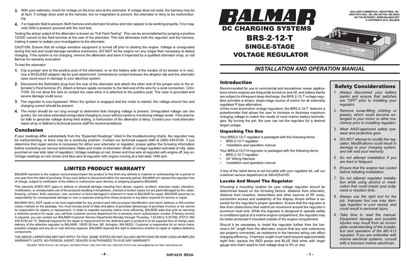
INTRODUCTION
Your Centerfielder provides a centralized
s ource of charging control for twin engine
applications where two alternators and two
regulators are us ed to charge a s ingle battery
bank. The Centerfield s ens es when only one
engine is running. When the s econd engine is
s tarted, the Centerfielder determines which
regulator's field current is dominant, and directs that field current to both alternators. This even distribution of
field current ens ures that both alternators deliver comparable percentages of their available capacities .
Outputs may vary bas ed on engine rpm' s , comparative alternator s ize, and dis tances from dominant regulator
to alternators . For bes t performance, regulators us ed s hould be identical.
In addition to its ability to equalize regulation to both alternators , the Centerfielder provides the as s urance
that both alternators will continue to s upply your batteries with charging amperage, s hould either s tarboard or
port s ide regulators fail.
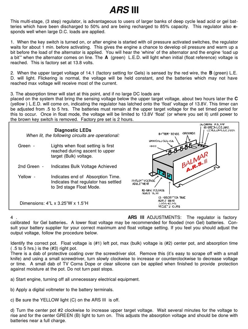
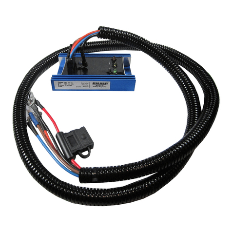
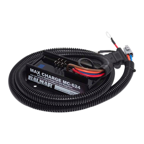
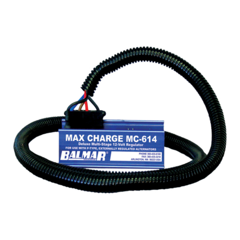
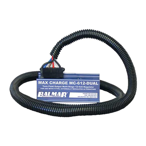
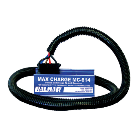
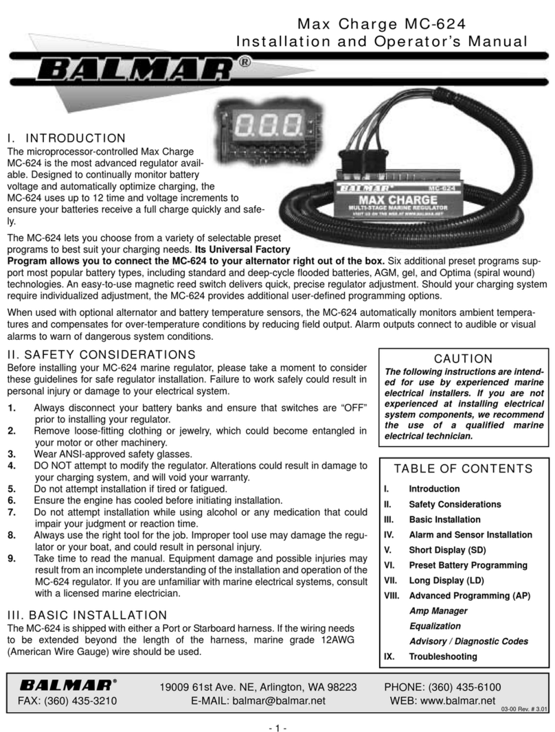
The Centerfielder is designed for use ONLY with Balmar MC-612 or MC624 regulators.
INSTALLATION
The Centerfielder is remarkably eas y to install. You will find, included with the Centerfielder, a collection of
s pade and wire tap connectors needed for ins tallation, as well as two fus ed 12 ga. replacement wires for the
regulator wiring harnes s es (s ee s tep 6). Field wires (12-gauge), ground wire (12-gauge) and ignition wires (14-
gauge) are us er s upplied. To ins tall:
1. Dis connect batteries or turn battery s witches to their " Off" pos i-
tions .
2. Ins tall the Centerfielder on a flat s urface (bulkhead) mid dis tance
between the two alternators .
3. Determine the dis tances required for wire runs between the
Centerfielder and the regulator wiring harnes s es as indicated on
the wiring illus tration on the revers e s ide of this s heet.
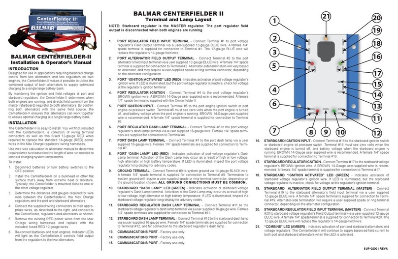
4. Connect the spade terminals as s hown, and plug appropriate wires
as illus trated in the diagram below.
5. Us ing the wire taps included, connect the us er s upplied wires to
the appropriate wires in the port and s tarboard s ide wiring har-
nes s es . Taps s hould be located within one inch (1 " ) of the regula-
tors .
6. Remove the existing red power wire from the regulator harness
and replace with the 12-ga. 15-amp fused red wire included with
the Centerfielder. Reconnect at the regulator and s ource of battery
voltage.
7. Re-connect batteries and start engines. The indicator LEDs will
light as the Centerfielder s elects the dominant regulator' s field cur-
rent.
Centerfielder
Ins tallation and Operator’s Manual
