manuals.online logo
Brands
  1. Home
  2. •
  3. Brands
  4. •
  5. Lumel
  6. •
  7. Controllers
  8. •
  9. Lumel RE60 User manual

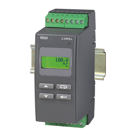
Lumel RE60 User manual

Other manuals for RE60

3

Other Lumel Controllers manuals

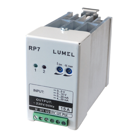
Lumel RP7 User manual

Lumel

Lumel RP7 User manual

Lumel RE60 User manual

Lumel

Lumel RE60 User manual

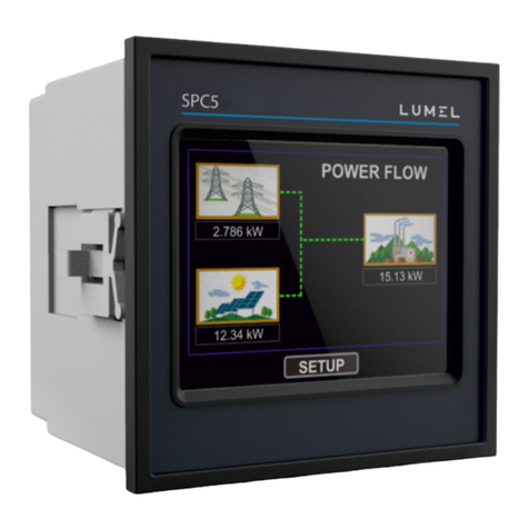
Lumel SPC5 User manual

Lumel

Lumel SPC5 User manual

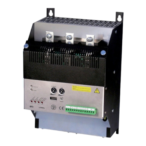
Lumel RP3 User manual

Lumel

Lumel RP3 User manual

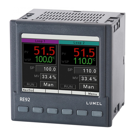
Lumel RE92 User manual

Lumel

Lumel RE92 User manual

Lumel re72 series User manual

Lumel

Lumel re72 series User manual

Lumel re72 series User manual

Lumel

Lumel re72 series User manual

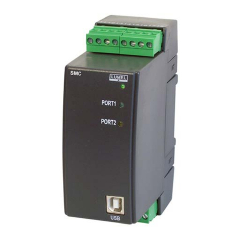
Lumel SMC series User manual

Lumel

Lumel SMC series User manual

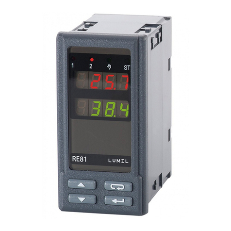
Lumel RE81 User manual

Lumel

Lumel RE81 User manual

Lumel re72 series User manual

Lumel

Lumel re72 series User manual

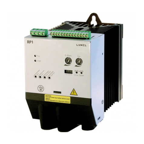
Lumel RP1 User manual

Lumel

Lumel RP1 User manual

Lumel RE15 User manual

Lumel

Lumel RE15 User manual

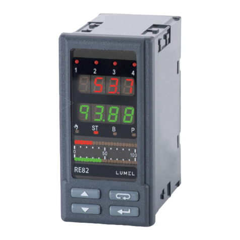
Lumel RE82 User manual

Lumel

Lumel RE82 User manual

Lumel re72 series User manual

Lumel

Lumel re72 series User manual

Lumel re72 series Instruction manual

Lumel

Lumel re72 series Instruction manual

Lumel RE70 User manual

Lumel

Lumel RE70 User manual

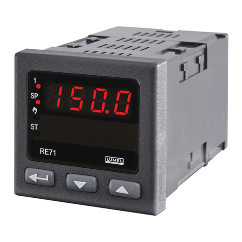
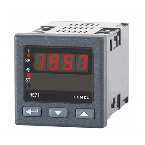
Lumel RE71 User manual

Lumel

Lumel RE71 User manual

Lumel RE92 User manual

Lumel

Lumel RE92 User manual

Lumel RE92 User manual

Lumel

Lumel RE92 User manual

Lumel re72 series User manual

Lumel

Lumel re72 series User manual

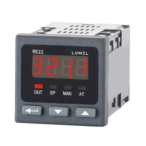
Lumel RE22 User manual

Lumel

Lumel RE22 User manual

Lumel RE92 User manual

Lumel

Lumel RE92 User manual

Lumel RE62 User manual

Lumel

Lumel RE62 User manual

Popular Controllers manuals by other brands

Sunricher SR-ZV9003T3-RGBW-US Installation

Sunricher

Sunricher SR-ZV9003T3-RGBW-US Installation

Ksenia intro Installation and configuration manual

Ksenia

Ksenia intro Installation and configuration manual

Inovance CAN200 Series manual

Inovance

Inovance CAN200 Series manual

Gauzy LC6 FLEX Controller Installation and operation guide

Gauzy

Gauzy LC6 FLEX Controller Installation and operation guide

Viking SLP-1 Technical practice

Viking

Viking SLP-1 Technical practice

CKD KBX-30E-U Series instruction manual

CKD

CKD KBX-30E-U Series instruction manual

Sharp Energy Sun Flux User manual & installation guide

Sharp Energy

Sharp Energy Sun Flux User manual & installation guide

Yamaha RCX40 user manual

Yamaha

Yamaha RCX40 user manual

AB Quality PowerFlex 400 Frames D-H Service bulletin

AB Quality

AB Quality PowerFlex 400 Frames D-H Service bulletin

Yamaha MJC8 owner's manual

Yamaha

Yamaha MJC8 owner's manual

AL-KO ATC operating instructions

AL-KO

AL-KO ATC operating instructions

Savant SmartControl 2 Deployment guide

Savant

Savant SmartControl 2 Deployment guide

GameSir T3S user manual

GameSir

GameSir T3S user manual

Kostal inveor operating manual

Kostal

Kostal inveor operating manual

Emerson Yarway 20-55 Operating and safety instructions

Emerson

Emerson Yarway 20-55 Operating and safety instructions

CoCo ACM-LV24 Quick installation guide

CoCo

CoCo ACM-LV24 Quick installation guide

Brooks SLA5810/20 Installation and operation manual

Brooks

Brooks SLA5810/20 Installation and operation manual

SIGMA TEK SR 011 Technical manual

SIGMA TEK

SIGMA TEK SR 011 Technical manual

manuals.online logo
manuals.online logoBrands
  • About & Mission
  • Contact us
  • Privacy Policy
  • Terms and Conditions

Copyright 2025 Manuals.Online. All Rights Reserved.

1
TEMPERATURE
CONTROLLER
MOUNTED ON A 35 mm RAIL
RE60 TYPE
USERS MANUAL
2
3
Contents
1. Application ................................................................................ 5
2. Controller set ............................................................................ 5
3. Preparing the controller for opereation .................................... 6
3.1. Security .............................................................................. 6
3.2. Controller installation ......................................................... 6
3.3. Electrical connections ....................................................... 7
3.4. Installation recommendations ........................................... 9
4. Starting to work ...................................................................... 10
5. Programming controller parameters ...................................... 11
5.1. Diagram of the controller menu ....................................... 11
5.2. List of controller parameters............................................ 13
6. Control .................................................................................... 16
6.1. ON-OFF control ............................................................... 16
6.2. PID control ....................................................................... 17
7. Alarms ..................................................................................... 20
8. Auxiliary functions .................................................................. 21
8.1. Displaying the control signal ........................................... 21
8.2. Controller behaviour after sensor damage ..................... 21
8.3. Factory settings ............................................................... 21
9. Error signalling ........................................................................ 22
10. Technical data ....................................................................... 23
11. Ordering codes ..................................................................... 26
12. Maintenance and warranty ................................................... 26
4
5
1. APPLICATION
The RE60 controller controls the temperature in objects through
turning on and off the electrical controlling device according to
the defined setting by the controller. It cooperates directly with RTD
and TC.
It is destined for the temperature control in telecommunication
cabinets in food and drying industries and everywhere, where there
is the necessity to stabilize the temperature changes.
The controller has one output destined for the control and two alarm
outputs.
2. ZESTAW REGULATORA
Controller - 1 pc
User’s
manual
User’s
manual
Warranty
card
Warranty
card
Plug - 2 pcs Users manual - 1 pc
Warranty card - 1 pc
Quick start card - 1 pc
When unpacking the controller, please check whether the type
and version code on the data plate correspond to the order.
6
3. PREPARING THE CONTROLLER FOR OPERATION
When unpacking the controller, please check whether the type
and version code on the data plate correspond to the order.
3.1. Security
The RE60 controller fulfils requirements concerning the security of
electrical measuring automation instruments acc. to EN 61010-1
standard requirements concerning the resistance against electro-
magnetic noise acc. to EN 61000-6-2 standard and emission
of electromagnetic noise occurring in the industrial environment
acc. to EN 61000-6-4 standard.
BASIC REQUIREMENTS, SAFETY INFORMATION
Symbols located in this service manual mean:
WARNING!
Warning of potential, hazardous situations.
Especially important. One must acquaint with this
before connecting the instrument.
The non-observance of notices marked by these
symbols can occasion severe injuries of the personnel
and the damage of the instrument !
CAUTION!
Designates a general useful note. If you observe it,
handling of the controller is made easier.
One must take note of this, when the instrument
is working inconsistently to the expectations.
Possible consequences if disregarded !
In the security scope the RE60 controller meets the requirements
of the EN 61010 -1 standard.
?
7
Remarks concerning the operator safety:
1. General
- The instrument is destined to be mounted on a 35 mm rail
- Non-authorized removal of the required housing, inappropriate
use, incorrect installation or operation create the risk of injury to
personnel or damage to equipment. For more detailed information,
please study the present users manual.
- All operations concerning transport, installation, and commissioning
as well as maintenance must be carried out by qualified, skilled
personnel and national regulations for the prevention of accidents
must be observed.
- According to this basic safety information, qualified,skilled
personnel are personswho are familiar with the installation,
assembly, commissioning, and operation of the product and who
have qualifications necessary for their occupation.
2. Transport, storage
Please observe the notes on transport, storage and appropriate
handling.
Observe the climatic conditions given in technical data.
3. Installation
- The controller must be installed according to the regulation
and instructions given in this users manual
- Ensure proper handling and avoid mechanical stress.
- Do not bend any components and do not change any insulation
distances.
- Do not touch any electronic components and contacts.
- Instruments may content electrostatically sensitive components,
which can easily be damaged by inappropriate handling.
Do not damage or destroy any electrical components since this
might endanger your heath!
?
8
4. Electrical connection
- Before switching the instrument on, one must check the correctness
of connection to the network.
- In case of the protection terminal connection with a separate lead
one must remember to connect it before the connection of the
instrument to the mains.
- When working on live instruments, the applicable national regulations
for the prevention of accidents must be observed.
- The electrical installation must be carried out according to the
appropriate regulations (cable cross-sections, fuses, PE connection).
Additional information can be obtained from the users manual.
- The documentation contains information about installation in
compliance with EMC (shielding, grounding, filters and cables).
These notes must be observed for all CE-marked products.
- The manufacturer of the measuring system or installed devices is
responsible for the compliance with the required limit values
demanded by the EMC legislation.
5. Operation
- Measuring systems including RE60 controllers must be equipped
with protection devices according to the corresponding standard
and regulations for prevention of accidents.
- After the instrument has been disconnected from the supply
voltage, live components and power connections must not be
touched immediately because capacitors can be charged.
- The housing must be closed during operation.
6. Maintenance and servicing.
- Please observe the manufacturers documentation and read all
product-specific safety and application notes in this users manual.
- Before taking the meter housing out, one must turn the supply off.
- The removal of the instrument housing during the warranty
contract period may cause its cancellation.
When unpacking the controller, please check whether the type
and version code on the data plate correspond to the order.
9
3.2. Controller installation
Fix the controller on the 35 mm rail acc. to EN 60715.
The controller housing is made of a self-extinguishing plastics.
Dimensions of the controller and the fixing way is presented on the
fig.1
Fig.1. Dimensions and fixing way of the controller
RE60
120
45
35
100
120,7
93
41
lock
When unpacking the controller, please check whether the type
and version code on the data plate correspond to the order.
?
10
3.3. Electrical connections
Carry out electrical connections to the terminal strips and next insert
strips into controller sockets.
Fig.2. View of controller connection strips
Input
signals
SupplyWY1 A1 A2
1
910 11 12 13 14 15 16
2345678
?