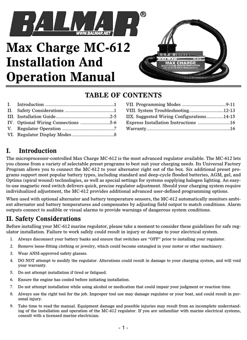
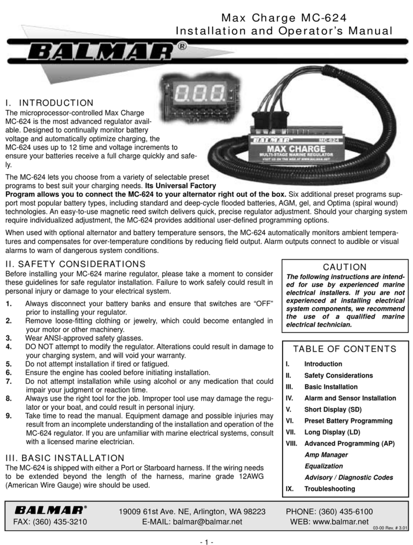
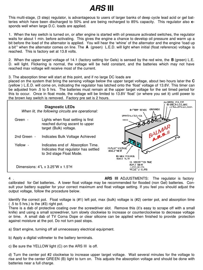
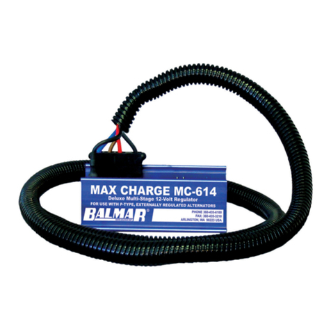
Balmar 96 Series User manual

1
www.balmar.net / Customer Service: +1 (360) 435-6100 x1 / Technical Support: +1 (360) 435-6100 x3
Tech Service is available Monday - Friday (8:30am - 7:30pm EST)
INSTALLATION AND OPERATION MANUAL
INTRODUCTION
Safety Considerations
1. Always disconnect your battery banks
and ensure that switches are “OFF” prior
to installing your regulator.
2. Remove loose-tting clothing or jewelry,
which could become entangled in
your motor or other machinery prior to
installing regulator and alternator.
3. Wear ANSI-approved safety eye-wear
and protective gear.
4. DO NOT attempt to modify the regulator
or alternator. Modications could result
in damage to your charging system, and
will void your warranty.
5. DO NOT attempt installation if you are
tired or fatigued.
6. Ensure that the engine has cooled before
initiating installation.
7. DO NOT attempt regulator installation
while using alcohol or medication that
could impair your judgment or reaction
time.
8. Always use the right tool for the job.
Improper tool use may damage regulator
or your vessel, and could result in
personal injury.
9. Take time to read the manual. Equipment
damage and possible injuries may result
from an incomplete understanding of the
installation and operation of the MC-620
regulator and 96-Series alternators. If
you are unfamiliar with marine electrical
systems, consult with a licensed marine
electrician.
96-SERIES ALTERNATOR
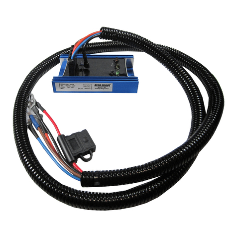
MAX CHARGE MC-620
MULTI-STAGE
VOLTAGE REGULATOR
©2020 Balmar LLC SUP-0276 REV.A 3/30/2020
Introduction 1 Regulator Progamming 12
Safety Considerations 1 Basic Programming 12
Alternator Installation 2 Belt Load Manager 11
Alternator to Battery Fusing 3 LiFePO4 Recommendtions 12
Alt. to Battery Capacity Ratio 3 Programming Flow Chart 13
96-Series Alternator Wiring 4 Belt Load Manager 15
MC-620 Regulator Installation 5 Short and Long Display 15
Unpacking the Box 5 Alternator Advisory 15
Locating and Mouting the Reg 6 Adv. Programming 16
Basic Wiring Installation 7 Battery Equalization 17
Installation By Wire 7-8 Default Program Settings 18
Initial Pre-Flight Test and Start 9 Add’l. Regulator Features 18
Regulator Operation 10 Troubleshooting 19-20
Regulator Display Modes 11 Warranty 21
Table of Contents

2
www.balmar.net / Customer Service: +1 (360) 435-6100 x1 / Technical Support: +1 (360) 435-6100 x3
Tech Service is available Monday - Friday (8:30am - 7:30pm EST)
a qualied marine electrical technician.
The
NOTE:
NOTE:
ALTERNATOR INSTALLATION CONSIDERATIONS

3
www.balmar.net / Customer Service: +1 (360) 435-6100 x1 / Technical Support: +1 (360) 435-6100 x3
Tech Service is available Monday - Friday (8:30am - 7:30pm EST)
ALTERNATOR TO BATTERY FUSING
ALTERNATOR OUTPUT-TO-BATTERY CAPACITY RATIO
4

4
www.balmar.net / Customer Service: +1 (360) 435-6100 x1 / Technical Support: +1 (360) 435-6100 x3
Tech Service is available Monday - Friday (8:30am - 7:30pm EST)
B+
B-
96-SERIES ALTERNATOR WIRING
1. Positive Output Terminal
2. Auxiliary Ground Post
3. External Field Wire (BLUE)
4. Stator Output Wire (WHITE)
5. Temp Sensor (Not Shown)
Unsupported cables may damage the positive or negative terminals, resulting in damage to alternator, regulator and
wiring. Ensure that cables are adequately supported to supply strain relief.
3
4
1
2

5
www.balmar.net / Customer Service: +1 (360) 435-6100 x1 / Technical Support: +1 (360) 435-6100 x3
Tech Service is available Monday - Friday (8:30am - 7:30pm EST)
MC-620 REGULATOR INSTALLATION
UNPACKING THE BOX
•
•
•
•
•
LOCATE AND MOUNT THE REGULATOR
BASIC WIRING INSTALLATION
Connecting the 12V Power lead from the regulator to a 48V battery bank or the B+ Terminal of the
alternator will destroy the regulator. This is not covered under warranty. Only connect the 12V
power lead to a 12V battery, typically the engine starting battery.

6
www.balmar.net / Customer Service: +1 (360) 435-6100 x1 / Technical Support: +1 (360) 435-6100 x3
Tech Service is available Monday - Friday (8:30am - 7:30pm EST)
1. GROUND INPUT
2. POWER INPUT - 12V ONLY!!!!
3. IGNITION INPUT - 12V ONLY!!!
4. FIELD OUTPUT
5. ALT. TEMP. (-)
6. ALT. TEMP. (+)
7. BAT. TEMP. #1 (-)
8. BAT. TEMP. #1 (+)
9. 48V BATTERY VOLTAGE SENSE
10. DATA TX
11. DATA RX
12. STATOR IN
13. TACHOMETER OUT
14. BAT. #2 TEMP. (-)
15. BAT. #2 TEMP. (+)
16. AUX. #1 LAMP
17. DASH LAMP
MC-620 Regulator Terminal Layout
Magnetic
Reed Switch
17
16
1514
13
12
11
10
9
8
7
65
1
2
3
4
1. Ground Input
2. 12V Power Input
3. 12V Ignition Input
4. Field Output
5. Alt. Temp.(-)
6. Alt. Temp.(+)
7. Bat. #1 Temp.(-)
8. Bat. #1 Temp.(+)
9. 48V Battery Voltage Sensor
10. Data TX
11. Data RX
12. Stator In
13. Tach. Out
14. Bat. #2 Temp. (-)
15. Bat. #2 Temp. (+)
16. Aux. #1 Lamp
17. Dash Lamp
48V
B-
B+
START
12V
B-
L
WARNING: DO NOT
MAY RESULT IN FIRE

7
www.balmar.net / Customer Service: +1 (360) 435-6100 x1 / Technical Support: +1 (360) 435-6100 x3
Tech Service is available Monday - Friday (8:30am - 7:30pm EST)
INSTALLATION BY WIRE
NOTE: Must install wires listed on this page for regulator to operate.
INSTALL BLACK GROUND WIRE
INSTALL RED POWER WIRE
INSTALL BROWN IGNITION WIRE
INSTALL BLUE FIELD WIRE
INSTALL ALTERNATOR TEMPERATURE SENSOR
INSTALL POSITIVE BATTERY SENSE WIRE (48V)
The included voltage sense wire length is designed to sense at the B+ terminal of the al-The included voltage sense wire length is designed to sense at the B+ terminal of the al-
ternator. For the most accurate voltage sensing and better charging performance, considerternator. For the most accurate voltage sensing and better charging performance, consider
extending the voltage sense wire to run directly between the regulator and the 48V batteryextending the voltage sense wire to run directly between the regulator and the 48V battery
bank. This method is also used if using a battery isolator, or sensing at another location such as a battery switch (Anywherebank. This method is also used if using a battery isolator, or sensing at another location such as a battery switch (Anywhere
other than the alternator.)other than the alternator.)
Crimp the
Magnetic
Reed Switch
17
16
1514
13
12
11
10
9
8
7
65
1
2
3
4
Magnetic
Reed Switch
17
16
1514
13
12
11
10
9
8
7
65
1
2
3
4

8
www.balmar.net / Customer Service: +1 (360) 435-6100 x1 / Technical Support: +1 (360) 435-6100 x3
Tech Service is available Monday - Friday (8:30am - 7:30pm EST)
CAUTION: Reversing the polarity of the terminal connections on any of the alternator or battery
temperature sensors can result in invalid sensing and potential damage to alternators, regulator and/or
batteries.
INSTALL BATTERY #1 TEMPERATURE SENSOR
essential that the terminals
INSTALL WHITE STATOR-IN AND TACH-OUT WIRES
NOTE: Do not attempt to use the White Stator Out to drive a tachometer
unless you have veried that it can be safely driven from a 48V alternator
output. Consult the Tachometer Manufacturer if you are unsure.
INSTALL BATTERY #2 TEMPERATURE SENSOR
are
DATA TX AND DATA RX
are only for factory use.
Magnetic
Reed Switch
17
16
1514
13
12
11
10
9
8
7
65

1
2
3
4

9
www.balmar.net / Customer Service: +1 (360) 435-6100 x1 / Technical Support: +1 (360) 435-6100 x3
Tech Service is available Monday - Friday (8:30am - 7:30pm EST)
INSTALL AUX. 1 LAMP
INSTALL DASH LAMP
INITIAL PRE-FLIGHT TEST AND START-UP
TEST #1: Engine/Ignition OFF
•
•
•
•
TEST #2: Engine not Running/Ignition ON (Wait 2 minutes)
•
•
•
•
To Aux 1
or Dash Lamp
To Battery +
Lamp Connections
o
o
360-435-6100360-435-3210
www.balmar.net

10
www.balmar.net / Customer Service: +1 (360) 435-6100 x1 / Technical Support: +1 (360) 435-6100 x3
Tech Service is available Monday - Friday (8:30am - 7:30pm EST)
REGULATOR OPERATION
1. Start Delay.
2. Soft Ramp.
3. Bulk Charge.
4. Calculated Bulk Charge.
5. Ramp to Absorption.
6. Absorption Charge.
7. Calculated Absorption Charge.
8. Ramp to Float.
9. Float Charge.
10.Calculated Float Charge.
1 sec. 60 sec. 18 min. Up to 6 hrs. 18 min. Up to 6 hrs. 18 min. Up to 6 hrs. 18 min. Up to 6 hrs. 18 min. Up to 6 hrs.
START DELAY
SOFT RAMP
BULK
CALCULATEDBULK
RAMP TO ABSORPTION
ABSORPTION
CALCULATEDABSORPTION
RAMP TO FLOAT
FLOAT
CALCULATEDFLOAT
RAMP TO ABSORPTION
CALCULATEDABSORPTION
RAMP TO FLOAT
FLOAT
CALCULATEDFLOAT
ABSORPTION

11
www.balmar.net / Customer Service: +1 (360) 435-6100 x1 / Technical Support: +1 (360) 435-6100 x3
Tech Service is available Monday - Friday (8:30am - 7:30pm EST)
BAL
620
UFP
b-0
-b-
bv
Cv
b1
AL
b2
E10 BATTERY #1 SENSOR
CABLE SHORTED
E11 BATTERY #1 TEMP. SENSOR
CABLE OPEN OR NOT FOUND
E12 BATTERY #2 TEMP. SENSOR
CABLE SHORTED
E13 BATTERY #2 TEMP. SENSOR
CABLE OPEN OR NOT FOUND
E14 ALTERNATOR #1 TEMP.
SENSOR CABLE SHORTED
E15 ALTERNATOR #1 TEMP.
SENSOR CABLE OPEN OR NOT
FOUND
E20 BATTERY #1 TOO HOT OVER
55°C. FACTORY DEFAULT
E21 BATTERY #2 TOO HOT. OVER
55°C. FACTORY DEFAULT
E22 ALTERNATOR TOO HOT.
OVER 107°C
E24 VOLTAGE REGULATOR TOO
HOT. OVER 90°C
E25 BATTERY #1 TOO COLD
E33 BATTERY SENSE DIS-
CONECTED
E41 FIELD VOLTAGE TOO HIGH
E42 STATOR VOLTAGE TOO
HIGH
E51 SMALL ENGINE MODE IS IN
OPERATION
FE
r4.1
SP
SLP
Hr.
FbA
FFL
E
REGULATOR DISPLAY MODES - SHORT DISPLAY / LONG DISPLAY

12
www.balmar.net / Customer Service: +1 (360) 435-6100 x1 / Technical Support: +1 (360) 435-6100 x3
Tech Service is available Monday - Friday (8:30am - 7:30pm EST)
Pro INDICATES ENTRY INTO BASIC
PROGRAMMING MODE
bA INDICATES ENTRY INTO
BATTERY TYPE PROGRAM MODE
UFP INDICATES FACTORY DEFAULT
UNIVERSAL FACTORY MODE
Fdc INDICATES PROGRAM FOR
DEEP CYCLE FLOODED BATTERIES
gEL INDICATES PROGRAM FOR
DEEP CYCLE GEL BATTERIES
AgL INDICATES PROGRAM FOR
ABSORBED GLASS MAT BATTERIES
OPS INDICATES PROGRAM FOR
SPIRAL WOUND (OPTIMA)
FSb INDICATES PROGRAM FOR
STD. FLOODED BATTERIES
HAL INDICATES PROGRAM
FOR HALOGEN SYSTEMS
LFP INDICATES PROGRAM
FOR LiFePO4
REGULATOR PROGRAMMING MODES
USING THE MAGNETIC REED SWITCH
activate
TOUCH/RELEASE - Indicates the action of contacting and immediately removing the magnet from the reed switch
TOUCH/HOLD - Indicates the action of contacting and holding the magnet to the reed switch
BASIC PROGRAMMING
PROGRAMMING FOR BATTERY TYPE
4

13
www.balmar.net / Customer Service: +1 (360) 435-6100 x1 / Technical Support: +1 (360) 435-6100 x3
Tech Service is available Monday - Friday (8:30am - 7:30pm EST)
LFP/LiFePO4RECOMMENDATIONS
4
4

14
www.balmar.net / Customer Service: +1 (360) 435-6100 x1 / Technical Support: +1 (360) 435-6100 x3
Tech Service is available Monday - Friday (8:30am - 7:30pm EST)
REGULATOR PROGRAMMING FLOW CHART
“PRO”
Entered
Program
Mode
“bA”
Battery
Type
“dSP”
Display
Mode
“bdL”
Alternator
Failure
Advisory
“---”
Advanced
Programming
“Password”
Entry
4
“bEL”
Belt Load
Manager
Max
Max
Max
Max
Max
Max
Max
Max
Max
3 Times?
Max
Compensation Limit
“bv”
Bulk Voltage
“A1C”
Fixed Absorb Time
“Fv”
Float Voltage
“F1C”
Fixed Float Time
“ALL”
Low Voltage Limit

15
www.balmar.net / Customer Service: +1 (360) 435-6100 x1 / Technical Support: +1 (360) 435-6100 x3
Tech Service is available Monday - Friday (8:30am - 7:30pm EST)
PROGRAMMING THE BELT LOAD MANAGER
the
activate
bEL INDICATES ENTRY INTO
BELT LOAD MANAGER MODE
b-0 INDICATES BLM OFF.
b-1 INDICATES BLM SETTING #1.
FIELD REDUCTION 5%.
b-2 INDICATES BLM SETTING #2.
FIELD REDUCTION 10%.
b-3 INDICATES BLM SETTING #3.
FIELD REDUCTION 15%.
b-4 INDICATES BLM SETTING #4.
FIELD REDUCTION 20%.
b-5 INDICATES BLM SETTING #5.
FIELD REDUCTION 25%.
b-6 INDICATES BLM SETTING #6.
FIELD REDUCTION 30%
b-7 INDICATES BLM SETTING #7.
FIELD REDUCTION 35%.
b-8 INDICATES BLM SETTING #8.
FIELD REDUCTION 40%
b-9 INDICATES BLM SETTING #9.
FIELD REDUCTION 45%
PROGRAMMING FOR SHORT OR LONG DISPLAY MODE
change your selection, or wait until the regulator cycles to the next programming mode.
dSP INDICATES ENTRY INTO SHORT
OR LONG DISPLAY MODE
Sd INDICATES SHORT
DISPLAY MODE
Ld INDICATES LONG
DISPLAY MODE
PROGRAMMING FOR ALTERNATOR FAILURE ADVISORY MODE (BDL)
bdL INDICATES ENTRY INTO
ALTERNATOR FAILURE
ADVISORY MODE
OFF STATOR OUTPUT
MONITORING OFF
ON STATOR OUTPUT
MONITORING ON

16
www.balmar.net / Customer Service: +1 (360) 435-6100 x1 / Technical Support: +1 (360) 435-6100 x3
Tech Service is available Monday - Friday (8:30am - 7:30pm EST)
ADVANCED PROGRAMMING MODES
ACCESSING THE ADVANCED PROGRAMMING MODE
The
Pro INDICATES ENTRY INTO
PROGRAM MODE
bA INDICATES SELECTION
MODE FOR BATTERY TYPE
bEL INDICATES SELECTION
MODE FOR BELT LOAD
MANAGER
dSP INDICATES SELECTION MODE
FOR SHORT/LONG DISPLAY
bdL INDICATES ALTERNATOR
FAILURE ADVISORY (BDL)
--- INDICATES ENTRY INTO
PASSWORD MODE FOR AP MODE
AP1 INDICATES ENTRY INTO
PASSWORD MODE FOR AP MODE
AP5 INDICATES PASSWORD FOR
ADVANCED PROGRAM MODE
PrA INDICATES ENTRY INTO THE
ADVANCED PROGRAM MODE
MAKING ADVANCED PROGRAMMING ADJUSTMENTS
(PrA) Advanced Program Mode.
(dLc) Start Delay.
(AHL) High Voltage Limit.
(CL) Compensation Limit.
(bv) Bulk Voltage.
(b1c) Bulk Time.
(Av) Absorption Voltage.
(A1c) Absorption Time.
(Fv) Float Voltage.

17
www.balmar.net / Customer Service: +1 (360) 435-6100 x1 / Technical Support: +1 (360) 435-6100 x3
Tech Service is available Monday - Friday (8:30am - 7:30pm EST)
BATTERY EQUALIZATION
WARNING: EQUALIZATION IS A MANUAL PROCESS WITH POTENTIAL DANGERS.
DO NOT LEAVE SYSTEM UNATTENDED.
(F1c) Float Time.
(ALL) Low Voltage Limit.
(FbA) Field Threshold - Bulk and Absorption.
(FFL) Field Threshold - Float to Absorption.
(AL1) Alternator Temperature Threshold. Controls the
(b1L) Battery Temperature Threshold. Controls the
(SLP) Slope Voltage Correction.

18
www.balmar.net / Customer Service: +1 (360) 435-6100 x1 / Technical Support: +1 (360) 435-6100 x3
Tech Service is available Monday - Friday (8:30am - 7:30pm EST)
ADDITIONAL REGULATOR FEATURES
SMALL ENGINE MODE
terminals
DASH LAMP
visual
•
•
•
•
• 4
•
•
AUX #1 LAMP
or
•
•
Default Program Settings By Battery Type
UFP Fdc gEL AgL OPS FsB HAL LFP

19
www.balmar.net / Customer Service: +1 (360) 435-6100 x1 / Technical Support: +1 (360) 435-6100 x3
Tech Service is available Monday - Friday (8:30am - 7:30pm EST)
SYSTEM TROUBLESHOOTING
REGULATOR TROUBLESHOOTING
VOLTAGE REGULATOR TESTING
•
•
•
•
•
•
•
•
•
•
•
•

20
www.balmar.net / Customer Service: +1 (360) 435-6100 x1 / Technical Support: +1 (360) 435-6100 x3
Tech Service is available Monday - Friday (8:30am - 7:30pm EST)
ALTERNATOR TESTING
a
CONCLUSION
This manual suits for next models
3
Table of contents
Other Balmar Controllers manuals

Balmar
Balmar ARS-5 User manual

Balmar
Balmar Max Charge MC-614-H User manual

Balmar
Balmar ARS-5-H User manual

Balmar
Balmar Max Charge MC-624 Setup guide

Balmar
Balmar BRS-2-12-T User manual

Balmar
Balmar Centerfielder Setup guide

Balmar
Balmar BRS-2T-24 User manual

Balmar
Balmar Max Charge MC-618 User manual

Balmar
Balmar MAX CHARGE MC-614 User manual

Balmar
Balmar MAX CHARGE MC-612-DUAL User manual