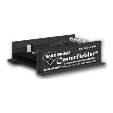
BALMAR CENTERFIELDER-II
Installation & Operator’s Manual
INTRODUCTION
Designed for use in applications requiring balanced charge
control from two alternators and two regulators on twin
engines, the Centerfielder-II makes it possible to utilize the
combined output of both alternators to supply optimized
charging to a single large battery bank.
By monitoring the ignition and field voltages at port and
starboard regulators, the Centerfielder-II determines when
both engines are running, and directs field current from the
master (starboard) regulator to both alternators. By control-
ling both alternators with the same field source, the
Centerfielder-II ensures that alternators can work together
to ensure optimal charging at a single large battery bank.
INSTALLATION
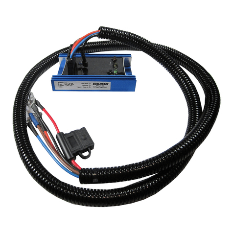
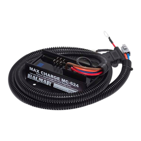
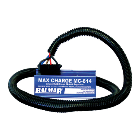
The Centerfielder-II is easy to install. You will find, included
with the Centerfielder-II, a collection of wiring terminal
connectors as well as two fused 12-gauge RED wires
required to replace the standard 14-gauge (RED) power
wires in the Max Charge regulators’ wiring harnesses.
Use wire size calculation in alternator manual to determine
required wire size based on the length of wire run needed to
connect charging system components.
To install:
1. Disconnect batteries or turn battery switches to the
OFF position.
2. Install the Centerfielder-II on a bulkhead or other flat
surface that’s away from extreme heat or moisture.
Typically, the Centerfielder is mounted close to one or
the other voltage regulator.
3. Determine the distances and gauges required for wire
runs between the Centerfielder-II, the Max Charge
regulators and the port and starboard alternators.
4. Connect the supplied wiring connectors to their appro-
priate wires, as described to the right, and connect to
the Centerfielder, regulators and alternators as shown.
5. Remove the existing RED power wires from the Max
Charge wiring harnesses and replace with the
included, fused RED 12-gauge wires.
6. Re-connect batteries and start engines. Indicator LEDs
will light as the Centerfielder-II controls field output
from the regulators to the two alternators.
1
2
3
5
4
6
7 8 9 10 12
11
17
13
14
15
16
18
19
20
21
BALMAR CENTERFIELDER II
Terminal and Lamp Layout
NOTE: Starboard regulator is the MASTER regulator. The port regulator field
output is disconnected when both engines are running
1. PORT REGULATOR FIELD INPUT TERMINAL - Connect Terminal #1 to port voltage
regulator’s Field Output terminal via a user-supplied 12-gauge BLUE wire. A female 1/4”
spade terminal is supplied for connection to Terminal #1. The 12-gauge BLUE wire will
replace the regulator’s 14-gauge field wire.
2. PORT ALTERNATOR FIELD OUTPUT TERMINAL - Connect Terminal #2 to the port
alternator’s field input terminal via a user supplied 12-gauge BLUE wire. A female 1/4” spade
terminal is supplied for connection to Terminal #2. Alternator-side termination will vary based
on alternator, and may require a user-supplied spade or ring terminal connector, depending
on the alternator configuration.
3. PORT “IGNITION ACTIVATED” LED (RED) - Indicates activation of port voltage regulator’s
ignition wire. If LED is illuminated, but the port voltage regulator is inactive, check for voltage
at the regulator’s ignition terminal.
4. PORT REGULATOR IGNITION - Connect Terminal #4 to the port voltage regulator’s
BROWN ignition wire. A BROWN 14-Gauge user-supplied wire is recommended. A female
1/4” spade terminal is supplied with the Centerfielder II.
5. PORT IGNITION INPUT - Connect Terminal #5 to the port engine ignition switch or port
engine oil pressure switch. Terminal #5 must see zero volts when the port engine is turned
off, and battery voltage when the port engine is running. BROWN 14-Gauge user-supplied
wire is recommended. A female 1/4” spade terminal is supplied for connection to Terminal
#5.
6. PORT REGULATOR DASH LAMP TERMINAL - Connect Terminal #6 to the port voltage
regulator’s dash lamp terminal via a user supplied 16-gauge wire. Female 1/4” spade termi-
nals are supplied for connection to Terminal #6.
7. PORT DASH LAMP TERMINAL - Connect Terminal #7 to the port dash lamp via a user
supplied 16-gauge wire. Female 1/4” spade terminals are supplied for connection to Termi-
nal #7.
8. PORT “DASH LAMP” LED (RED) - Indicates activation of port voltage regulator’s Dash
Lamp terminal. Activation of the Dash Lamp may occur as a result of high or low voltage,
high alternator or high battery temperature. If LED is illuminated, inspect the port voltage
regulator long display for advisory codes.
9. GROUND TERMINAL - Connect Terminal #9 to system ground via 14-gauge BLACK wire.
A female 1/4” spade terminal is supplied for connection to Terminal #9. Termination to
system ground will require a user-suppled spade or ring terminal connector, depending on
the ground location chosen. ALL GROUND CONNECTIONS MUST BE COMMON.
10. STARBOARD “DASH LAMP” LED (GREEN) - Indicates activation of starboard voltage
regulator’s Dash Lamp terminal. Activation of the Dash Lamp may occur as a result of high
or low voltage, high alternator or high battery temperature. If LED is illuminated, inspect the
starboard voltage regulator long display for advisory codes.
11. STARBOARD REGULATOR DASH LAMP TERMINAL - Connect Terminal #11 to the
starboard voltage regulator’s dash lamp terminal via a user supplied 16-gauge wire. Female
1/4” spade terminals are supplied for connection to Terminal #11.
12. STARBOARD DASH LAMP TERMINAL - Connect Terminal #12 to the starboard dash lamp
via a user supplied 16-gauge wire. Female 1/4” spade terminals are supplied for connection
to Terminal #12, and for connection to the starboard regulator’s dash lamp.
13. COMMUNICATIONS PORT - Factory use only.
14. COMMUNICATIONS PORT - Factory use only.
15. COMMUNICATIONS PORT - Factory use only.
16. STARBOARD IGNITION INPUT - Connect Terminal #16 to the starboard ignition switch
or starboard engine oil pressure switch. Terminal #16 must see zero volts when the
starboard engine is turned off, and battery voltage when the starboard engine is
running. BROWN 14-Gauge user-supplied wire is recommended. A female 1/4” spade
terminal is supplied for connection to Terminal #16.
17. STARBOARD REGULATOR IGNITION - Connect Terminal #17 to the starboard voltage
regulator’s BROWN ignition wire. A BROWN 14-Gauge user-supplied wire is recom-
mended. A female 1/4” spade terminal is supplied for connection to Terminal #17.
18. STARBOARD “IGNITION ACTIVATED” LED (GREEN) - Indicates activation of
starboard voltage regulator’s ignition wire. If LED is illuminated, but the starboard
voltage regulator is inactive, check for voltage at the regulator’s ignition terminal.
19. STARBOARD ALTERNATOR FIELD OUTPUT TERMINAL (MASTER) - Connect
Terminal #19 to the starboard alternator’s field input terminal via a user supplied
12-gauge BLUE wire. A female 1/4” spade terminal is supplied for connection to Termi-
nal #19. Alternator-side termination will require a user-supplied spade or ring terminal
connector, depending on the alternator configuration.
20. STARBOARD REGULATOR FIELD INPUT TERMINAL (MASTER) - Connect Terminal
#20 to starboard voltage regulator’s Field Output terminal via a user-supplied 12-gauge
BLUE wire. A female 1/4” spade terminal is supplied for connection to Terminal #20. The
12-gauge BLUE wire will replace the regulator’s 14-gauge field wire.
21. “COMBINE” LED (AMBER) - Indicates activation of port and starboard alternators and
voltage regulators. The Centerfielder-II will continue to supply balanced field current to
both port and starboard alternators when the LED is activated.
SUP-0200 | REVA
