Bandit
8
Copyright 3/17
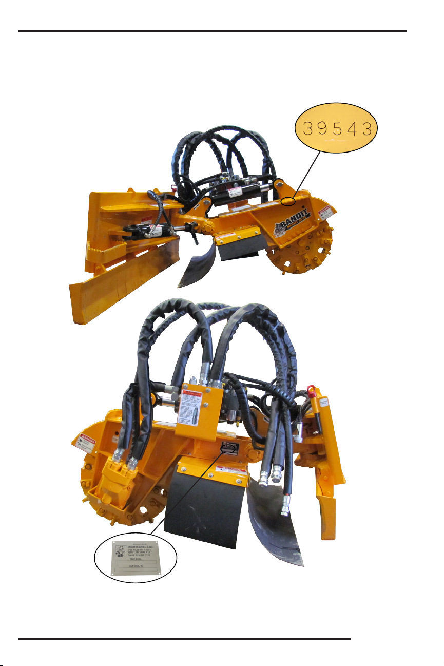
MODEL SA-25
Do Not enter or exit the operator’s cab unless:
the cutter head has come to a complete stop, the
cutter head is setting on the ground, and the ignition
key is in the operator’s possession.
DANGER
!
SAFETY PROCEDURES
It is very important after you have operated a new
machine for approximately an hour to shut down the
machine and recheck all nuts and bolts. It is normal
for nuts and bolts to loosen once on a new piece of
machinery. If you tighten them now, there is a good
possibility they won’t loosen again. Certain nuts and
bolts should be checked periodically such as cutter
teeth bolts, etc. for torque and t.
Most of the nuts used on the Bandit Grinder are
self locking. After a nut or bolt has been removed
ve times, it should be replaced to ensure proper
tightness. This is especially critical on the cutter tooth
bolts!
After the engine is started, let the grinder tooth
turn at the lowest RPM’s possible. Listen for any
type of noise that is foreign. Any steel on steel noise
is foreign. If you hear a noise, stop the engine, nd
the problem and x it.
It is very important after you have operated a new
machine for approximately an hour to shut down the
machine and recheck all hydraulic ttings. Retighten
as needed.
DO NOT GO NEAR HYDRAULIC LEAKS! High
pressure oil easily punctures skin causing serious
injury, gangrene, or death. Avoid burns from uid.
Hot uid under pressure can cause severe burns.
DO NOT use ngers or skin to check for leaks. Lower
load or relieve hydraulic pressure before loosening
ttings. Relieve all pressure in the system before
disconnecting the lines, hoses, or performing other
work. Use a piece of cardboard to nd leaks. Never
use your bare hands. Allow system to cool down to
ambient temperature before opening any coolant or
hydraulic oil system.
In cold weather situations let your hydraulic
system idle for approximately 15 minutes to allow
the system to warm up to operating temperature.
WARNING
!
WARNING
!
Keep the machine in good condition. Be sure the
machine is in good operating condition and that all
safety devices, including guards and shields are
installed and functioning properly. Visually inspect
the machine daily before starting the machine. Refer
to the “Daily Start Up & Maintenance”. Make no
modications to your equipment unless specically
recommended or requested by Bandit Industries Inc.
DANGER
!
DO NOT operate this machine unless all hydraulic
control devices operate properly. They must function,
shift and position smoothly and accurately at all
times. Faulty controls can cause personal injury!
WARNING
!
SAFETY PROCEDURES
WARNING
!
Sparks can occur if cutter teeth strike rocks,
metal, or other hard objects.
DO NOT use in high or very high re hazard
severity zones.
Operation of this equipment may create sparks
that can start res around dry vegetation. A spark
arrester may be required. The operator should
contact local re agencies for laws or regulations
relating to re prevention requirements.
Do not attempt to engage the cutter head if
the cutter head is jammed or frozen in place. If
you do, you will damage or ruin the drive belts
and/or the hydraulic motors which will not be covered
under warranty and will cost you down time and
money.
NOTICE
DO NOT let the cutter wheel come in contact with
the machine, this will damage the machine and may
cause severe injury or death. DO NOT over tilt the
cutter wheel, this will damage the hydraulic hoses.
DANGER
!
Before attempting any type of maintenance, allow
cutter head to come to a complete stop, turn off engine,
remove the ignition key from the skid steer, make sure
the ignition key is in your possession, disconnect the
battery to the skid steer, and install the cutter head lock
pin. Make sure the cutter head is setting on the ground
or securely blocked up and also chained before doing
any work around or under it.
DANGER
!
Do Not let the cutter wheel come in contact with the
machine, this will damage the machine and may cause
severe injury or death. Do Not over tilt the cutter wheel,
this will damage the hydraulic hoses.
DANGER
!
WARNING
!
Make sure to lock the couplers
by twisting the sleeve at least 1/4
of a turn after connecting. Failure
to do this may result in damage
to component.
To disconnect, line up the
shoulder groove on the sleeve
with the detent ball.