B&B ARMR LXL-15vp-SS User manual

Installation and Operations Manual —LXL Gate Operator 1
B&B ARMR
A Division of B&B Roadway and Security Solutions 0054-9001UL Revision A2
LXL Series
Hydraulic Slide Gate
Operators
INSTALLATION MANUAL
Model No.:_______________________
Serial No.: _______________________
B&B ARMR
Corporate Office & Tech Support:
5900 S. Lake Forest Drive, Suite 230
McKinney, TX 75070
Phone: (800) 367-0387
Fax: (972) 385-9887
E-mail: [email protected]
www.bb-armr.com
MADE IN THE USA
Installation and Operations Manual —LXL Gate Operator 2
B&B ARMR
A Division of B&B Roadway and Security Solutions 0054-9001UL Revision A2
Introduction
Welcome!
Congratulations on your purchase of a B&B ARMR gate operator. In addition to providing
detailed operating instructions, this manual describes how to install, maintain, and troubleshoot
your operator. If you require additional assistance with any aspect of installation or operation,
please contact us.
Safety
SYMBOL MEANING:
The lightning flash with arrowhead symbol, within an
equilateral triangle, is intended to alert the user to the
presence of non-insulated "dangerous voltage" within the
product's enclosure that may be of sufficient magnitude to
constitute a risk of electric shock to persons.
The exclamation point within an equilateral triangle is
intended to alert the user to the presence of important
operating and maintenance (servicing) instruction in the
literature accompanying the product.
Your safety is extremely important to us. If you have any
questions or are in doubt about any aspect of the equipment,
please contact us.

Installation and Operations Manual —LXL Gate Operator 3
B&B ARMR
A Division of B&B Roadway and Security Solutions 0054-9001UL Revision A2
Important Safety Information
TO REDUCE THE RISK OF SERIOUS INJURY OR DEATH, READ AND
FOLLOW ALL INSTRUCTIONS PROVIDED IN THIS MANUAL.
1. Hydraulic slide gate operators are intendedfor vehicular use only. Pedestrians
should use a separate walkthrough entrance designed for on-foot traffic.
2. Keep children away from gate movement area and off the gate operator. Never
let children operate or play with gate controls.
3. Install all warning signs provided with the gate operator so that they are
clearly visible from both sides of the gate.
4. It is the responsibility of the specifier, designer, purchaser, installer and end-
user to ensure the gate system is properly configured for its intended
application.
5. Use the emergency manual release only when the gate is not in motion.
6. Test gate operator and all related safety devices monthly. The gate must
reverse or stop when a safety device is tripped. The gate must stop upon
sensing a second sequential safety violation before reaching a limit switch. If
the gate utilizes a transmitting device on a safety edge, check the battery on a
regular basis to ensure proper operation. Failure to adjust and re-test the gate
operator properly can increase the risk of injury.
7. This gate operator utilizes a pumping system which contains hydraulic fluid.
Consult local EPA (Environmental Protection Agency) regulations for
damming requirements (if any) around the base of the gate operator.
8. Service and maintenanceof the gateoperator should be performed on a routine
basis bya qualified technician. Attempts to service the gate equipment bynon-
qualified personnel could result in serious injury and will void all applicable
warranties.
SAVE THESE INSTRUCTIONS.
THIS MANUAL SHOULD BE LEFT WITH A RESPONSIBLE INDIVIDUAL AT THE
INSTALLATION SITE AND KEPT IN A DESIGNATED LOCATION FOR
MAINTENANCE OR TROUBLESHOOTING OPERATIONS

Installation and Operations Manual —LXL Gate Operator 4
B&B ARMR
A Division of B&B Roadway and Security Solutions 0054-9001UL Revision A2
How to Contact Us
If you have any questions or experience any problems with your vehicle barrier—or if we can
help you with any other facility security issues—please contact us directly at:
Corporate/Tech Support:
B&B ARMR
5900 S. Lake Forest Drive, Suite 230
McKinney, TX 75070 USA
Telephone: (972) 385-7899
Toll Free: (800) 367-0387
Fax: (972) 385-9887
E-mail: [email protected]
System Installation Record
To assist in documenting the products installed in your system, please take a minute to record the
following reference information. This information can be located on the blue B&B ARMR
model number plate located on the product.
Additional columns are added for your convenience in documenting other components in the
system.
Site:
Job #:
Date:
Serial Number:
Model Number:
Voltage:
Phase:

Installation and Operations Manual —LXL Gate Operator 5
B&B ARMR
A Division of B&B Roadway and Security Solutions 0054-9001UL Revision A2
Table of Contents
Introduction .............................................................................................................................. 2
Safety......................................................................................................................................... 2
How to Contact Us ................................................................................................................... 4
System Installation Record....................................................................................................... 4
1. UL 325 And Gate Operators.............................................................................................. 7
1.1 What Is UL? ....................................................................................................................................................7
1.2 Development Of UL-325 .................................................................................................................................7
1.3 Overview Of UL-325 And Gates .....................................................................................................................7
1.4 Gate Operator Classifications ........................................................................................................................8
2. Effect On Installation ...................................................................................................... 10
2.1 Factors Related To Gate Construction And Installation...............................................................................10
2.2 Device-Specific Installation Instructions ......................................................................................................10
2.3 Statements In Manufacturer’s Instructions Concerning Installation ............................................................11
2.4 Gate And Fence Dealer Documentation Suggestions ...................................................................................11
3. LXL Operator Models And Features ...............................................................................12
3.1 General Description......................................................................................................................................12
3.2 LXL Operator Features.................................................................................................................................12
3.3 Models Available...........................................................................................................................................13
4. Installing and Programming the LXL Operator ............................................................. 14
4.1 Prepare Concrete Pad...................................................................................................................................14
4.2 Anchor Gate Operator To Pad......................................................................................................................14
4.3 Mount Drive Rail...........................................................................................................................................15
4.4 Install Limit Switch Trip Plates.....................................................................................................................16
4.5 Connect Primary Power................................................................................................................................17
4.6 Install Limit Switches ....................................................................................................................................17
4.7 Connect Primary / Battery Power D/C Units Only.......................................................................................18
4.8 Connect Converter To Operator ...................................................................................................................18
4.9 Install Vent Cap.............................................................................................................................................18
4.10 Set Operator Handing (Inside Looking Out)............................................................................................19
4.10.1 HCMSGOFF Parameter..................................................................................................................19
4.11 Setting The Date And Time (optional, not required) ................................................................................20
4.12 Setting The Max Run Timer......................................................................................................................20

Installation and Operations Manual —LXL Gate Operator 6
B&B ARMR
A Division of B&B Roadway and Security Solutions 0054-9001UL Revision A2
4.13 Turning ON / OFF The Timer To Close...................................................................................................21
4.14 Setting The Timer To Close......................................................................................................................21
4.15 Setting The Inherent Safety.......................................................................................................................22
4.16 Setting the Gate Locking Device ..............................................................................................................22
4.16.1 Self Latching Lock Parameter.........................................................................................................22
4.16.2 Maglock Parameter.........................................................................................................................23
4.16.3 Maglock Delay Parameter...............................................................................................................23
4.17 Maintain Input Parameters ......................................................................................................................23
4.17.1 MAINOPEN Parameter ..................................................................................................................24
6. The LXL Interface Board.................................................................................................25
7. Secondary Safety Devices.................................................................................................26
8. Master Slave Connections................................................................................................27
9. Other Device Connections...............................................................................................28
10. Appendix ......................................................................................................................29
2.1 General Parts Breakdown.............................................................................................................................30
2.2 Battery Backup Schematic.............................................................................................................................32
11. Troubleshooting...............................................................................................................40
2.3 Alarm Definitions..........................................................................................................................................40
2.4 PLC Input/Output Definitions.......................................................................................................................40
2.5 Equipment Maintenance Log Form...............................................................................................................43
12. Warranty Information...................................................................................................44

Installation and Operations Manual —LXL Gate Operator 7
B&B ARMR
A Division of B&B Roadway and Security Solutions 0054-9001UL Revision A2
1. UL 325 And Gate Operators
1.1 What Is UL?
Underwriters Laboratories, Inc., a non-profit organization established in 1894, is self-
described as “the leading third-party certification organization in the United States and the
largest in North America.” UL’s primary stated mission is “to evaluate products in the
interest of public safety.” Note that while UL declares it is the “leading” third-party
certification, it is not the only one. There are other testing laboratories and certification
organizations in the United States.
1.2 Development Of UL-325
The first edition of UL-325 was released in 1973. That edition was primarily focused on the
electric operation of garage doors and did not contain provisions for gates. After federal
laws were enacted in the early 1990’s, citing the provisions of UL-325 as applicable to
garage door operation, DASMA members of the gate operator industry initiated the
inclusion of electric gate operator provisions in UL-325. Some government agencies and
other interested groups have monitored the standard’s progress and have provided input on
the final format of the provisions of the standard that relate to gate operators.
1.3 Overview Of UL-325 And Gates
Highlights of UL-325 include the following:
• A glossary which defines each type of operator
• Different “classes” of gate operators
• Entrapment1protection criteria for each “class” of operator
• Entrapment alarm criteria
• Requirements for gate construction and installation
• Instructional requirements placing increased responsibility on installers
A key part of the UL-325 standard is a table that summarizes the entrapment device options for
different classes of operators of the various types of gates included in the standard. The table,
labeled “Table 31.1”, is reproduced here from the 5th edition of the Standard for Safety for
Door, Drapery, Gate, Louver, and Window Operators and Systems, UL-325. It is reprinted with
the permission of Underwriters Laboratories, Inc. Refer to the table as you read about the
provisions that are described in the following sections.
1. In this document, “entrapment” is defined as “the condition when an object is caught or held in a position
that increases the risk of injury.”

Installation and Operations Manual —LXL Gate Operator 8
B&B ARMR
A Division of B&B Roadway and Security Solutions 0054-9001UL Revision A2
PROTECTION AGAINST ENTRAPMENT
VEHICULAR USAGE
CLASS
GATE OPERATOR CATEGORY
Horizontal Slide
VERTICAL LIFT
VERTICAL PIVOT
SWING GATE
VERTICAL BARRIER (ARM)
PRIMARY
TYPE
SECONDARY
TYPE
PRIMARY TYPE
SECONDARY TYPE
Class I & II
A
B1,B2 or D
A or C
A,B1,B2,C or D
Class III
A,B1 or B2
A,B1,B2,D or E
A,B1,B2 or C
A,B1,B2,C,D or E
Class IV
A,B1,B2 or D
A,B1,B2,D or E
A,B1,B2,C or D
A,B1,B2.C,D or E
NOTE: The same type of device shall not be utilized for both the primary and secondary entrapment protection means. Use
of a single device to cover both the openings and closing directions is in accordance with this requirement; however, a
single device is not required to cover both directions. A combination of one Type B1 for one direction and one Type B2 for
the other direction is the equivalent of one device for the purpose of complying with the requirements of either the primary
or secondary entrapment protection means. Entrapment protection types:
Type A - Inherent entrapment sensing system. See 31.1.5
TypeB1 - Provision for connection of, or supplied with, a non-contact sensor (photoelectric sensor or the equivalent). See
31.1.6-31.1.9.
Type B2 - Provision for connection of, or supplied with, a contact sensor (edge device or equivalent). See 31.1.7 and
31.1.10 - 31.1.12.
Type C - Inherent adjustable clutch or pressure relief device. See 31.1.13.
Type D - Provision for connection of, or supplied with, an actuating device requiring continuous pressure to maintain
opening or closing motion of the gate. See 31.1.14 and 31.1.15.
Type E - An inherent audio alarm. See 31.1.16, 31.1.17 and 31.1.18.
This table is re-created from the 5th edition of the Standard for Safety for door, drapery, gate, louver, and Window
Operators and Systems, UL-325, and is reprinted with permission of Underwriters Laboratories, Inc.
1.4 Gate Operator Classifications
Four distinct types of classifications have been established:
• Class I: Residential usage, covering one to four single-family dwellings.
• Class II: Commercial usage where general public access is expected; a common
application would be a public parking lot or gated community.
• Class III: Industrial usage where limited access is expected; one example is a ware- house
property entrance not intended to serve the general public.
• Class IV: Restricted access; this includes applications such as a prison entrance that is
monitored either in person or via closed circuit television.
Gate speed shall be no greater than 1 foot per second in Class I and II applications.

Installation and Operations Manual —LXL Gate Operator 9
B&B ARMR
A Division of B&B Roadway and Security Solutions 0054-9001UL Revision A2
Figure 1 Non-Contact Sensor Detail
Figure 2 Contact Sensor Detail

Installation and Operations Manual —LXL Gate Operator 10
B&B ARMR
A Division of B&B Roadway and Security Solutions 0054-9001UL Revision A2
2. Effect On Installation
These provisions will have several effects on gate and fence dealers:
• Gate and fence dealers should look for an indication of the Class of each operator, which
will be specified by the gate operator manufacturer.
• Fence dealer sales personnel must match the site application with the Class of operator. The
gate operator manufacturer should be contacted if there is any question about the site
application.
• Both primary and secondary safety devices must be provided and matched to both the
operator and site conditions. Although the gate operator manufacturer may provide or specify
these devices, the gate/fence dealer should insure that they are installed and correctly
matched. Any questions again should be directed to the gate operator manufacturer.
• Warning signs must be permanently affixed to the gate panel. UL-325 includes specific
requirements on the format, content, and placement of these signs.
2.1 Factors Related To Gate Construction And Installation
• Vehicular gate operators should ONLY be used on vehicular gates and never pedestrian
gates.
• A sliding gate should work smoothly with easy rolling/movement in both directions, with
all exposed pinch points eliminated or guarded, prior to the installation of the operator.
• Controls should be as far away from the gate as possible to prevent “reach-through”
occurrences.
• All openings of the horizontal slide gate must be guarded and screened from the bottom of
the gate to a minimum of 4’ above the ground to prevent a 2 1/4” diameter sphere from
passing through the openings anywhere in the gate, and in that portion of the adjacent fence
that the gate covers in the open position.
• A minimum of 2 warning signs and placards must be installed and be visible in the area of
the gate.
• All high and low voltage wire runs must comply with local electrical codes.
2.2 Device-Specific Installation Instructions
There are also specific installation requirements for certain types of entrapment protection
devices. These specific requirements emphasize the care and attention that each device must be
given prior to and during installation.
For gate operators utilizing non-contact sensor devices (Type B1), instructions should be
consulted for placement for each application, care should be exercised to reduce the risk of
nuisance tripping, and one or more of these devices must be installed where the risk of
entrapment or obstruction exists.
For gate operators utilizing contact sensor devices (Type B2), several requirements are spelled
out in UL-325. One or more contact sensors shall be located:

Installation and Operations Manual —LXL Gate Operator 11
B&B ARMR
A Division of B&B Roadway and Security Solutions 0054-9001UL Revision A2
• at the leading edge, the trailing edge, and also post-mounted both inside and outside of, a
vehicular horizontal slide gate;
• at the bottom edge of a vehicular vertical slide gate; and
• at the entrapment point of a vehicular vertical pivot gate.
A wired contact sensor shall be located, and its wiring arranged, so that communication between
sensor and gate operator is not subjected to mechanical damage. A wireless contact sensor shall
be located where the transmission of the signals is not obstructed or impeded by building
structures, natural landscaping, or similar obstructions, and shall function under the intended end
use conditions.
For operators utilizing continuous pressure activating device (type D), controls must be placed so
that the user has full view of the gate area when the gate is moving. A placard must be placed
adjacent to the controls and no other activation devices shall be connected. Most importantly, an
automatic closing device shall not be employed.
2.3 Statements in Manufacturer’s Instructions Concerning
Installation
Gate and fence dealers can expect to see in gate operator instructions the following statements:
1. The operator must be appropriate for the construction of the gate and the usage class of
the gate. The appropriate primary and secondary safety devices to be used are a major
consideration to support this requirement.
2. All openings of a horizontal slide gate, and the portion of the fence where the slide gate
passes, must be guarded or screened. These specific requirements in UL-325 that govern
this provision were developed to address “reach-through” occurrences. For example, slide
gates must have a protective cover 48 inches in height extending from the bottom of the
gate/fence panel.
3. All exposed entrapment points must be eliminated or guarded. It is up to the individual
gate and fence dealers to identify these points on a product-by-product basis, or on a job-
by-job basis.
4. Guarding must be supplied for exposed rollers. Exposed rollers are regarded as potential
pinch points.
2.4 Gate And Fence Dealer Documentation Suggestions
In dealing with the effects of the new provisions, here are some suggestions gate and fence
dealers may consider to expand their documentation of gate projects. One possibility is to
visually document, either via photography or videotape, the complete gate installation including
applicable signs and labels, and the owner receiving the instruction manual from the installer.
Other options could include the development and use of an installation checklist, a consumer
sign-off form, and a service/preventative maintenance contract.

Installation and Operations Manual —LXL Gate Operator 12
B&B ARMR
A Division of B&B Roadway and Security Solutions 0054-9001UL Revision A2
3. LXL Operator Models And Features
3.1 General Description
B&B ARMR’s model LXL hydraulic sliding gate operator is designed to reliably operate many
styles of sliding gates, including overhead track, ground track, and cantilever style gates. Our
LXL series of operators are designed to operate in all four UL-325 classes of operators. The
operator is unobtrusive in appearance, yet durable under heavy use. The design of the LXL
Series incorporates numerous features intended to improve safety, maintain security, increase
reliability and reduce maintenance.
The operator actuates the gate by two rotating wheels (the LXLR uses an idler wheel and pinion
gear). A drive rail bolted to the gate is drawn between the two drive wheels. The wheels are
spring loaded against the drive rail to produce a positive friction feed in both directions. Spring
loading the wheels also serves to correct for wheel wear. The drive wheels are rotated by series-
connected hydraulic motors to minimize uneven rotation between the wheels.
Rotation direction is determined by the hydraulic valve system, not by the rotational direction of
the electric motor. Independence from the electric motor rotation has the advantage that the
direction of gate travel can be instantly reversed without the use of brakes. Also, the hydraulic
valve, when not energized, rests in the neutral position. This effectively locks the hydraulic
system, drive wheels, and the gate in the stopped position. Controls operate on safe and reliable
24VDC regulated voltage.
3.2 LXL Operator Features
The LXL hydraulic slide gate operator incorporates the following features and options:
• Designed to meet UL-325 Class I-IV.
• Inherent entrapment sensing on all units
• Simple user interface utilizes a 12x4 character LCD display
• User-Programmable right-hand to left-hand conversion; no hose swapping required
• Delay on reverse standard
• 24VAC and 24VDC auxiliary control power
• Low maintenance - No sprockets, chains, or pulleys to adjust
• Built-in, fully adjustable maximum run and auto close timers
• Soft start / soft stop (option)
• Plug-in loop detectors (option)
• Hand-operated, quick release drive system for manual operation
• Master/slave capability
• Interlocking capability
• Proximity limit switches eliminate false tripping due to misaligned drive rail

Installation and Operations Manual —LXL Gate Operator 13
B&B ARMR
A Division of B&B Roadway and Security Solutions 0054-9001UL Revision A2
3.3 Models Available
NOTE: To order any of the LXL models, substitute the required input voltage for the "v" and the
required input phase for "p".
Typical Available Models Travel Speed Gate Size Pull Force UL Class
LXL-15vp-SS Standard Speed 1.0 ft/s 2,000 lbs 400 lbs I-IV
LXL-15vp-HS High Speed 2.0 ft/s 1,000 lbs 300 lbs III & IV
LXL-20vp-HD Heavy Duty 1.0 ft/s 3,000 lbs 600 lbs I-IV
LXLR-15vp-SS Rack & Pinion 1.0 ft/s 3,000 lbs 350 lbs I-IV
LXLR-20vp-HD Rack & Pinion 1.0 ft/s 4,700 lbs 450 lbs I-IV
LXLB-13vp-SS Battery Back-up 1.0 ft/s 2,000 lbs 350 lbs I-IV
LXLB-13vp-HS Battery Back-up High Speed 1.0 ft/s 1,000 lbs 350 lbs III & IV
LXLD-20vp-SS Extra Heavy Duty 0.8 ft/s 20,000 lbs 1,700 lbs I-IV
LXLT-30vp-SS Extreme Heavy Duty 0.8ft/s 25,000 lbs 1,800 lbs III-IV
a. Travel speed on all operators limited to 1 foot per second in Class I and II applications.
Other models for extra heavy-duty operation are available for extremely long and heavy gates.
Contact your local distributor or the factory for more information.

Installation and Operations Manual —LXL Gate Operator 14
B&B ARMR
A Division of B&B Roadway and Security Solutions 0054-9001UL Revision A2
4. Installing and Programming the LXL
Operator
Installation and programming of the LXL series gate operators can be accomplished in a few
easy steps. The following illustrations will guide you through the process of mounting the
operator and drive rail, connecting power and programming the LXL controller functions.
NOTE: Installation of the gate operator requires connection of high voltage power, which
should only be performed by a licensed electrician.
4.1 Prepare Concrete Pad
1. Pour concrete pad 24”W x 36”L and
at least 6” below frost line.
2. Conduit needs to be installed so that
the conduit stubs up in the operators
supplied conduit entrance.
3. Allow concrete to cure before
attempting to anchor gate operator
to the pad.
4.2 Anchor Gate Operator to Pad
1. Double-check 3” measurement from
face of gate to center of drive wheels
and ensure operator is parallel with the
gate panel.
2. Drill 4 anchor bolt holes (1/2”x6”). It is
not necessary to move the operator.
3. Drive anchor bolts into holes, being
careful not to damage bolt threads.
4. Tighten nuts.
Installation and Operations Manual —LXL Gate Operator 15
B&B ARMR
A Division of B&B Roadway and Security Solutions 0054-9001UL Revision A2
4.3 Mount Drive Rail
1. Place gate operator on the pad and
measure 3” from the face of a
vertical gate member to center of
the wheels.
2. With the drive wheels disengaged,
slide the drive rail between the
wheels, to the closed position.
3. Align the drive rail with a clearance
of 12.375 inches from the base of
the operator to the center of the
drive rail. Attach drive rail to the
vertical member closest to the
operator. Slide gate open and repeat
for each vertical member.
4. Close the gate. With the drive
wheels disengaged, slide the drive
rail between the open and closed
limit and verify that the drive rail is
level. Also verify that the drive rail
is equidistant from the drive wheels.
Installation and Operations Manual —LXL Gate Operator 16
B&B ARMR
A Division of B&B Roadway and Security Solutions 0054-9001UL Revision A2
4.4 Install Limit Switch Trip Plates
1. Slide the gate to the full open position.
2. On the top of the drive rail, place a trip
plate so that the last 2” is in front of the
proximity switch.
3. Mark and drill holes. Mount limit switch
as shown under drive rail.
4. Repeat for the close position
Note: Maintain a distance of 1/4” between
proximity switch and limit plate. Adjust
switch away from operator if necessary.

Installation and Operations Manual —LXL Gate Operator 17
B&B ARMR
A Division of B&B Roadway and Security Solutions 0054-9001UL Revision A2
4.5 Connect Primary Power
Connecting the Primary Power should be performed by a license electrician. The primary power
must have a circuit breaker in-line from power source in accordance to NEC.
A\C UNITS ONLY FOR D/C UNITS,
GO TO STEP 4.7-4.8
1. Connect the primary power as
shown in the illustration.
2. Earth ground the operator. THIS
IS NOT AN OPTION!
3. Drive a solid copper rod at least
36” into the ground.
4. Using a #10 solid copper wire,
connect ground wire from the rod
to the ground lug located in the
main power disconnect box.
4.6 Install Limit Switches
1. Insert the limit wired into the A limit on
the board into the whole marked LIMIT
A.
2. Adjust the limit so that it is
approximately ¼” away from the trip
plate and leave a little room to adjust.
3. Disengage the drive wheels. Turn on the
operator and move the gate trip plate in
front of the limit and adjust the limit in
or out until the limit senses the trip plate.
4. Tighten the limit in place.
5. Repeat for the B limit.
6. CONTINUE TO STEP 4.9
Note: on the supplied limits, a red light will
light up on the back of the limit when it
senses the trip plate.
Installation and Operations Manual —LXL Gate Operator 18
B&B ARMR
A Division of B&B Roadway and Security Solutions 0054-9001UL Revision A2
4.7 Connect Primary / Battery Power D/C Units Only
1. Connect the primary power to
switch S1B and the batteries to
switch S1A in the converter
enclosure.
2. Earth ground the enclosure.
THIS IS NOT AN OPTION!
3. Drive a solid copper rod at least
36” into the ground.
4. Using a #10 solid copper wire,
connect ground wire from the rod
to the ground lug located in the
control cubicle.
4.8 Connect Converter To Operator
1. Connect the converter enclosure
to switch S4 in the gate operator
using #6 AWG wire.
2. Earth ground the operator. THIS
IS NOT AN OPTION!
3. Drive a solid copper rod at least
36” into the ground.
4. Using a #10 solid copper wire,
connect ground wire from the
rod to the ground lug located in
the operator.
4.9 Install Vent Cap
1. Locate the red plug on the
hydraulic reservoir.
2. Remove the red plug and replace
with the supplied vent cap.
3. Keep the red plug should
removal of the vent cap be
necessary.
Installation and Operations Manual —LXL Gate Operator 19
B&B ARMR
A Division of B&B Roadway and Security Solutions 0054-9001UL Revision A2
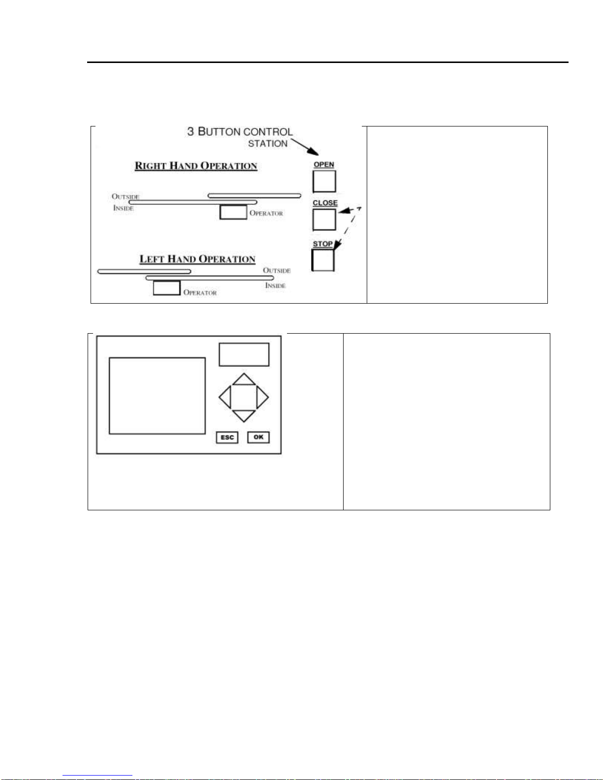
4.10 Set Operator Handing (Inside Looking Out)
1. With power off, move the gate
to the close position with the
limit plate in front of the close
limit switch.
2. While holding down STOP and
CLOSE buttons on supplied 3
button station, turn operator
power on.
3. Wait for the alarm to sound
(date and time will flash on first
power up), then release the
STOP and CLOSE buttons.
Handing is now set.
4.10.1 HCMSGOFF Parameter
The LXL operator now has the ability to
display a message if the Handing has
been changed. To enable this setting;
1. From the main menu, select ‘Set
Param’.
1. Press the UP grey arrow key and
scroll through the options to
HCMSGOFF
2. Press OK.
3. The S on Switch will start flashing
4. Use the arrow keys to Off to On
5. Press OK to save
HCMSGOFF
Switch-Off
Installation and Operations Manual —LXL Gate Operator 20
B&B ARMR
A Division of B&B Roadway and Security Solutions 0054-9001UL Revision A2
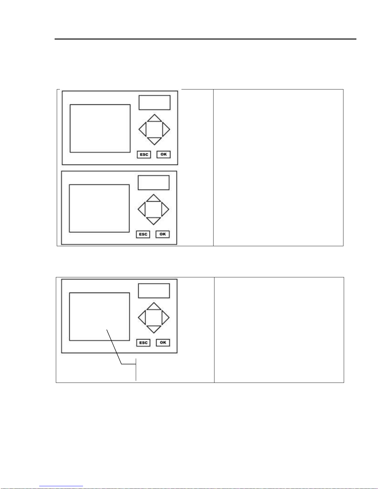
Setting The Date And Time (optional, not required)
1. Turn power on. Date and time will be
flashing. Press the ESC key.
2. This is the main menu. Use the UP
and DOWN arrow keys to select ‘Set
Clock’, and press the OK button.
3. Press OK again. A cursor flashes
under the parameter to be changed.
4. Use the UP and DOWN arrow keys
to change the value. Use the LEFT
and RIGHT arrow keys to move
between lines.
5. Press OK when finished.
NOTE: *Time format is military time
only.
4.11 Setting The Max Run Timer
1. From the main menu, select ‘Set
Param’.
2. Use the UP arrow to scroll to the
MAX RUN screen and press OK.
3. Press OK again to activate cursor.
4. Use the arrow keys to set the desired
time.
5. Press OK to save
Note: Max run time = gate length ÷ gate
speed * 2 + 5 seconds
>Stop
Set Param
Set Clock
Prg Name
Set Clock
Su 00:00
YYYY-MM-DD
2003-01-01
MAX RUN
T =20:00
Ta=00:00
Bottom number
shows elapsed time.
This manual suits for next models
8
Table of contents
Other B&B ARMR Gate Opener manuals

Popular Gate Opener manuals by other brands

Keyautomation
Keyautomation SUN Series Instructions and warnings for installation and use

HySecurity
HySecurity SlideSmart DC 15 Installation and maintenance manual

GiBiDi
GiBiDi SL 544 Instructions for installation

HySecurity
HySecurity HydraSwing 40 Programming and operations manual

HySecurity
HySecurity SlideSmart DC 15 Installation and maintenance manual

US Automatic
US Automatic PATRIOT I Installation and owner's manual


