tau ARM200 Series User manual

1
ARM200 Series
Edizione 01 - anno 2007 rev. 12 - del 02/12/2009http://www.tauitalia.com
Serie ARM200
AUTOMAZIONI PER CANCELLO A BATTENTE
AUTOMATISIERUNG VON FLÜGELTOREN
AUTOMATIC SYSTEMS FOR SWING GATES
AUTOMATISATIONS POUR PORTAIL À BATTANT
SISTEMA DE AUTOMATIZACIÓN PARA VERJAS CON BATIENTES
>ITALIANO
>ENGLISH
>DEUTSCH
>FRANÇAIS
>ESPAÑOL
TAU srl via E. Fermi, 43 – 36066 Sandrigo (Vi) Italy – Tel. +390444750190 Fax. +390444750376 E-mail: [email protected]
MANUALE D’USO E MANUTENZIONE
USE AND MAINTENANCE MANUAL
BEDIENUNGS - UND WARTUNGSANLEITUNG
MANUEL D’EMPLOI ET D’ENTRETIEN
MANUAL DE USO Y MANTENIMIENTO

2
ARM200 Series
D-MNL0ARM200
Italiano
Español
English
Français
Deutsch
I dati riportati nel presente manuale sono puramente indicativi. La TAU si riserva il diritto di modicarli in qualsiasi momento.
La Casa costruttrice si riserva il diritto di apportare modiche o miglioramenti al prodotto senza alcun preavviso. Eventuali imprecisioni
o errori riscontrabili nel presente fascicolo, saranno corretti nella prossima edizione.
All’apertura dell’imballo vericare che il prodotto sia integro. Riciclare i materiali secondo la normativa vigente.
L’installazione del prodotto dovrà essere effettuata da personale qualicato. La Ditta costruttrice Tau declina ogni responsabilità
per danni derivanti a cose e/o persone dovuti ad un’eventuale errata installazione dell’impianto o la non messa a Norma dello
stesso secondo le vigenti Leggi (vedi Direttiva Macchine).
I disegni esplosi presenti nelle ultime pagine delle presenti istruzioni sono puramente indicativi. Per i ricambi fare riferimento al relativo
listino.
Los datos describidos en este manual son puramente indicativos. La TAU se reserva el derecho de modicarlos en cualquier
momento.
El Fabricante se reserva el derecho de modicar o actualizar el producto sin aviso previo. Posibles imprecisiones o errores en este
manual serán corregidos en la próxima edición.
Cuando abra el embalaje, controle que el producto esté íntegro. Recicle los materiales según la normativa vigente.
La instalación del producto tiene que ser efectuada por personal cualicado. El Fabricante Tau no se asume ninguna
responsabilidad por lesiones a personas o averías a cosas causadas por una instalación incorrecta del equipo o la por la
inobservancia de la normativa vigente (véase Directiva de Máquinas).
Los dibujos estallados que hay en las ultimas paginas de este manual son puramente indicativos. Por los repuestos hay que hacer
referencia a la lista.
The data described in this handbook are purely a guide. TAU reserves the right to change them in any moment.
The manufacturer reserves the right to modify or improve products without prior notice. Any inaccuracies or errors found in this handbook
will be corrected in the next edition.
When opening the packing please check that the product is intact. Please recycle materials in compliance with current regulations.
This product may only be installed by a qualied tter. The manufacturer declines all liability for damage to property and/or
personal injury deriving from the incorrect installation of the system or its non-compliance with current law (see Machinery
Directive).
The exploded views on the last pages of this instruction manual are purely indicative. For the spare parts, please refer to the relevant
price list.
Les données décrites dans ce manual sont purement indicatives. La TAU se réserve le droit de les modier à n’importe quel moment.
Le Constructeur se réserve le droit d’apporter des modications ou des améliorations au produit sans aucun préavis. Les éventuelles
imprécisions ou erreurs présentes dans ce fascicule seront corrigées dans la prochaine édition.
À l’ouverture de l’emballage, vérier que le produit est intact. Recycler les matériaux suivant les normes en vigueur.
L’installation du produit devra être effectuée par du personnel qualié. Tau décline toute responsabilité pour les dommages
aux choses et/ou personnes dus à une éventuelle installation erronée de l’automatisme ou à la non-mise aux normes suivant
les lois en vigueur (voir Directive Machines).
Les plans “esplosi non lo so” qui se trouvent sur les dernières pages de ces notices techniques sont à titre indicatif. En ce qui concerne
les pièces détachées consulter la liste relative.
Die beschriebenen Daten in der vorliegenden Betriebsanleitung sind rein indikativ. TAU behält sich vor, diese in jedem Moment zu
modizieren.
Der Hersteller behält sich das Recht vor, ohne vorherige Benachrichtung Änderungen oder Verbesserungen am Produkt anzubringen.
Ungenauigkeiten oder Fehler, die in der vorliegenden Ausgabe festgestellt werden, werden in der nächsten Ausgabe berichtigt.
Beim Öffnen der Verpackung prüfen, dass das Produkt keine Schäden aufweist. Die Materialien nach den gültigen Vorschriften
recyclen.
Die Installation des Produktes muss von Fachpersonal ausgeführt werden. Die Herstellerrma TAU übernimmt keinerlei
Haftung für Personen- und/oder Sachschäden aufgrund einer falschen Installation der Anlage oder der Nichtkonformität
derselben mit den gültigen Gesetzen (siehe Maschinenrichtlinie).
Die explodierten Zeichnungen auf den letzten Seiten dieser Anleitung sind nur anzeigend. Für die Ersatzteile, bitte die entsprechende
Preisliste sehen.

3
ARM200 Series
AVVERTENZE PER L’INSTALLATORE
OBBLIGHI GENERALI PER LA SICUREZZA
A) Leggere attentamente le istruzioni prima di procedere all’installazione, in quanto forniscono importanti indicazioni concernenti la
sicurezza, l’installazione, l’uso e la manutenzione. Una errata installazione o un errato uso del prodotto può portare a gravi danni alle
persone.
B) I materiali dell’imballaggio (plastica, polistirolo, ecc.) non devono essere lasciati alla portata dei bambini in quanto potenziali fonti di pericolo.
C) Conservare le istruzioni per riferimenti futuri.
D) Questo prodotto è stato progettato e costruito esclusivamente per l’utilizzo indicato in questa documentazione. Qualsiasi altro utilizzo non
espressamente indicato potrebbe pregiudicare l’integrità del prodotto e/o rappresentare fonte di pericolo.
E) TAU declina qualsiasi responsabilità derivata dall’uso improprio o diverso da quello per cui l’automatismo è destinato.
F) Non installare il prodotto in ambiente e atmosfera esplosivi.
G) Gli elementi costruttivi meccanici devono essere in accordo con quanto stabilito dalle Norme EN 12604 e EN 12605. Per i Paesi extra-CEE, oltre
ai riferimenti normativi nazionali, per ottenere un livello di sicurezza adeguato, devono essere seguite le Norme sopra riportate.
H) TAU non è responsabile dell’inosservanza della Buona Tecnica nella costruzione delle chiusure da motorizzare, nonché delle deformazioni che
dovessero intervenire nell’utilizzo.
I) L’installazione deve essere effettuata nell’osservanza delle Norme EN 12453 e EN 12445. Il livello di sicurezza dell’automazione deve essere
C+D.
J) Prima di effettuare qualsiasi intervento sull’impianto, togliere l’alimentazione elettrica e scollegare le batterie.
K) Prevedere sulla rete di alimentazione dell’automazione un interruttore onnipolare con distanza d’apertura dei contatti uguale o superiore a 3 mm.
È consigliabile l’uso di un magnetotermico da 6A con interruzione onnipolare.
L) Vericare che a monte dell’impianto vi sia un interruttore differenziale con soglia da 0,03 A.
M) Vericare che l’impianto di terra sia realizzato a regola d’arte e collegarvi le parti metalliche della chiusura.
N) L’automazione dispone di una sicurezza intrinseca antischiacciamento costituita da un controllo di coppia. E’ comunque necessario vericarne
la soglia di intervento secondo quanto previsto dalle Norme indicate al punto I.
O) I dispositivi di sicurezza (norma EN 12978) permettono di proteggere eventuali aree di pericolo da Rischi meccanici di movimento, come ad Es.
schiacciamento, convogliamento, cesoiamento.
P) Per ogni impianto è consigliato l’utilizzo di almeno una segnalazione luminosa nonché di un cartello di segnalazione ssato adeguatamente sulla
struttura dell’insso, oltre ai dispositivi citati al punto O.
Q) Il costruttore dell’automazione declina ogni responsabilità qualora vengano installati componenti incompatibili ai ni della sicurezza e del buon
funzionamento. Per l’eventuale riparazione o sostituzione dei prodotti dovranno essere utilizzati esclusivamente ricambi originali.
R) Per la manutenzione utilizzare esclusivamente parti originali TAU.
S) Non eseguire alcuna modica sui componenti facenti parte del sistema d’automazione.
T) L’installatore deve fornire tutte le informazioni relative al funzionamento manuale del sistema in caso di emergenza e consegnare all’Utente
utilizzatore dell’impianto la “Guida Utente” allegata al prodotto.
U) Non permettere ai bambini o persone di sostare nelle vicinanze del prodotto durante il funzionamento.
W) Tenere fuori dalla portata dei bambini radiocomandi o qualsiasi altro datore di impulso, per evitare che l’automazione possa essere azionata
involontariamente.
X) Il transito tra le ante deve avvenire solo a cancello completamente aperto.
Y) L’Utente utilizzatore deve astenersi da qualsiasi tentativo di riparazione o d’intervento diretto e rivolgersi solo a personale qualicato.
Z) Tutto quello che non è previsto espressamente in queste istruzioni non è permesso.
Consigliamo di riporre tutta la documentazione relativa all’impianto all’interno o nelle immediate vicinanze della centralina.
Italiano
IMPORTANT NOTICE FOR THE INSTALLER
GENERAL SAFETY REGULATIONS
A) Please read these instructions carefully before installing the product as they contain important information concerning safety,
installation, use and maintenance. Incorrect installation or incorrect use of the product could cause serious harm to people.
B) Do not leave packing materials (plastic, polystyrene, etc.) within reach of children as such materials are potential sources of danger.
C) Store these instructions for future reference.
D) This product was designed and built strictly for the use indicated in this documentation. Any other use, not expressly indicated here, could
compromise the good condition/operation of the product and/or be a source of danger.
E) TAU declines all liability caused by improper use or use other than that for which the automated system was intended.
F) Do not install the product in explosive environments.
G) The mechanical parts must conform to the provisions of Standards EN 12604 and EN 12605. For non-EU countries, to obtain an adequate level
of safety, the Standards mentioned above must be observed, in addition to national legal regulations.
H) TAU is not responsible for failure to observe Good Technique in the construction of the closing elements to be motorised, or for any deformation
that may occur during use.
I) The installation must conform to Standards EN 12453 and EN 12445. The safety level of the automated system must be C+D.
J) Before attempting any job on the system, cut out electrical power and disconnect the batteries.
K) The mains power supply of the automated system must be tted with an all-pole switch with contact opening distance of 3mm or greater. Use of
a 6A thermal breaker with all-pole circuit break is recommended.
L) Make sure that a differential switch with threshold of 0.03 A is tted upstream of the system.
M) Make sure that the earthing system is perfectly constructed, and connect metal parts of the means of the closure to it.
N) The automated system is supplied with an intrinsic anti-crushing safety device consisting of a torque control. Nevertheless, its tripping threshold
must be checked as specied in the Standards indicated at point “I”.
O) The safety devices (EN 12978 standard) protect any danger areas against mechanical movement Risks, such as crushing, dragging, and
shearing.
P) Use of at least one indicator-light is recommended for every system, as well as a warning sign adequately secured to the frame structure, in
addition to the devices mentioned at point “O”.
Q) The manufacturer declines all liability if incompatible safety and components are installed. Only use original spare parts to repair or replace the
product.
R) For maintenance, strictly use original parts by TAU.
S) Do not in any way modify the components of the automated system.
T) The installer shall supply all information concerning manual operation of the system in case of an emergency, and shall hand over to the user
the “User Guide” supplied with the product.
U) Do not allow children or adults to stay near the product while it is operating.
W) Keep remote controls or other pulse generators away from children, to prevent the automated system from being activated involuntarily.
X) Transit through the leaves is allowed only when the gate is fully open.
Y) The user must not attempt any kind of repair or direct action whatever and contact qualied personnel only.
Z) Anything not expressly specied in these instructions is not permitted.
Keep all the documents concerning the system inside or near the central control unit.
English

4
ARM200 Series
CONSIGNES POUR L’INSTALLATEUR
RÈGLES DE SÉCURITÉ
A) Lire attentivement les instructions avant de procéder à l’installation, dans la mesure où elles fournissent des indications importantes concernant la
sécurité, l’installation, l’emploi et la maintenance. Une installation erronée ou un usage erroné du produit peut entraîner de graves conséquences
pour les personnes.
B) Les matériaux d’emballage (matière plastique, polystyrène, etc.) ne doivent pas être laissés à la portée des enfants car ils constituent des sources potentielles
de danger.
C) Conserver les instructions pour les références futures.
D) Ce produit a été conçu et construit exclusivement pour l’usage indiqué dans cette documentation. Toute autre utilisation non expressément indiquée pourrait
compromettre l’intégrité du produit et/ou représenter une source de danger.
E) TAU décline toute responsabilité qui dériverait d’usage impropre ou différent de celui auquel l’automatisme est destiné.
F) Ne pas installer le produit dans un environnement et une atmosphère explosifs.
G) Les composants mécaniques doivent répondre aux prescriptions des Normes EN 12604 et EN 12605. Pour les Pays extra-CEE, l’obtention d’un niveau de
sécurité approprié exige non seulement le respect des normes nationales, mais également le respect des Normes susmentionnées.
H) TAU n’est pas responsable du non-respect de la Bonne Technique dans la construction des fermetures à motoriser, ni des déformations qui pourraient intervenir
lors de l’utilisation.
I) L’installation doit être effectuée conformément aux Normes EN 12453 et EN 12445. Le niveau de sécurité de l’automatisme doit être C+D.
J) Couper l’alimentation électrique et déconnecter la batterie avant toute intervention sur l’installation.
K) Prévoir, sur le secteur d’alimentation de l’automatisme, un interrupteur omnipolaire avec une distance d’ouverture des contacts égale ou supérieure à 3 mm. On
recommande d’utiliser un magnétothermique de 6A avec interruption omnipolaire.
L) Vérier qu’il y ait, en amont de l’installation, un interrupteur différentiel avec un seuil de 0,03 A.
M) Vérier que la mise à terre est réalisée selon les règles de l’art et y connecter les pièces métalliques de la fermeture.
N) L’automatisme dispose d’une sécurité intrinsèque anti-écrasement, formée d’un contrôle du couple. Il est toutefois nécessaire d’en vérier le seuil d’intervention
suivant les prescriptions des Normes indiquées au point “I”.
O) Les dispositifs de sécurité (norme EN 12978) permettent de protéger des zones éventuellement dangereuses contre les Risques mécaniques du mouvement,
comme l’écrasement, l’acheminement, le cisaillement.
P) On recommande que toute installation soit doté au moins d’une signalisation lumineuse, d’un panneau de signalisation xé, de manière appropriée, sur la
structure de la fermeture, ainsi que des dispositifs cités au point “O”.
Q) Le constructeur de l’automatisme décline toute responsabilité en cas d’installation de composants incompatibles en matière de sécurité et de bon fonctionnement.
Pour toute réparation ou pour tout remplacement des produits, il faudra utiliser exclusivement des pièces de rechange originales.
R) Utiliser exclusivement, pour l’entretien, des pièces TAU originales.
S) Ne jamais modier les composants faisant partie du système d’automatisme.
T) L’installateur doit fournir toutes les informations relatives au fonctionnement manuel du système en cas d’urgence et remettre à l’Usager qui utilise l’installation
le “Guide Usager” fournie avec le produit.
U) Interdire aux enfants ou aux tiers de stationner près du produit durant le fonctionnement.
W) Eloigner de la portée des enfants les radiocommandes ou tout autre générateur d’impulsions, pour éviter tout actionnement involontaire de l’automatisme.
X) Le transit entre les vantaux ne doit avoir lieu que lorsque le portail est complètement ouvert.
Y) L’Usager qui utilise l’installation doit éviter toute tentative de réparation ou d’intervention directe et s’adresser uniquement à un personnel qualié.
Z) Tout ce qui n’est pas prévu expressément dans ces instructions est interdit.
Nous conseillons de conserver toute la documentation relative à l’installation à l’intérieur de l’armoire de commande ou à proximité immédiate.
HINWEISE FÜR DEN INSTALLATIONSTECHNIKER
ALLGEMEINE SICHERHEITSVORSCHRIFTEN
A) Die Anweisungen vor der Installation genau lesen, da sie wichtige Hinweise mit Bezug auf Sicherheit, Installation, Bedienung und Wartung liefern.
Eine falsche Installation oder ein fehlerhafter Betrieb des Produktes können zu schwerwiegenden Personenschäden führen.
B) Das Verpackungsmaterial (Kunststoff, Styropor, usw.) sollte nicht in Reichweite von Kindern aufbewahrt werden, da es eine potentielle Gefahrenquelle
darstellt.
C) Die Anleitung sollte aufbewahrt werden, um auch in Zukunft Bezug auf sie nehmen zu können.
D) Dieses Produkt wurde ausschließlich für den in diesen Unterlagen angegebenen Gebrauch entwickelt und hergestellt. Jeder andere Gebrauch, der nicht
ausdrücklich angegeben ist, könnte die Unversehrtheit des Produktes beeinträchtigen und/oder eine Gefahrenquelle darstellen.
E) Die Firma TAU lehnt jede Haftung für Schäden, die durch unsachgemäßen oder nicht bestimmungsgemäßen Gebrauch der Automatik verursacht werden, ab.
F) Das Produkt nicht in EX-Umgebung bzw. EX-Atmosphäre installieren.
G) Die mechanischen Bauelemente müssen den Anforderungen der Normen EN 12604 und EN 12605 entsprechen. Für Länder, die nicht der Europäischen Union
angehören, sind für die Gewährleistung eines entsprechenden Sicherheitsniveaus neben den nationalen gesetzlichen Bezugsvorschriften die oben aufgeführten
Normen zu beachten.
H) Die Firma TAU übernimmt keine Haftung im Falle von nicht fachgerechten Ausführungen bei der Herstellung der anzutreibenden Schließvorrichtungen sowie bei
Deformationen, die eventuell beim Betrieb entstehen.
I) Die Installation muß unter Beachtung der Normen EN 12453 und EN 12445 erfolgen. Die Sicherheitsstufe der Automatik sollte C+D sein.
J) Vor der Ausführung jeglicher Eingriffe auf der Anlage sind die elektrische Versorgung und die Batterie abzunehmen.
K) Auf dem Versorgungsnetz der Automatik ist ein omnipolarer Schalter mit Öffnungsabstand der Kontakte von über oder gleich 3 mm einzubauen. Darüber hinaus
wird der Einsatz eines Magnetschutzschalters mit 6A mit omnipolarer Abschaltung empfohlen.
L) Es sollte überprüft werden, ob vor der Anlage ein Differentialschalter mit einer Auslöseschwelle von 0,03 A zwischengeschaltet ist.
M)
Es sollte überprüft werden, ob die Erdungsanlage fachgerecht ausgeführt wurde. Die Metallteile der Schließung sollten an diese Anlage angeschlossen werden.
N) Die Automation verfügt über eine eingebaute Sicherheitsvorrichtung für den Quetschschutz, die aus einer Drehmomentkontrolle besteht. Es ist in jedem Falle
erforderlich, deren Eingriffsschwelle gemäß der Vorgaben der unter Punkt “I” angegebenen Vorschriften zu überprüfen.
O) Die Sicherheitsvorrichtungen (Norm EN 12978) ermöglichen den Schutz eventueller Gefahrenbereiche vor mechanischen Bewegungsrisiken, wie zum Beispiel
Quetschungen, Mitschleifen oder Schnittverletzungen.
P) Für jede Anlage wird der Einsatz von mindestens einem Leuchtsignal empfohlen sowie eines Hinweisschildes, das über eine entsprechende Befestigung mit
dem Aufbau des Tors verbunden wird. Darüber hinaus sind die unter Punkt ”O” erwähnten Vorrichtungen einzusetzen.
Q) Der Hersteller der Automatisierung übernimmt keinerlei Haftung, falls Bestandteile installiert werden, die – was Sicherheit und korrekten Betrieb betrifft – nicht
kompatibel sind. Zur Reparatur oder zum Ersatz der Produkte dürfen ausschließlich Originalersatzteile verwendet werden.
R) Bei der Instandhaltung sollten ausschließlich Originalteile der Firma TAU verwendet werden.
S) Auf den Komponenten, die Teil des Automationssystems sind, sollten keine Veränderungen vorgenommen werden.
T) Der Installateur sollte alle Informationen hinsichtlich des manuellen Betriebs des Systems in Notfällen liefern und dem Betreiber der Anlage das “Führer
Benutzer”, das dem Produkt beigelegt ist, übergeben.
U) Weder Kinder noch Erwachsene sollten sich während des Betriebs in der unmittelbaren Nähe der Automation aufhalten.
W) Die Funksteuerungen und alle anderen Impulsgeber sollten außerhalb der Reichweite von Kindern aufbewahrt werden, um ein versehentliches Aktivieren der
Automation zu vermeiden.
X) Der Durchgang oder die Durchfahrt zwischen den Flügeln darf lediglich bei vollständig geöffnetem Tor erfolgen.
Y)
Der Betreiber sollte keinerlei Reparaturen oder direkte Eingriffe auf der Automation ausführen, sondern sich hierfür ausschließlich an qualiziertes Fachpersonal wenden.
Z) Alle Vorgehensweisen, die nicht ausdrücklich in der vorliegenden Anleitung vorgesehen sind, sind nicht zulässig
Wir empfehlen, alle Unterlagen der Anlage in der Steuerzentrale oder in ihrer unmittelbaren Nähe aufzubewahren.
Deutsch
Français

5
ARM200 Series
ADVERTENCIAS PARA EL INSTALADOR
REGLAS GENERALES PARA LA SEGURIDAD
A) Lea con atención las instrucciones antes de proceder con la instalación, puesto que suministran importantes indicaciones sobre la
seguridad, instalación, uso y mantenimiento. Una instalación incorrecta o un uso impropio del producto puede causar graves daños
a las personas.
B) Los materiales del embalaje (plástico, poliestireno, etc.) no deben dejarse al alcance de los niños, ya que constituyen fuentes potenciales de
peligro.
C) Guarden las instrucciones para futuras consultas.
D) Este producto ha sido proyectado y fabricado exclusivamente para la utilización indicada en el presente manual. Cualquier uso diverso del
previsto podría perjudicar el funcionamiento del producto y/o representar fuente de peligro.
E) TAU declina cualquier responsabilidad derivada de un uso impropio o diverso del previsto.
F) No instale el producto en locales con atmósfera explosiva.
G) Los elementos constructivos mecánicos deben estar de acuerdo con lo establecido en las Normas EN 12604 y EN 12605. Para los países no
pertenecientes a la CEE, además de las referencias normativas nacionales, para obtener un nivel de seguridad adecuado, deben seguirse las
Normas arriba indicadas.
H) TAU no es responsable del incumplimiento de las buenas técnicas de fabricación de los cierres que se han de motorizar, así como de las
deformaciones que pudieran intervenir en la utilización.
I)
La instalación debe ser realizada de conformidad con las Normas EN 12453 y EN 12445. El nivel de seguridad de la automación debe ser C+D.
J) Quiten la alimentación eléctrica y desconecten las baterías antes de efectuar cualquier intervención en la instalación.
K) Coloquen en la red de alimentación de la automación un interruptor omnipolar con distancia de apertura de los contactos igual o superior a 3
mm. Se aconseja usar un magnetotérmico de 6A con interrupción omnipolar.
L) Comprueben que la instalación disponga línea arriba de un interruptor diferencial con umbral de 0,03 A.
M) Veriquen que la instalación de tierra esté correctamente realizada y conecten las partes metálicas del cierre.
N) La automación dispone de un dispositivo de seguridad antiaplastamiento constituido por un control de par. No obstante, es necesario comprobar
el umbral de intervención según lo previsto en las Normas indicadas en el punto “I”.
O) Los dispositivos de seguridad (norma EN 12978) permiten proteger posibles áreas de peligro de Riesgos mecánicos de movimiento, como por
ej. aplastamiento, arrastre, corte.
P) Para cada equipo se aconseja usar por lo menos una señalización luminosa así como un cartel de señalización adecuadamente jado a la
estructura del bastidor, además de los dispositivos indicados en el “O”.
Q) El fabricante de la automatización no se asume ninguna responsabilidad si se instalan componentes incompatibles para la seguridad y el
funcionamiento correcto. Para una posible reparación o sustitución de los productos, use sólo recambios originales.
R) Para el mantenimiento utilicen exclusivamente piezas originales TAU.
S) No efectúen ninguna modicación en los componentes que forman parte del sistema de automación.
T) El instalador debe proporcionar todas las informaciones relativas al funcionamiento del sistema en caso de emergencia y entregar al usuario del
equipo la “Guía Usuario” que se adjunta al producto.
U) No permitan que niños o personas se detengan en proximidad del producto durante su funcionamiento.
W) Mantengan lejos del alcance los niños los telemandos o cualquier otro emisor de impulso, para evitar que la automación pueda ser accionada
involuntariamente.
X) Sólo puede transitarse entre las hojas si la cancela está completamente abierta.
Y) El usuario no debe por ningún motivo intentar reparar o modicar el producto, debe siempre dirigirse a personal cualicado.
Z) Todo lo que no esté previsto expresamente en las presentes instrucciones debe entenderse como no permitido.
Se aconseja guardar toda la documentación de la instalación en el interior o cerca de la central.
INDICE - INHALTSVERZEICHNIS - CONTENTS - INDEX – ÍNDICE
pag. 6 Caratteristiche tecniche della serie ARM200 - Technische Eigenschaften der serie ARM200 - Technical features of the
ARM200 series - Caractéristiques techinques de la série ARM200 - Características técnicas de la serie ARM200.
pag. 7 Italiano
pag. 10 English
pag. 13 Deutsch
pag. 15 Disegni - Drawings - Zeichnen - Projets - Dibujos
pag. 20 Français
pag. 23 Español
pag. 26 Esplosi della serie ARM200 - Exploded diagrams of the ARM200 series - Explosionszeichnungen der reihe ARM200 - Vues
éclatées de la série ARM200 - Despieces de la serie ARM200.
pag. 30 Dichiarazione di conformità - Declaration of conformity - Konformitäserklärung - Declaration de conformity - Declaración de
conformidad.
pag. 31 Garanzia - Garantie - Guarantee - Garantie - Garantía
Español

6
ARM200 Series
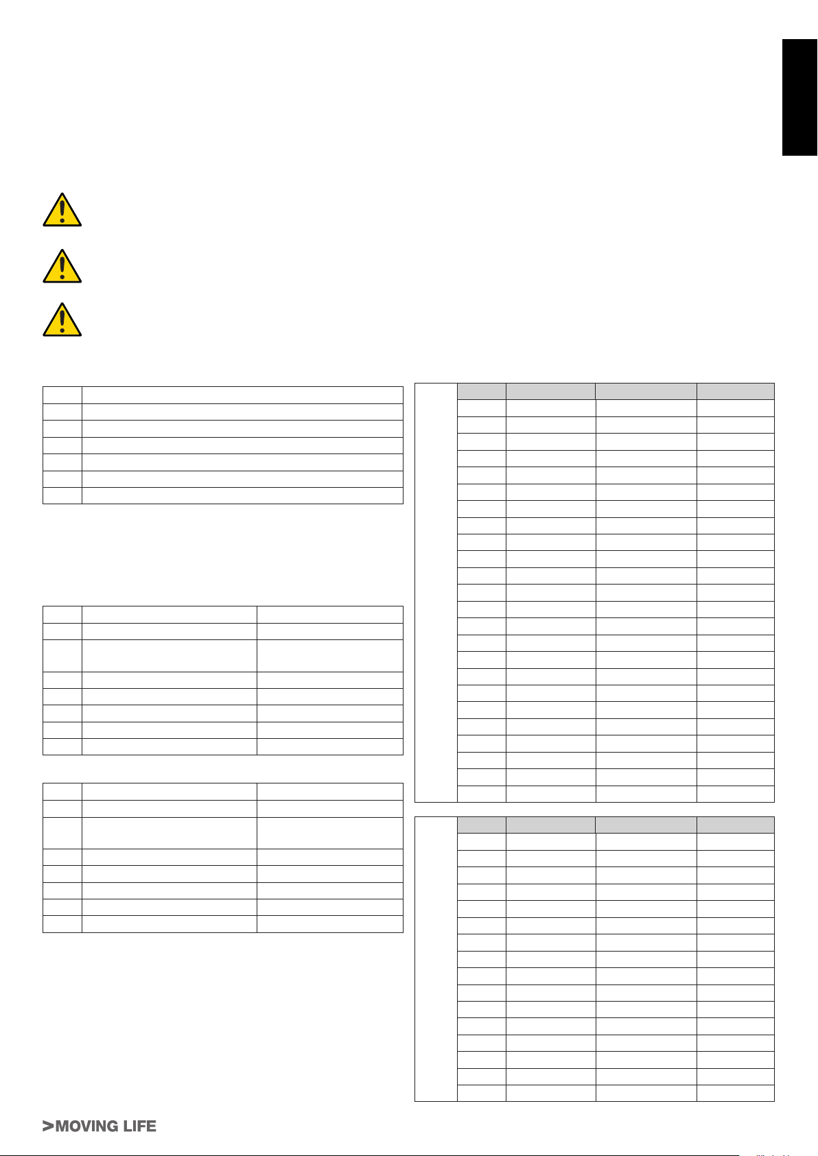
CARATTERISTICHE TECNICHE DELLA SERIE ARM200 / TECHNICAL CHARACTERISTICS OF THE ARM200
SERIES / TECHNISCHE EIGENSCHAFTEN DER SERIE ARM200 / CARACTÉRISTIQUES TECHNIQUES DE LA
SÉRIE ARM200 / CARACTERÍSTICAS TÉCNICAS DE LA SERIE ARM200
ARM225 ARM250 ARM270 ARM225BENC ARM250BENC ARM270BENC
Alimentazione \ Power input \ Versorgung \
Alimentation \ Alimentación 230 Vac ±10%
Alimentazione Motore \ Motor power input \
Motorversorgung \
Alimentation Moteur \ Alimentación motor
230 Vac ±10% 18 Vdc ±10%
Frequenza \ Frequency \ Frequenz \ Fréquence \
Frecuencia 50/60 Hz 50/60 Hz
Condensatore \ Capacitor \ Kondensator \
Condensateur \ Condensador 10 µf -
Corrente assorbita a vuoto \ Absorbed current
(no load) \ Stromaufnahme (ohne Last) \ Courant
absorbé (à vide) \ Corriente absorbida (en vacío)
1,5 A ± 10% 0,8 A ± 10%
Potenza assorbita a vuoto \ Absorbed power (no
load) \ Leistungsaufnahme (ohne Last) \ Puissance
absorbée (à vide) \ Potencia absorbida (en vacío)
250 W 20 W
Velocità motore (a vuoto) \ Motordrehzahl (leer) \
Motor speed (no load) \
Vitesse moteur (à vide) \ Velocidad motor (en vacío)
1000 rpm 1850 rpm
Corsa utile \ Useful travel \ Arbeitshub \ Course utile
\ Carretra útil 295 mm 435 mm 540 mm 295 mm 435 mm 540 mm
Intervento di termoprotezione \ Thermal protection
trips at \ Auslösung des Wärmeschutzes \
Intervention protection thermique \ Intervención de
termoprotección
140 °C (autoripristino) -
Rapporto di riduzione \ Reduction ratio \
Untersetzungsverhältnis \
Rapport de réduction \ Relación de reducción
1/24
Temperatura di esercizio \ Operating temperature \
Betriebstemperatur \
Température de fonctionnement \ Temperatura de
ejercicio
–20 °C ÷ +70 °C
Peso \ Weight \ Gewicht \ Poids \ Peso 7,8 Kg 8,1 Kg 10,4 Kg 7,8 Kg 8,1 Kg 10,4 Kg
IP Motore \ Motor IP \ Schutzart des Motors (IP) \ IP
Moteur \ IP Motor IP 44
Ciclo di lavoro \ Work cycle \ Arbeitzzyklus \ Cycle de
travail \ Ciclo de trabajo 15 % 100 %
Tempo corsa 90° \ 90° travel time \ Laufzeit, 90° \
Temps de course 90° \ Tiempo recorrido 90° 19 sec. 22 sec. 25 sec. 9 - 12 sec. 11 - 14 sec. 13 - 16 sec.
NOTA: QUANDO IL SISTEMA IN 12 VDC È ALIMENTATO UNICAMENTE DALLA BATTERIA (IN CASO DI BLACK-OUT OPPURE
IN ABBINAMENTO CON PANNELLO FOTOVOLTAICO), LE PRESTAZIONI ESPRESSE DAL MOTORIDUTTORE (FORZA E
VELOCITÀ) SI RIDUCONO DEL 30% CA.
N.B. WHEN THE SYSTEM IS IN THE 12 V DC MODE AND IS POWERED BY THE BATTERY ONLY (IN THE EVENT OF A POWER
FAILURE OR WHEN USED IN CONJUNCTION WITH A PHOTOVOLTAIC PANEL), THE GEAR MOTOR’S OUTPUT (POWER AND
SPEED) IS REDUCED BY APPROXIMATELY 30% .
ANMERKUNG: WENN DAS 12 VDC SYSTEM NUR ÜBER BATTERIE GESPEIST IST (BEI STROMAUSFALL ODER IN
KOMBINATION MIT EINEM PHOTOVOLTAICPANEEL), VERRINGERN SICH DIE LEISTUNGEN DES GETRIEBEMOTORS (KRAFT
UND GESCHWINDIGKEIT) UM CA. 30%.
ATTENTION : QUAND LE SYSTÈME À 12 VCC EST ALIMENTÉ UNIQUEMENT PAR LA BATTERIE (EN CAS DE COUPURE DE
COURANT OU BIEN ENASSOCIATION AVEC UN PANNEAU PHOTOVOLTAÏQUE), LES PERFORMANCES DU MOTORÉDUCTEUR
(FORCE ET VITESSE) DIMINUENT D’ENVIRON 30% .
NOTA: CUANDO EL SISTEMA DE 12 VDC ES ALIMENTADO ÚNICAMENTE POR LA BATERÍA (EN CASO DE CORTE DE
CORRIENTE, O BIEN COMBINADO CON PANEL FOTOVOLTAICO), LAS PRESTACIONES DEL MOTORREDUCTOR (FUERZA Y
VELOCIDAD) SE REDUCEN EN UN 30%.
I - N.B.: In presenza di vento, per l’installazione su cancelli ad ante
battenti cieche, non è garantito il funzionamento.
GB - N.B.: For The installation of blank swing gates, functioning cannot be
gua-ranteed in the presence of wind.
D - N.B.: Bei Wind wird für die Installation an durchgehenden Flügel-toren
der Betrieb nicht garantiert.
F - N.B.: En présence de vent, en cas d’installation sur des portails avec
portes battantes pleines, le fonctionnement n’est pas garanti.
E - N.B.: En presencia de viento, para la instalación en cancelas de hojas
batientes cie-gas, no se garantiza el funcionamiento.
ARM225 ARM250 ARM270
7
ARM200 Series
DESCRIZIONE
L’automazione ARM200 per cancelli a battente è un attuatore
elettromeccanico irreversibile che trasmette il movimento all’anta
tramite un sistema a vite senza ne.
L’attuatore è disponibile in più versioni in 12 Vdc e in 230 Vac.
Il sistema irreversibile garantisce il blocco meccanico dell’anta
quando il motore non è in funzione. Un comodo e sicuro sistema
di sblocco con chiave personalizzata permette la movimentazione
manuale dell’anta in caso di disservizio o di mancanza di
alimentazione.
ATTENZIONE:
Il corretto funzionamento e le caratteristiche
dichiarate si ottengono solo con accessori e
dispositivi di sicurezza TAU.
La mancanza di un dispositivo di frizione meccanica
richiede, per garantire la necessaria sicurezza
antischiacciamento, l’impiego di una centrale di
comando con frizione elettronica regolabile oppure
l’applicazione di un bordo sensibile.
L’automazione ARM200 è stata progettata e costruita
per controllare l’accesso veicolare, evitare qualsiasi
altro utilizzo.
ELEMENTI DELL’ATTUATORE (g.1)
Pos. Descrizione
1Attuatore
2Dispositivo di sblocco
3Stelo
4 Staffa attacco anta
5 Staffa posteriore
6 Coperchio morsettiera
DIMENSIONI (g.2)
INSTALLAZIONE (g.3)
Predisposizioni elettriche (Impianto tipo - ARM200)
Pos. Descrizione Cavi
1 Attuatore 4x1,5 mm²
2 Centrale di comando 3x1,5 mm²
(alimentazione)
3 Fotocellula TX 2x0,5 mm²
4 Fotocellula RX 4x0,5 mm²
5 Selettore a chiave 3x0,5 mm²
6 Lampeggiante ed antenna 2x1 mm² + 1RG58
7 Arresti meccanici -
Predisposizioni elettriche (Impianto tipo - ARM200BENC)
Pos. Descrizione Cavi
1 Attuatore 2x2,5 mm² + 3x0,5 mm²
2 Centrale di comando 3x1,5 mm²
(alimentazione)
3 Fotocellula TX 2x0,5 mm²
4 Fotocellula RX 4x0,5 mm²
5 Selettore a chiave 3x0,5 mm²
6 Lampeggiante ed antenna 2x1 mm² + 1RG58
7 Arresti meccanici -
Note:
• Per la messa in opera dei cavi elettrici utilizzare adeguati tubi
rigidi e/o essibili
• Scegliere percorsi brevi per i cavi e tenere separati i cavi di
potenza dai cavi di comando.
Veriche preliminari
Prima di installare l’automazione, apportare tutte le modiche
strutturali relative alla realizzazione dei franchi di sicurezza ed
alla protezione o segregazione di tutte le zone di schiacciamento,
cesoiamento, convogliamento e di pericolo in genere.
• Vericare che la struttura esistente abbia i necessari criteri di
robustezza e stabilità;
• gli elementi costruttivi meccanici devono essere in accordo con
quanto stabilito dalle Norme EN 12604 e EN 12605;
• lunghezza dell’anta conforme con le caratteristiche del
attuatore;
• movimento regolare ed uniforme delle ante, privo di attriti ed
impuntamenti lungo tutta la corsa;
• cerniere adeguatamente robuste ed in buono stato;
• presenza delle battute meccaniche di necorsa sia in apertura
che in chiusura;
• presenza di un’efciente presa di terra per il collegamento
elettrico dell’attuatore.
Si raccomanda di effettuare gli eventuali interventi fabbrili prima di
installare l’automazione.
Lo stato della struttura del cancello inuenza direttamente
l’afdabilità e la sicurezza dell’automazione.
Quote di installazione (g.4)
Determinare la posizione di montaggio dell’attuatore facendo
riferimento alla g.4.
Vericare attentamente che la distanza tra l’anta aperta ed
eventuali ostacoli (pareti, recinzioni etc.) sia superiore all’ingombro
dell’attuatore.
A
R
M
2
2
5
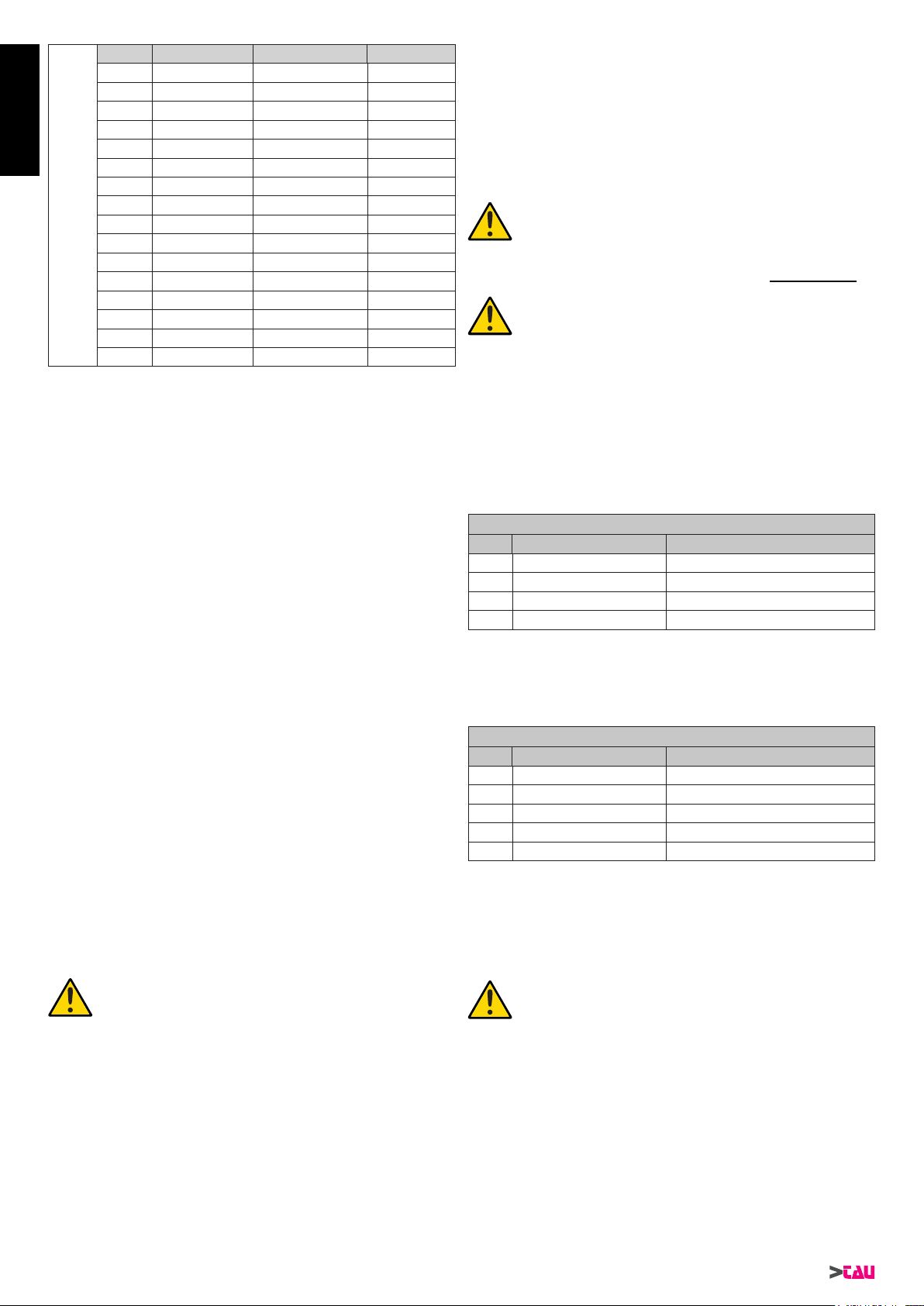
X° A (mm) B (mm) C (mm)
90 80 ÷ 85 110 ÷ 200 20 mm
90 90 110 ÷ 195 20 mm
90 95 110 ÷ 190 20 mm
90 100 110 ÷ 185 20 mm
90 105 110 ÷ 180 20 mm
90 110 ÷ 115 110 ÷ 175 20 mm
90 120 110 ÷ 170 20 mm
90 125 110 ÷ 165 20 mm
90 130 110 ÷ 160 20 mm
90 135 110 ÷ 155 20 mm
90 140 110 ÷ 150 20 mm
90 145 ÷ 150 110 ÷ 145 20 mm
90 155 110 ÷ 140 20 mm
90 160 110 ÷ 135 20 mm
90 165 110 ÷ 130 20 mm
90 170 110 ÷ 125 20 mm
90 175 ÷ 180 110 ÷ 120 20 mm
100 100 ÷ 120 110 ÷ 150 20 mm
100 125 110 ÷ 145 20 mm
100 130 110 ÷ 140 20 mm
100 135 110 ÷ 135 20 mm
100 140 110 ÷ 130 20 mm
100 145 110 ÷ 125 20 mm
100 150 110 ÷ 120 20 mm
A
R
M
2
5
0
X° A (mm) B (mm) C (mm)
90 80 ÷ 175 115 ÷ 250 20 mm
90 180 ÷ 185 115 ÷ 245 20 mm
90 190 115 ÷ 240 20 mm
90 195 115 ÷ 235 20 mm
90 200 115 ÷ 230 20 mm
100 100 ÷ 150 115 ÷ 250 20 mm
100 155 115 ÷ 245 20 mm
100 160 115 ÷ 240 20 mm
100 165 115 ÷ 235 20 mm
100 170 115 ÷ 230 20 mm
100 175 115 ÷ 225 20 mm
100 180 115 ÷ 220 20 mm
100 185 115 ÷ 215 20 mm
100 190 115 ÷ 210 20 mm
100 195 115 ÷ 205 20 mm
100 200 115 ÷ 200 20 mm
ITALIANO
8
ARM200 Series
A
R
M
2
7
0
X° A (mm) B (mm) C (mm)
90 80 ÷ 235 120 ÷ 300 20 mm
90 240 120 ÷ 295 20 mm
90 245 120 ÷ 290 20 mm
90 250 120 ÷ 285 20 mm
100 130 ÷ 195 120 ÷ 300 20 mm
100 200 120 ÷ 295 20 mm
100 205 120 ÷ 290 20 mm
100 210 120 ÷ 285 20 mm
100 215 120 ÷ 280 20 mm
100 220 120 ÷ 275 20 mm
100 225 120 ÷ 270 20 mm
100 230 120 ÷ 265 20 mm
100 235 120 ÷ 260 20 mm
100 240 120 ÷ 255 20 mm
100 245 120 ÷ 250 20 mm
100 250 120 ÷ 245 20 mm
Quando la quota “C” risulta essere superiore/inferiore a 20 mm,
aumentare/diminuire la quota “B” della differenza (es: se C=
25mm, aumentare “B” di 5mm), vericando che sia entro i limiti
riportati in tabella.
Nel caso in cui le dimensioni del pilastro o la posizione della
cerniera non permettano di contenere la quota Bnella misura
desiderata, è necessario effettuare una nicchia sul pilastro come da
g.5. Le dimensioni della nicchia devono essere tali da consentire
un’agevole installazione, rotazione dell’attuatore ed azionamento
del dispositivo di sblocco. Le staffe di ssaggio sono progettate
per fornire piccoli aggiustamenti in ambedue le direzioni (g.5A);
attenersi comunque sempre alle misure riportate in tabella.
Rispettare i valori di tabella e oliare i cardini del cancello.
1_ Fissare la staffa posteriore nella posizione determinata
precedentemente. Nel caso di pilastro in ferro utilizzare n°4 viti
autoperforanti Ø 6,3 mm (g.6). Nel caso di pilastro in muratura
(g.7), utilizzare n°4 tasselli M8 (dopo averla assemblata,
g.7A).
Durante le operazioni di ssaggio vericare con una livella
la perfetta orizzontalità della staffa.
2_ Predisporre l’operatore per il funzionamento manuale (vedi
par. SBLOCCO MANUALE).
3_ Estrarre completamene lo stelo no a battuta, (1 g.8).
4_ Ribloccare l’operatore (vedi par. RIPRISTINO DEL
FUNZIONAMENTO NORMALE).
5_ Ruotare di mezzo giro lo stelo in senso orario, (2 g.8).
6_ Assemblare la staffa anteriore come indicato in g.9. Fissare la
vite con relativo dado (g.9).
7_ Dopo aver asportato il coperchio morsettiera, ancorare
l’attuatore alla staffa posteriore usando la vite ed il relativo
dado in dotazione (vedi 1 g.10).
ATTENZIONE: È possibile movimentare manualmente
l’attuatore solo ed esclusivamente se installato sul
cancello ed in posizione sbloccata (vedi par. SBLOCCO
MANUALE).
ATTENZIONE: vericare che, ad anta chiusa, la
fusione dell’attuatore non vada a toccare la staffa
posteriore (g.10), eventualmente regolare di
conseguenza.
8_ Vericare la quota “L” come da tabella (g.4).
9_ Appoggiare la staffa appena assemblata all’anta del cancello
completamente chiuso e segnare i punti di ssaggio (avendo
cura della planarità, g.11).
Prima di passare alla fase successiva eseguire la seguente
prova:
10_ Sbloccare l’attuatore (vedi par. SBLOCCO MANUALE) e
vericare manualmente che il cancello sia libero di aprirsi
completamente fermandosi sugli arresti meccanici di
necorsa e che il movimento dell’anta sia regolare e privo di
attriti.
11_ Eseguire gli interventi correttivi necessari e ripetere dal punto
10. Aprire manualmente il cancello no all’angolo massimo
voluto.
12_ Avvitare il braccio no a che la staffa anteriore possa
sovrapporsi alla posizione appena marcata sull’anta.
Se l’operazione è possibile l’installazione è corretta.
Questo metodo si può usare per stabilire dove ssare la staffa
attacco anta per ogni angolo di apertura (X°) voluto, a condizione
che ciò sia possibile (parametri A e B e corsa utile dell’attuatore
permettendo).
13_ ssare la staffa anteriore nella posizione marcata (g. 12)
vericando la quota di g. 13, avendo cura della planarità.
Nota bene: nel caso la struttura del cancello
non permetta un solido ssaggio della staffa è
necessario intervenire sulla struttura del cancello
creando una solida base d’appoggio.
Nota: per una completa sicurezza si fa obbligo di
installare, se non presenti, gli arresti meccanici
(battenti a pavimento) con tappo in gomma in
apertura e in chiusura (7 g. 3), in modo che
intervengano subito prima dei ne-corsa meccanici
del pistone.
CABLAGGIO DELL’ATTUATORE
Nella parte posteriore dell’attuatore è stata alloggiata una morset-
tiera per il collegamento del motore e per la messa a terra
dell’attuatore (gg.14-15).
Eseguire i collegamenti del motore e della massa a terra facendo
riferimento alle gg.14-15 ed alla tabella.
ARM200 - 230 Vac
POS. COLORE DESCRIZIONE
1 Blu
Comune
2 Marrone Fase 1
3 Nero Fase 2
T Giallo / Verde Messa a terra
Collegare il condensatore in dotazione in parallelo alle 2 fasi del
motore (contatti 2 e 3) facendo attenzione a non cortocircuitare i
due li, al ne di evitare possibili scariche dovute a correnti residue.
Usare esclusivamente centrali con frizione elettrica.
ARM200BENC - 12 Vdc
POS. COLORE DESCRIZIONE
1 Bianco
Segnale encoder
2 Blu Negativo encoder
3 Marrone Positivo encoder
4 Nero Neutro motore
5 Rosso Fase motore
Usare esclusivamente centraline dotate di frizione elettrica.
Si consiglia di utilizzare il cavo composto della TAU srl, cod. M-
03000010CO;
MESSA IN FUNZIONE
ATTENZIONE: Prima di effettuare qualsiasi
intervento sull’impianto o sull’attuatore, togliere
l’alimentazione elettrica.
Seguire scrupolosamente i punti I, J, K, L ed M degli OBBLIGHI
GENERALI PER LA SICUREZZA.
Seguendo lo schema di g.3 e la relativa tabella (vedi par.
INSTALLAZIONE), predisporre le canalizzazioni ed effettuare i
collegamenti elettrici della centrale di comando e degli accessori.
Scegliere percorsi brevi per i cavi e tenere separati i cavi di potenza
dai cavi di comando.
1) Alimentare il sistema e vericare lo stato dei leds come da
istruzioni della centrale di comando.
2) Programmare la centrale di comando secondo le proprie
esigenze come da istruzioni allegate.
ITALIANO

9
ARM200 Series
• effettuare una manutenzione periodica;
• in caso di guasto, togliere l’alimentazione e gestire il cancello
manualmente solo se possibile e sicuro. Astenersi da ogni
intervento e chiamare un tecnico autorizzato.
MANUTENZIONE
Al ne d’assicurare nel tempo un corretto funzionamento ed un
costante livello di sicurezza è opportuno eseguire, con cadenza
semestrale, un controllo generale dell’impianto. Nel fascicolo ‘Guida
per l’Utente’ è stato predisposto un modulo per la registrazione
degli interventi da farsi regolarmente.
ATTENZIONE: nessuna persona ad eccezione
del manutentore, che deve essere un tecnico
specializzato, deve poter comandare l’automatismo
durante la manutenzione.
Si raccomanda perciò di togliere l’alimentazione di rete, evitando
così anche il pericolo di shock elettrici. Se, invece, l’alimentazione
dovesse essere presente per talune veriche, si raccomanda di
controllare o disabilitare ogni dispositivo di comando (telecomandi,
pulsantiere, etc.) ad eccezione del dispositivo usato dal
manutentore.
Gli attuatori ARM200 e ARM200BENC necessitano di poca
manutenzione; il loro buon funzionamento dipende dallo stato del
cancello: perciò descriveremo brevemente anche le operazioni da
fare per avere un cancello sempre efciente.
Manutenzione ordinaria
Ciascuna delle seguenti operazioni deve essere eseguita ogni 6
mesi per un uso domestico (circa 3000 cicli di lavoro) e ogni 2
mesi per un uso intensivo, es. condominiale (sempre ogni 3000
cicli di lavoro).
Cancello:
- lubricare ed ingrassare i cardini del cancello.
Impianto di automazione:
- vericare il corretto funzionamento dei dispositivi di sicurezza
(fotocellule, bordo sensibile, etc.) con tempi e modi descritti dai
fornitori;
- ingrassare (con l’ingrassatore) la vite senza ne accessibile
dalla parte inferiore dell’attuatore; si consiglia di utilizzare
grasso al sapone di litio complesso della SYNECO.
- vericare lo stato di carica della batteria con un tester per batterie
piombo-acido; in caso di sostituzione utilizzare una batteria
originale e riciclare l’unità scarica secondo la normativa vigente
(in alternativa TAU consiglia di utilizzare batterie FIAMM).
NOTA: Può vericarsi, nel corso del tempo, la
formazione di una sottile riga di ossido sullo
stelo dell’attuatore. Questo fenomeno è dovuto
all’aggiunta di materiale all’atto della saldatura
del tubo/stelo e NON pregiudica in alcun modo
nè la qualità dello stelo stesso, nè il normale
funzionamento del motoriduttore. Si consiglia di
pulire periodicamente lo stelo con appositi preparati
per l’acciaio inox.
Manutenzione straordinaria o rotture
Se dovessero rendersi necessari interventi non banali su parti
elettromeccaniche, si raccomanda la rimozione del componente
dove il guasto è localizzato per consentire una riparazione in
ofcina dai tecnici della casa madre o da essa autorizzati.
Consigliamo di riporre tutta al documentazione relativa
all’impianto all’interno o nelle immediate vicinanze della
centralina.
APPLICAZIONI PARTICOLARI
Non sono previste applicazioni diverse da quella descritta.
RUMOROSITÀ
Il rumore aereo prodotto dal motoriduttore in condizioni normali di
utilizzo è costante e non supera i 70 dB.
PROVA DELL’AUTOMAZIONE
• Procedere alla verica funzionale e minuziosa dell’automazione
e di tutti gli accessori installati, prestando particolare attenzione
ai dispositivi di sicurezza.
• Consegnare all’utilizzatore nale il fascicolo “Guida Utente” ed
il registro di Manutenzione.
• Illustrare ed istruire correttamente l’utilizzatore sul corretto
funzionamento ed utilizzo dell’automazione.
• Segnalare all’utilizzatore le zone di potenziale pericolo
dell’automazione.
SBLOCCO MANUALE
Nel caso si renda necessario movimentare manualmente
l’automazione, per mancanza di alimentazione o disservizio
dell’attuatore, agire come di seguito:
1_ Togliere l’alimentazione elettrica agendo sull’interruttore
differenziale (anche in caso di mancanza di alimentazione).
2_ Far scorrere il cappuccio protettivo, g.16;
3_ Inserire la chiave e ruotarla di 90°, g.17.
4_ Ruotare, come mostrato in g.18, la leva di sblocco verso l'alto
per sbloccare l'attuatore.
5_ Effettuare manualmente la manovra di apertura o di chiusura
dell’anta.
Nota bene: Per mantenere l’attuatore in funziona-
mento manuale è assolutamente necessario lasciare
il dispositivo di sblocco nella posizione attuale e
l’impianto disalimentato.
RIPRISTINO DEL FUNZIONAMENTO NORMALE
Per ripristinare le condizioni di funzionamento normale agire come
di seguito:
1_ Richiudere la leva di sblocco verso il basso.
2_ Ruotare di 90° la chiave di sblocco ed estrarla.
3_ Richiudere il coperchietto di protezione.
4_ Alimentare l’impianto ed eseguire alcune manovre per vericare
il corretto ripristino di tutte le funzioni dell’automazione.
USO
Gli attuatori ARM225 / ARM225BENC, ARM250 / ARM250BENC
e ARM270 / ARM270BENC sono stati progettati per movimentare
ante della lunghezza massima rispettiva di m. 3.0, 4,0 e 5,0.
Si fà espresso divieto di utilizzare l’apparecchio per scopi diversi
o in circostanze diverse da quelle menzionate. Normalmente,
la centralina elettronica installata (che deve avere la frizione
elettrica incorporata) consente di selezionare il funzionamento:
automatico : un impulso di comando esegue l’apertura e la
chiusura del cancello
semiautomatico: un impulso di comando esegue l’apertura o la
chiusura del cancello.
In caso di mancanza di energia elettrica, il cancello può funzionare
ugualmente grazie alla possibilità di gestione manuale, per la
quale è necessario agire sul dispositivo di sblocco manuale. I
modelli ARM200BENC, alimentabili con batteria tampone, sono in
grado di effettuare almeno 15 cicli completi (apertura e chiusura)
in modo autonomo.
Si ricorda che si è in presenza di un dispositivo automatico e
alimentato da corrente elettrica, perciò nell’utilizzo devono essere
usate le dovute precauzioni. In particolare, si ammonisce di:
• non toccare l’apparecchio con mani bagnate e/o piedi bagnati
o nudi;
• togliere la corrente prima di aprire la scatola comandi e/o
l’attuatore;
• non tirare il cavo di alimentazione per staccare la presa di
corrente;
• non toccare il motore se non siete sicuri che sia raffreddato;
• mettere in movimento il cancello solo quando è completamente
visibile;
• tenersi fuori dal raggio di azione del cancello se questo è in
movimento: aspettare no a che non sia fermo;
• non lasciare che bambini o animali giochino in prossimità del
cancello;
• non lasciare che bambini o incapaci usino il telecomando o altri
dispositivi di azionamento;
ITALIANO
10
ARM200 Series
DESCRIPTION
The ARM200 automated system for swing gates is an electro-
mechanical non-reversing actuator that transmits motion to the leaf
via a worm screw system.
The actuator is available in more versions in 12 Vdc and 230 Vac.
The non-reversing system ensures the leaf is mechanically locked
when the motor is not operating. A convenient and safe release
system with customised key makes it possible to manually move
the leaf in the event of a malfunction or of a power failure.
ATTENTION:
The correct operation and the declared specications
only apply if TAU accessories and safety devices
are used.
In the absence of a mechanical clutch, the use of
a control unit with an adjustable electronic clutch,
or the installation of a sensitive edge, is required in
order to ensure crush-proof safety.
The ARM200 automated system was designed and
built for controlling vehicle access. Avoid any other
use whatever.
ACTUATOR PARTS (g.1)
Pos. Description
1Actuator
2 Release device
3 Rod
4Wing connection bracket
5 Rear bracket
6Terminal board cover
DIMENSIONS (g.2)
INSTALLATION (g.3)
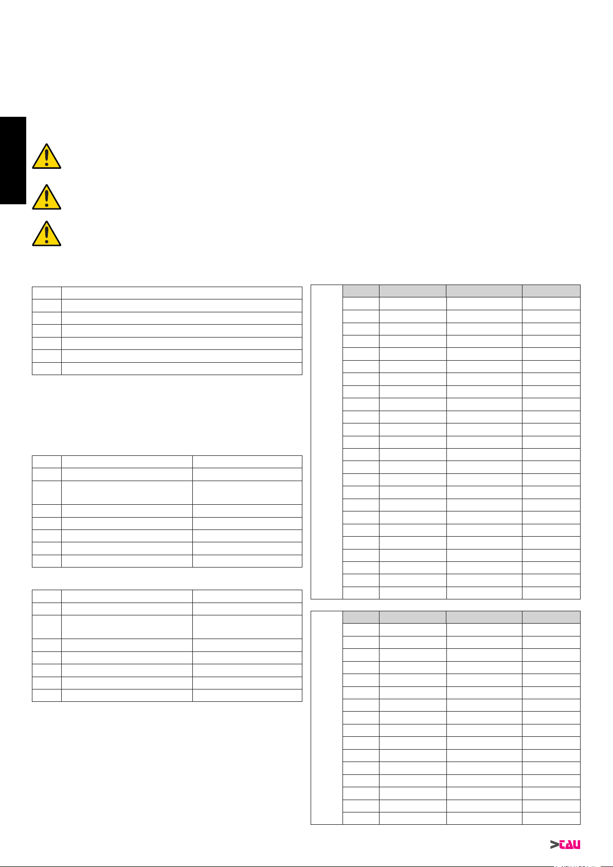
Electrical set-up (standard system - ARM200)
Pos. Description Cables
1 Attuatore 4x1,5 mm²
2 Control unit 3x1,5 mm²
(power supply)
3 TX photocells 4x0,5 mm²
4 RX photocells 2x0,5 mm²
5 Key-operated selector switch 3x0,5 mm²
6 Flashing light and aerial 2x1 mm² + 1RG58
7 Mechanical stops -
Electrical set-up (standard system
- ARM200BENC)
Pos. Description Cables
1 Attuatore 2x2,5 mm² + 3x0,5 mm²
2 Control unit 3x1,5 mm²
(power supply)
3 TX photocells 4x0,5 mm²
4 RX photocells 2x0,5 mm²
5 Key-operated selector switch 3x0,5 mm²
6 Flashing light and aerial 2x1 mm² + 1RG58
7 Mechanical stops -
Notes:
• Use suitable tubes and/or hoses to lay electric cables
• Choose short routes for cables and keep power cables separate
from control cables.
Preliminary checks
Prior to installing the automation, make all structural modications
in order to ensure safety distances and protect and segregate
areas in which people may be exposed to the risk of crushing,
shearing, dragging or similar dangers.
• Make sure the existing structure is sufciently sturdy and
stable;
• the mechanical parts must conform to the provisions of
Standards EN 12604 and EN 12605;
• leaf length in compliance with the actuator specications;
• regular and uniform movement of the leaves, without any
friction and dragging during their entire travel;
• stiff hinges in good conditions;
• presence of both opening and closing mechanical limit stops;
• presence of an efcient earthing for electrical connection of the
actuator.
Perform any necessary metalwork job before installing the
automated system.
The condition of the gate structure directly affects the
reliability and safety of the automated system.
Installation dimensions (g.4)
Determine the tting position of the actuator with reference to
g.4.
Check with care if the distance between the open leaf and
any obstacles (walls, fences etc.) is higher than the actuator
dimensions.
A
R
M
2
2
5
X° A (mm) B (mm) C (mm)
90 80 ÷ 85 110 ÷ 200 20 mm
90 90 110 ÷ 195 20 mm
90 95 110 ÷ 190 20 mm
90 100 110 ÷ 185 20 mm
90 105 110 ÷ 180 20 mm
90 110 ÷ 115 110 ÷ 175 20 mm
90 120 110 ÷ 170 20 mm
90 125 110 ÷ 165 20 mm
90 130 110 ÷ 160 20 mm
90 135 110 ÷ 155 20 mm
90 140 110 ÷ 150 20 mm
90 145 ÷ 150 110 ÷ 145 20 mm
90 155 110 ÷ 140 20 mm
90 160 110 ÷ 135 20 mm
90 165 110 ÷ 130 20 mm
90 170 110 ÷ 125 20 mm
90 175 ÷ 180 110 ÷ 120 20 mm
100 100 ÷ 120 110 ÷ 150 20 mm
100 125 110 ÷ 145 20 mm
100 130 110 ÷ 140 20 mm
100 135 110 ÷ 135 20 mm
100 140 110 ÷ 130 20 mm
100 145 110 ÷ 125 20 mm
100 150 110 ÷ 120 20 mm
A
R
M
2
5
0
X° A (mm) B (mm) C (mm)
90 80 ÷ 175 115 ÷ 250 20 mm
90 180 ÷ 185 115 ÷ 245 20 mm
90 190 115 ÷ 240 20 mm
90 195 115 ÷ 235 20 mm
90 200 115 ÷ 230 20 mm
100 100 ÷ 150 115 ÷ 250 20 mm
100 155 115 ÷ 245 20 mm
100 160 115 ÷ 240 20 mm
100 165 115 ÷ 235 20 mm
100 170 115 ÷ 230 20 mm
100 175 115 ÷ 225 20 mm
100 180 115 ÷ 220 20 mm
100 185 115 ÷ 215 20 mm
100 190 115 ÷ 210 20 mm
100 195 115 ÷ 205 20 mm
100 200 115 ÷ 200 20 mm
ENGLISH
11
ARM200 Series
A
R
M
2
7
0
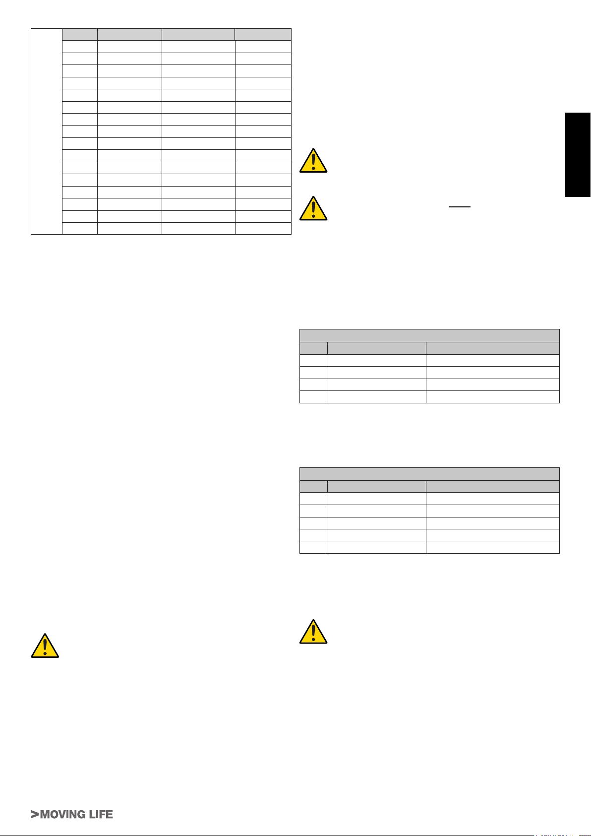
X° A (mm) B (mm) C (mm)
90 80 ÷ 235 120 ÷ 300 20 mm
90 240 120 ÷ 295 20 mm
90 245 120 ÷ 290 20 mm
90 250 120 ÷ 285 20 mm
100 130 ÷ 195 120 ÷ 300 20 mm
100 200 120 ÷ 295 20 mm
100 205 120 ÷ 290 20 mm
100 210 120 ÷ 285 20 mm
100 215 120 ÷ 280 20 mm
100 220 120 ÷ 275 20 mm
100 225 120 ÷ 270 20 mm
100 230 120 ÷ 265 20 mm
100 235 120 ÷ 260 20 mm
100 240 120 ÷ 255 20 mm
100 245 120 ÷ 250 20 mm
100 250 120 ÷ 245 20 mm
When measurement “C” is greater/smaller than 20 mm, increase/
diminish measurement “B” by the difference (e.g.: if C= 25mm,
increase “B” by 5mm), making sure that it does not exceed the
limits shown in the table.
If the pillar dimensions or the hinge position do not allow the
installation of the actuator, a niche on the pillar, as shown in Fig.
5, should be created in order to maintain the A dimension as
determined. The niche should be dimensioned in such a way to
enable easy installation, actuator rotation and operation of the
release device. The mounting brackets are designed to enable
small adjustments in both directions (g.5A). In any case, always
refer to the measurements shown in the table.
Please keep to the values given in the table and oil the gate’s
hinges.
1_ Fix the rear bracket in the position determined before. In the
event of iron pillar carefully use n°4 Ø 6,3 mm self-drilling screw
(g.6). In the event of brick pillar (g.7), use n°4 M8 bolts (after
you have assembled it, g.7A).
During the fastening operations, check if the bracket is
perfectly horizontal by means of a level.
2_ Set the operator for manual operation (see paragraph MANUAL
RELEASE).
3_ Completely extend the rod till it reaches the limit stop (1 g.8).
4_ Lock the operator again (see paragraph RESTORING NORMAL
OPERATION).
5_ Turn the rod clockwise half a revolution (2 g.8).
6_ Assemble the front bracket as shown in g.9. Fasten the screw
using the special nut (g.9).
7_ After removing the terminal board cover, anchor the actuator
to the rear bracket using the screw and nut supplied (see 1
g.10);
ATTENTION: The actuator can be moved by hand only if
it is installed on the gate and in released position (see
paragraph MANUAL RELEASE).
ATTENTION: carefully verify that, when gate is
closed, the actuator’s rear do not touch the bracket
(see g. 10). If so adjust the setting accordingly.
8_ Check measurement “L” according to the table (g.4).
9_ rest the bracket that has just been xed, onto the wing of the
completely closed gate and mark the xing points (make sure it
is level, see g. 11).
Before going on to the next phase please carry out the following
test:
10_ Release the actuator (see paragraph MANUAL RELEASE)
and manually check if the gate can completely open without
hindrances and stop at the mechanical travel stops as well as
if the leaf moves regularly without any friction.
11_ Carry out the necessary corrective measures and repeat from
point 10. Manually open the gate to the maximum required
angle;
12_ Tighten the arm until the front bracket nds itself over the
position just marked on the gate.
If the small bracket does cover the position marked it means
installation has been done correctly.
This method can be used to establish where the small bracket will
have to be welded for each opening angle (X°) required provided
it is possible (parameters A and B and the actuator’s useful travel
permitting).
13_ fasten the gate mounting bracket in the position indicated
(g.12), referring to the dimensions shown in g. 13 and
ensuring the planarity of the assembly.
Note: if the gate structure does not allow a x
bracket fastening it is necessary to create a sturdy
supporting base in the gate structure.
Note: for complete safety, the mechanical stops with
rubber cap (oor stops) must be tted in opening
and closing of the gate (7 g.3), in order that they
intervene just before the mechanical piston stops.
WIRING THE ACTUATOR
A terminal board is tted in the lower part of the actuator for the
connection of the motor, of any limit switch and for the earthing of
the actuator. (gg.14-15).
Connect the motor and the earthing with reference to g.14-15 and
to the table.
ARM200 - 230 Vac
POS. COLOR DESCRIPTION
1 Blue
Common cable
2 Brown Phase 1
3 Black Phase 2
T Yellow / Green Earthing
Connect up the condenser in parallel to the 2 phases of the motor
(terminals 2 and 3). Warning! Do not short-circuit the two wires as
this may cause discharges because of the current remaining in the
wires. Use control units with torque limiting device only.
ARM200BENC - 12 Vdc
POS. COLOR DESCRIPTION
1 White
Encoder signal
2 Blue Encoder negative
3 Brown Encoder positive
4 Blue Motor neutral
5 Red Motor phase
Only use control units tted with an electric clutch.
TAU srl recommends its composite cable, Code M-03000010CO;
START-UP
ATTENTION: Cut power before any job on the
system or on the actuator.
Carefully observe points 10, 11, 12, 13 and 14 of the SAFETY
GENERAL RULES.
With reference to the indications in g.3 and in the table (see
paragraph INSTALLATION), set the ducts and carry out the
electrical connections of the control board and of the chosen
accessories.
Choose short routes for cables and keep power cables separate
from control cables.
1) Power the system and check the status of the LED’s according
to the control unit instructions.
2) Program the control board according to the needs by following
the given instructions.
ENGLISH
12
ARM200 Series
MAINTENANCE
To censure trouble-free operation and a constant safety level, an
overall check of the system should be carried out every 6 months.
A form for recording operations has been included in the “User
Guide” booklet.
ATTENTION: no-one, except for the maintenance
man, who must be a specialised technician,
must be able to use the automatic system during
maintenance.
Switch off the mains power supply to eliminate the risk of
electrocution. If the power supply must be left on for certain
operations, each control device should be checked or disabled
(remote controls, push button strips, etc.) except for the one used
by the maintenance man.
The ARM200 / ARM200BENC actuators need very little
maintenance. However, as the gate must be in good working order
for them to work properly, the operations required to keep it in
perfect condition are described below.
Routine maintenance
Each of the following operations must be carried out every 6
months for domestic use (approx. 3000 work cycles) and every 2
months for intensive use such as blocks of ats (always 3000 work
cycles).
Gate:
- lubricate and grease the hinges of the gate.
Automation system:
- check the safety devices (photocells, pneumatic edge, etc.)
work according to the manufacturer’s instructions;
- grease (with a greaser) the worm screw from underneath the
actuator (see g.12); TAU srl recommends using the complex
lithium soap grease produced by SYNECO.
- use a tester for lead-acid batteries to check whether the
battery is charged; if it needs replacing use an original battery
and recycle the at one in compliance with current legislation
(alternatively, TAU srl recommends using FIAMM batteries).
N.B.: With use, a thin line of oxide may form on the
actuator stem. This is due to the materials addition
when welding the tube/stem. However, in NO WAY
does this affect the quality or normal operation of
the gearmotor. We recommend the stem be cleaned
regularly using special products for stainless steel.
Extraordinary maintenance or breakage
If major work on electromechanical parts must be carried out, the
faulty component should be removed and repaired in the workshop
by the maker’s or other authorised technicians.
Keep all the documents concerning the system inside or near
the control unit.
SPECIAL APPLICATIONS
There is no special application other than the described use.
NOISE LEVELS
Airborne noise generated by the gearmotor in normal operating
conditions is constant and does not exceed 70 dB.
TESTING THE AUTOMATED SYSTEM
• Carefully check operating efciency of the automated system
and of all accessories connected to it, paying special attention
to the safety devices.
• Hand the “User Guide” to the nal user together with the
Maintenance register.
• Explain correct operation and use of the automated system to
the user.
• Indicate the potentially dangerous areas of the automated
system to the user.
MANUAL RELEASE
If the automated system needs to be moved manually due to a
power lack or to an actuator malfunction, proceed as follows:
1_ Cut power by means of the safety circuit breaker (even in the
event of a power lack).
2_ Slide the protective cap, g.16;
3_ Insert the key and turn it 90°, g.17.
4_ As shown in g.18, rotate the release lever upward in order to
release the actuator.
5_ Open or close the leaf manually.
Note: To hold the actuator in manual operation the
release device should be left in its current positions
and the system should be without power.
RESTORING NORMAL OPERATION
To restore normal operating conditions, proceed as follows:
1_ Lock the release lever by rotating it downward.
2_ Turn 90° the release key and remove it.
3_ Close the protection cover.
4_ Power up the system and perform some movements in order to
check the correct restoring of every function of the automated
system.
USE
Actuators ARM225 - ARM225BENC, ARM250 - ARM250BENC
and ARM270 - ARM270BENC are designed to move gates with a
maximum length of, respectively, 3.0, 4.0 and 5.0 metres.
It is expressly forbidden to use the device for any other
purposes or under any other circumstances other than those
mentioned. The electronic control unit (which must be tted with
an electric clutch) allows the following functions to be selected:
automatic : a command impulse opens and shuts the gate
semiautomatic : a command impulse opens or shuts the gate.
In the event of a power failure, the gate may be moved manually by
activating the “manual release” device. Mod. ARM200BENC can
be powered by a buffer battery and is able to perform at least 15
complete cycles (open and close) on its own.
This is an electrically powered automatic device and should
therefore be used with care. In particular:
• do not touch with wet hands and/or wet or bare feet;
• disconnect the power supply before opening the control box
and/or the actuator;
• do not pull the plug out by its cable;
• do not touch the motor unless you are certain it is cool;
• only operate the gate when it is completely visible;
• do not approach the gate while it is moving;
• do not allow children or animals to play near the gate;
• do not allow children or disabled people to use the remote
control or other operating devices;
• carry out routine maintenance;
• in the case of a fault, disconnect the power supply and only
move the gate if it is possible and safe to do so. Do not touch
the gate and call in an authorised technician.
ENGLISH
13
ARM200 Series
BESCHREIBUNG
Die Automation ARM200 für Flügeltore ist ein irreversibler
elektromechanischer Antrieb, der über ein Schneckensystem die
Bewegung auf den Flügel überträgt.
Der Antrieb ist in mehreren Versionen erhältlich in 12 Vdc und 230
Vac.
Das irreversible System gewährleistet die mechanische
Verriegelung des Flügels, wenn der Motor nicht in Betrieb ist.
Ein praktisches und sicheres Freigabesystem mit individuellem
Schlüssel ermöglicht die manuelle Bewegung des Flügels bei
Betriebsstörungen oder Stromausfall.
ACHTUNG:
Der ordnungsgemäße Betrieb und die
erklärten Daten werden nur mit Zubehör und
Sicherheitsvorrichtungen der Marke TAU erreicht.
Um die notwendige Antiquetschsicherheit zu
gewährleisten, muss bei Fehlen einer mechanischen
Kupplungsvorrichtung eine Steuerzentrale
mit elektronischer und einstellbarer Kupplung
verwendet oder eine Schaltleiste angebracht
werden.
Die Automation ARM200 wurde für die
Zufahrtskontrolle von Fahrzeugen entwickelt
und hergestellt, andere Anwendungen sind zu
vermeiden.
TEILE DES ANTRIEBS (Abb.1)
Pos. Beschreibung
1Antrieb
2 Entriegelungsvorrichtung
3 Schaft
4Toranschlussbügel
5 Hinterer Bügel
6 Abdeckung Klemmenleiste
ABMESSUNGEN (Abb.2)
INSTALLATION (Abb.3)
Elektrische Einrichtungen (Standardanlage - ARM200)
Pos. Beschreibung Kabel
1 Antrieb 4x1,5 mm²
2 Steuerzentrale 3x1,5 mm²
(versorgung)
3 Photozellen TX 4x0,5 mm²
4 Photozellen RX 2x0,5 mm²
5 Schlüsselschalter 3x0,5 mm²
6 Blinklampe und Antenne 2x1 mm² + 1RG58
7 Mechanische Anschlänge -
Elektrische Einrichtungen (Standardanlage - ARM200BENC)
Pos. Beschreibung Kabel
1 Antrieb 2x2,5 mm² + 3x0,5 mm²
2 Steuerzentrale 3x1,5 mm²
(alimentazione)
3 Photozellen TX 4x0,5 mm²
4 Photozellen RX 2x0,5 mm²
5 Schlüsselschalter 3x0,5 mm²
6 Blinklampe und Antenne 2x1 mm² + 1RG58
7 Mechanische Anschlänge -
Anmerkungen:
• Für die Verlegung der Stromkabel sind entsprechende Rohre
und/oder Schläuche zu verwenden.
• Es sollten kurzen Strecken für die Kabel gewählt und die
Leistungskabel von den Steuerkabeln getrennt gehalten
werden.
Vorabprüfungen
Vor der Installation der Automatisierung alle strukturellen
Änderungen für das Vorhandensein der Sicherheitsabstände und
den Schutz aller Bereiche ausführen, in denen Quetsch-, Schnitt-
und Mitnehmgefahr und Gefahren allgemein bestehen.
• Prüfen, ob die vorhandene Struktur die erforderliche Robustheit
und Stabilität besitzt;
• Die mechanischen Bauelemente müssen den Anforderungen
der Normen EN 12604 und EN 12605 entsprechen;
• Länge des Flügels entsprechend den Eigenschaften des
Antriebs;
• gleichmäßige und reibungslose Bewegung der Flügel,
ohne Reibungen und Schleichen während der gesamten
Arbeitshub;
• entsprechend robuste Scharniere in gutem Zustand;
• mechanische Anschläge beim Öffnen und beim Schließen;
• efzienter Erdungsanschluss für den elektrischen Anschluss
des Antriebs.
Eventuelle Schlosserarbeiten sollten vor der Installation der
Automation ausgeführt werden.
Der Zustand der Struktur des Tors beeinusst direkt die
Zuverlässigkeit und die Sicherheit der Automation.
Einbaumaße (Abb.4)
Die Montageposition des Antriebs bestimmen und hierzu Bezug
auf die Abbildung 4 nehmen.
Aufmerksam sicherstellen, dass der Abstand zwischen dem offenen
Flügel und eventuellen Hindernissen (Wände, Umzäunungen usw.)
über dem Platzbedarf des Antriebs liegt.
A
R
M
2
2
5
X° A (mm) B (mm) C (mm)
90 80 ÷ 85 110 ÷ 200 20 mm
90 90 110 ÷ 195 20 mm
90 95 110 ÷ 190 20 mm
90 100 110 ÷ 185 20 mm
90 105 110 ÷ 180 20 mm
90 110 ÷ 115 110 ÷ 175 20 mm
90 120 110 ÷ 170 20 mm
90 125 110 ÷ 165 20 mm
90 130 110 ÷ 160 20 mm
90 135 110 ÷ 155 20 mm
90 140 110 ÷ 150 20 mm
90 145 ÷ 150 110 ÷ 145 20 mm
90 155 110 ÷ 140 20 mm
90 160 110 ÷ 135 20 mm
90 165 110 ÷ 130 20 mm
90 170 110 ÷ 125 20 mm
90 175 ÷ 180 110 ÷ 120 20 mm
100 100 ÷ 120 110 ÷ 150 20 mm
100 125 110 ÷ 145 20 mm
100 130 110 ÷ 140 20 mm
100 135 110 ÷ 135 20 mm
100 140 110 ÷ 130 20 mm
100 145 110 ÷ 125 20 mm
100 150 110 ÷ 120 20 mm
A
R
M
2
5
0
X° A (mm) B (mm) C (mm)
90 80 ÷ 175 115 ÷ 250 20 mm
90 180 ÷ 185 115 ÷ 245 20 mm
90 190 115 ÷ 240 20 mm
90 195 115 ÷ 235 20 mm
90 200 115 ÷ 230 20 mm
100 100 ÷ 150 115 ÷ 250 20 mm
100 155 115 ÷ 245 20 mm
100 160 115 ÷ 240 20 mm
100 165 115 ÷ 235 20 mm
100 170 115 ÷ 230 20 mm
100 175 115 ÷ 225 20 mm
100 180 115 ÷ 220 20 mm
100 185 115 ÷ 215 20 mm
100 190 115 ÷ 210 20 mm
100 195 115 ÷ 205 20 mm
100 200 115 ÷ 200 20 mm
DEUTSCH

14
ARM200 Series
A
R
M
2
7
0
X° A (mm) B (mm) C (mm)
90 80 ÷ 235 120 ÷ 300 20 mm
90 240 120 ÷ 295 20 mm
90 245 120 ÷ 290 20 mm
90 250 120 ÷ 285 20 mm
100 130 ÷ 195 120 ÷ 300 20 mm
100 200 120 ÷ 295 20 mm
100 205 120 ÷ 290 20 mm
100 210 120 ÷ 285 20 mm
100 215 120 ÷ 280 20 mm
100 220 120 ÷ 275 20 mm
100 225 120 ÷ 270 20 mm
100 230 120 ÷ 265 20 mm
100 235 120 ÷ 260 20 mm
100 240 120 ÷ 255 20 mm
100 245 120 ÷ 250 20 mm
100 250 120 ÷ 245 20 mm
Wenn das Maß “C” größer oder kleiner als 20 mm ist, muss zum Maß
“B” die Differenz addiert bzw. von diesem abgezogen werden (Beispie:
wenn C= 25mm ist, müssen zu “B” 5mm addiert werden), prüfen,
dass sich das Maß innerhalb der Grenzwerte in der Tabelle bendet.
Wenn die Abmessungen des Pfostens oder die Position des
Scharniers die Installation des Antriebs nicht ermöglichen, muss
zur Beibehaltung des bestimmten Maßes A eine Nische auf
dem Pfosten laut Angaben in Abb. 5 ausgeführt werden. Die
Abmessungen der Nische müssen so beschaffen sein, dass
eine problemlose Installation und Drehung des Antriebs und
die Betätigung der Freigabevorrichtung ermöglicht wird. Die
Befestigungsbügel sind so gefertigt, dass kleine Justierungen in
beiden Richtungen möglich sind (Abb.5A); immer die in der Tabelle
angegebenen Maße einhalten.
Die Werte der Tabelle einhalten und Die Stützzapfen des Gittertores
ölen.
1_ Den hinteren Bügel an der zuvor bestimmten Position befestigen.
Bei einem Eisenpfosten nutzen Sie 4 Bohrschrauben Ø 6,3
mm (Abb. 6). Bei einem Mauerpfosten aus werk, (Abb.7), Nr. 4
M8 Dübel verwenden (nach dem Zusammenbau, Abb.7A).
Bei der Befestigung mit einer Wasserwaage die perfekte
Nivellierung des Bügels prüfen.
2_ Den Antrieb für den manuellen Betrieb einrichten (siehe
Abschnitt MANUELLE ENTRIEGELUNG).
3_ Den Schaft bis zum Anschlag ganz entfernen (1 Abb.8).
4_ Den Antrieb verriegeln (siehe Abschnitt WIEDERHERSTEL-
LUNG DES NORMALBETRIEBS).
5_ Den Schaft eine halbe Runde im Uhrzeigersinn drehen (2
Abb.8).
6_ Den vorderen Bügel laut Angaben in Abb. 9 zusammenbauen.
Mit Schraube und Mutter befestigen (Abb. 9).
7_ Den Antrieb nach der Abnahme des Klemmleistendeckels mit
der mitgelieferten Schraube und der entsprechenden Mutter
am hinteren Bügel befestigen (siehe 1, Abb.10);
ACHTUNG: Der Antrieb kann nur dann mit der Hand bewegt
werden, wenn er auf dem Tor eingebaut ist und sich in
entriegelter Position bendet (siehe Abschnitt MANUELLE
ENTRIEGELUNG).
ACHTUNG: Sollte der Antriebskopf bei
geschlossenem Tor die Halterung berühren (siehe
Abb. 10), ist die Einstellung nicht korrekt.
8_ Das Maß “L” überprüfen, gemäß der Tabelle (Abb. 4).
9_ Den soeben befestigten Bügel auf den ganz geschlossenen
Torügel legen und die Befestigungsstellen markieren (die
Ebenheit beachten – siehe die Abb. 11).
Bevor zu der nachfolgenden Arbeitsphase übergegangen wird,
sollte der folgende Versuch durchgeführt werden:
10_ Den Antrieb entriegeln (siehe Abschnitt MANUELLE
ENTRIEGELUNG) und mit der Hand sicherstellen, dass
das Tor sich vollkommen frei öffnen kann und an den
mechanischen Anschlägen zum Stillstand kommt und dass
die Bewegung des Flügels regelmäßig und reibungslos
erfolgt.
11_ Die erforderlichen Korrekturarbeiten ausführen und dann die
Schritte ab Punkt 10 wiederholen.
Das Tor bis zum gewünschten
maximalen Winkel von Hand öffnen;
12_ Den Arm anschrauben, bis daß sich der kleine
Befestigungsbügel über der soeben auf dem Flügel markierten
Position bendet.
Ist dieser Vorgang möglich, ist die Installation korrekt.
Diese Methode kann auch verwendet werden, um festzulegen,
wo der kleine Befestigungsbügel für den jeweils gewünschten
Öffnungswinkel (X°) angeschweißt werden soll; Bedingung ist
jedoch, daß dies möglich ist (Parameter A und B und Arbeitshub
des Kolbentorantriebs müssen dies erlauben).
13_ den Anschlussbügel am Torügel in die markierte Stellung
bringen (Abb.12), dabei das Maß in Abb.13 und die Ebenheit
überprüfen.
Anmerkung: Wenn der Aufbau des Tors eine solide
Befestigung des Bügels nicht ermöglicht, müssen
Arbeiten an der Struktur vorgenommen und eine
solide Auageäche geschaffen werden.
BITTE BEMERKEN: für höchste Sicherheit ist die
Installation der mechanischen Bodenendanschläge
im Auf und Zu mit Gummistopfen Picht (7 Abb.3),
so dass diese gleich vor den mechanischen
endschaltern des kolbens eingreifen.
VERKABELUNG DES ANTRIEBS
Am unteren Teil des Antriebs bendet sich eine Klemmenleiste für
den Anschluss des Motors, der eventuellen Endschalter und die
Erdung des Antriebs. (Abb.14-15).
Die Anschlüsse des Motors und der Erdung unter Bezugnahme
auf die Abb. 14-15 und die Tabelle ausführen.
ARM200 - 230 Vac
POS. FARBE BESCHREIBUNG
1 Blau
Sammelkontakt
2 Braun Phase 1
3 Schwarz Phase 2
T Gelb / Grün Erdung
Den mitgelieferten Kondensator mit den 2 Phasen des Motors
parallel schalten (Klemmen Nr. 2 und Nr. 3), dabei die beiden
Drähte nicht kurzschließen, um mögliche Entladungen aufgrund
von Restströmen zu vermeiden. Ausschließlich Steuerzentralen
mit elektrischer Kupplung verwenden.
ARM200BENC - 12 Vdc
POS. FARBE BESCHREIBUNG
1 Weiß
Encodersignal
2 Blau Minuspol Encoder
3 Braun Pluspol Encoder
4 Blau Motornullleiter
5 Rot Motorphase
Ausschließlich Steuerungen verwenden, die mit elektrischer
Kupplung ausgestattet sind.
Es wird empfohlen, das von der Firma TAU srl zusammengebaute
Kabel Code M-03000010CO zu benutzen;
INBETRIEBNAHME
ACHTUNG: Vor Arbeiten an der Anlage oder
dem Antrieb ist stets die Stromversorgung
abzuschalten.
Die Punkte I, J, K, L und M der ALLGEMEINEN SICHERHEITSVOR-
SCHRIFTEN sind genauestens zu befolgen.
Unter Beachtung der Angaben aus Abb. 3 und die Tabelle (siehe
Abschnitt INSTALLATION) die Kabelkanäle einrichten und die
elektrischen Anschlüsse des elektronischen Steuergeräts und der
ausgewählten Zubehörteile ausführen.
Es sollten kurzen Strecken für die Kabel gewählt und die
Leistungskabel von den Steuerkabeln getrennt gehalten werden.
1) Die Anlage speisen und den Status der LEDS überprüfen –
siehe die Anweisungen der Steuerzentrale.
2) Das elektronische Gerät je nach den eigenen Bedürfnissen
und den entsprechenden Anweisungen programmieren.
DEUTSCH
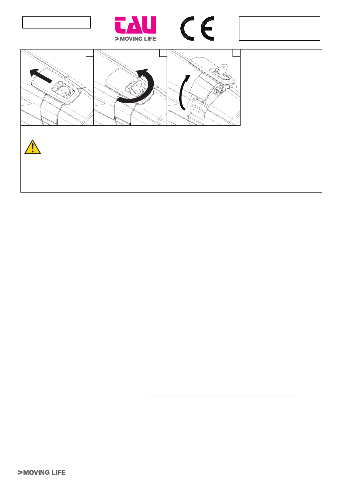
1
GUIDA UTENTE - USER GUIDE - FÜHRER BENUTZER - GUIDE USAGER - GUÍA USUARIO
ISTRUZIONI ED AVVERTENZE DESTINATE ALL’UTILIZZATORE DELL’AUTOMAZIONE
COMPLIMENTI per aver scelto per la vostra automazione un prodotto Tau!
Tau S.r.l. produce componenti per l’automazione di cancelli, porte, barriere, serramenti: motoriduttori, centrali di comando, radiocomandi, lampeggianti,
fotocellule e accessori.
I prodotti Tau sono realizzati solo con materiali e lavorazioni di qualità e, come azienda, siamo alla costante ricerca di soluzioni innovative che
semplifichino sempre più l’utilizzo delle nostre apparecchiature, curate sotto ogni aspetto (tecnico, estetico ed ergonomico): nella grande gamma Tau
il vostro installatore può scegliere il prodotto che meglio soddisfa le vostre esigenze.
Tau però non produce la vostra automazione che, invece, è il risultato di un’opera di analisi, di valutazione, di scelta dei materiali e realizzazione
dell’impianto eseguita dal vostro installatore di fiducia.
Ogni automazione, pertanto, è unica e solo il vostro installatore può eseguire un impianto secondo le vostre esigenze (in quanto dotato dell’esperienza
e della professionalità necessarie), sicuro ed affidabile nel tempo; e soprattutto a regola d’arte, rispondente cioè alle normative in vigore.
Un impianto di automazione è una bella comodità, oltre che un valido sistema di sicurezza e, con poche, semplici attenzioni, è destinato a durare
negli anni.
DESCRIZIONE
L’automazione ARM200 per cancelli a battente è un attuatore elettromeccanico irreversibile che trasmette il movimento all’anta tramite un sistema a
vite senza fine.
L’attuatore è disponibile in più versioni in 12 Vdc e in 230 Vac.
Il sistema irreversibile garantisce il blocco meccanico dell’anta quando il motore non è in funzione. Un comodo e sicuro sistema di sblocco con chiave
personalizzata permette la movimentazione manuale dell’anta in caso di disservizio o di mancanza di alimentazione.
Anche se l’automazione in vostro possesso soddisfa il livello di sicurezza richiesto dalle normative, questo non esclude l’esistenza di un “rischio residuo”,
cioè la possibilità che si possano generare situazioni di pericolo, dovute ad un utilizzo incosciente e/o errato. Per questo motivo riportiamo alcuni consigli
sui comportamenti da tenere per evitare ogni inconveniente:
- Al primo utilizzo: chiedete al vostro installatore di spiegarvi l’origine dei rischi residui e leggete il presente manuale di istruzioni ed avvertenze per
l’utilizzatore consegnatovi dall’installatore. Conservate il manuale per qualsiasi problema futuro e ricordatevi di consegnarlo ad un eventuale nuovo
proprietario dell’impianto.
- L’impianto di automazione esegue fedelmente i vostri comandi: un uso incosciente e/o improprio può divenire pericoloso. Evitate quindi di
azionare l’automazione quando nel suo raggio d’azione si trovino persone, animali e/o cose.
- NON È UN GIOCO! Fate in modo che i bambini non giochino in prossimità dell’impianto e tenete i telecomandi fuori della loro portata.
- Anomalie: ad ogni comportamento anomalo dell’impianto, togliete l’alimentazione elettrica all’automazione ed eseguite lo sblocco manuale (come
da figura). Evitate qualsiasi intervento personale e chiamate il vostro installatore: una volta sbloccato, l’impianto funzionerà manualmente come
prima dell’installazione.
- Manutenzione: per durare nel tempo e funzionare in completa sicurezza, come qualsiasi altro macchinario, l’impianto necessita di una periodica
manutenzione. Stabilite insieme al vostro installatore i tempi di tale manutenzione. Tau consiglia un intervento ogni 6 mesi per un normale uso
domestico, che può variare in funzione dell’intensità d’uso (sempre ogni 3000 cicli di lavoro).
N.B. Qualsiasi tipo di intervento (controllo, manutenzione e/o riparazione) deve essere eseguito solo da personale qualificato.
- Non modificare l’impianto, nè i relativi parametri di programmazione e di regolazione: la responsabilità è dell’installatore.
N.B. Il collaudo finale, le manutenzioni periodiche e le eventuali riparazioni devono essere documentate (negli appositi spazi) da chi le esegue
e i documenti conservati dal proprietario dell’impianto (IN CASO DI MANCATA DOCUMENTAZIONE LA GARANZIA DECADE).
- Smaltimento: al termine della vita dell’impianto assicuratevi che lo smantellamento venga eseguito da personale qualificato e che i materiali
vengano riciclati o smaltiti secondo le norme valide a livello locale.
La manovra manuale deve essere eseguita SOLO a porta ferma e DOPO aver tolto l’alimentazione alla centrale elettrica.
Nota: se il vostro impianto è dotato di un telecomando che dopo qualche tempo vi sembra funzionare peggio, oppure non funzionare affato, potrebbe
semplicemente dipendere dall’esaurimento della pila (a seconda del tipo, possono trascorrere diversi mesi fino a 2/3 anni). Ve ne potete accorgere
dal fatto che la spia di conferma della trasmissione è debole, oppure si accende solo per un breve istante. Prima di rivolgervi all’installatore provate a
scambiare la pila con quella di un altro trasmettitore eventualmente funzionante: se questa fosse la causa dell’anomalia, sarà sufficiente sostituire la pila
con un’altra dello stesso tipo.
Nel caso voleste aggiungere nella vostra casa un nuovo tipo di automazione, rivolgendovi allo stesso installatore e alla Tau vi garantirete, oltre che la
consulenza di uno specialista e i prodotti più evoluti del mercato, il migliore funzionamento e la massima compatibilità delle automazioni.
Vi ringraziamo per aver letto queste raccomandazioni, e vi auguriamo la massima soddisfazione dal vostro nuovo impianto: per ogni tipo di esigenza
rivolgetevi con fiducia al vostro installatore.
- - -- - - - - - - - - - - - - - - - - - - - - - - - - - - - - - - - - - - - - - - - - - - - - - - - - - - - - - - - - - - - - - - - - - - - - - - - - - - - - - - - - - - - - - - - - - - - - -
> ITALIANO
Guida
Utente
SBLOCCO MANUALE
Nel caso si renda necessario movi-
mentare manualmente l’automazione,
per mancanza di alimentazione o dis-
servizio dell’attuatore, agire come di
seguito:
1_ Togliere l’alimentazione elettrica
agendo sull’interruttore differen-
ziale (anche in caso di mancanza
di alimentazione).
2_ Far scorrere il cappuccio protettivo,
fig.1;
3_ Inserire la chiave nello sblocco e
ruotarla in senso antiorario, fig.2.
4_ Ruotare, come mostrato in fig.3, la leva di sblocco verso l'alto per sbloccare l'attuatore.
5_ Effettuare manualmente la manovra di apertura o di chiusura dell’anta.
Nota bene: Per mantenere l’attuatore in funziona-mento manuale è assolutamente necessario lasciare il dispositivo di sblocco
nella posizione attuale e l’impianto disalimentato.
RIPRISTINO DEL FUNZIONAMENTO NORMALE
Per ripristinare le condizioni di funzionamento normale agire come di seguito:
1_ Ruotare la leva di sblocco verso il basso.
2_ Ruotare di 90° la chiave di sblocco ed estrarla.
3_ Richiudere il coperchietto di protezione.
4_ Alimentare l’impianto ed eseguire alcune manovre per verificare il corretto ripristino di tutte le funzioni dell’automazione.
1 2 3

2
GUIDA UTENTE - USER GUIDE - FÜHRER BENUTZER - GUIDE USAGER - GUÍA USUARIO
INSTRUCTIONS AND WARNINGS FOR AUTOMATIC SYSTEM USERS
CONGRATULATIONS on choosing a Tau product for your automation system!
Tau S.r.l. produces components for automatic gates, doors, barriers and shutters. These include gear motors, control units, radio control devices, flashing lights,
photocells and accessories.
Tau products are exclusively made with top quality materials and processes and, as a company, we constantly research and develop innovative solutions in order
to make our equipment increasingly easier to use. We also pay great attention to all details (technology, appearance and ergonomics). The extensive Tau range
makes it possible for your fitter to choose the product which best meets your requirements.
Tau, however, does not produce your automated system as this is the outcome of a process of analysis, evaluation, choice of materials and installation performed
by your fitter.
Each automated system is unique, therefore, and only your fitter has the experience and professionalism required to create a system that is tailor-made to your
requirements, featuring long-term safety and reliability, and, above all, professionally installed and compliant with current regulations.
An automated system is handy to have as well as being a valid security system. Just a few, simple operations are required to ensure it lasts for years.
DESCRIPTION
The ARM200 automated system for swing gates is an electro-mechanical non-reversing actuator that transmits motion to the leaf via a worm screw
system.
The actuator is available in more versions in 12 Vdc and 230 Vac.
The non-reversing system ensures the leaf is mechanically locked when the motor is not operating. A convenient and safe release system with customised
key makes it possible to manually move the leaf in the event of a malfunction or of a power failure.
Even if your automated system satisfies regulatory safety standards, this does not eliminate “residue risks”, that is, the possibility of dangerous situations being
generated, usually due to irresponsible and/or incorrect use. For this reason we would like to give you some suggestions on how to avoid these risks:
- Before using the system for the first time: ask your fitter to explain how residue risks can arise and read the instructions and warnings in the user
handbook that your fitter will have given you. Keep this manual for future use and, if you should ever sell your automated system, hand it over to the new
owner.
- Your automated system carries out your commands to the letter: irresponsible and/or incorrect use may cause it to become dangerous. Do not use the
system if people, animals and/or objects enter its operating area.
- IT IS NOT A TOY! Make sure children do not play near the system and keep the remote control device out of their reach.
- Faults: If you notice any abnormal behaviour, disconnect the system from the power supply immediately and perform the manual release operation (see
figure). Do not attempt to repair the door but call in your fitter: the system will operate manually as it did before installation.
- Maintenance: to ensure long life and totally safe operation, the system required routine maintenance, just like any other piece of machinery. Establish
maintenance times together with your fitter. Tau recommends a frequency of 6 months for normal domestic installations but this may vary depending on the
intensity of use (always every 3000 work cycles).
N.B.: All controls, maintenance work and/or repairs may only be carried out by qualified personnel.
- Do not modify the plant or the relative programming and adjustment parameters: your fitter will see to that.
N.B. Final testing, routine maintenance and any repairs must be documented by the fitter (in the relative spaces) and such documents kept by the
owner of the system (IF THE DOCUMENTS ARE NOT PRODUCED, THE WARRANTY WILL EXPIRE).
- Disposal: At the end of system life, make sure that it is demolished by qualified personnel and that the materials are recycled or disposed of according to
local regulations.
The manual manoeuvre must ONLY be done with the door stopped and AFTER disconnecting power from the electrical control unit.
N.B.: if your remote control unit (if supplied) starts working badly after a time, or does not work at all, the batteries may be flat (they can last from several months
to 2/3 years depending on what type is used). This can be seen from the fact that the transmission confirmation LED gets dimmer or only turns on for brief
moments. Before contacting your fitter, try exchanging the battery with one from a good transmitter: if this is the reason for the fault, simply replace the battery
with another one of the same type.
If you wish to add a new automated system to your house, contact your fitter and we at Tau to have the advice of a specialist, the most developed products on
the market, best operation and maximum automation compatibility.
Thank you for reading these suggestions and we trust you are fully satisfied with your new system: please contact your fitter for any further requirements.
> ENGLISH
User
Guide
MANUAL RELEASE
If the automated system needs to be
moved manually due to a power lack or
to an operator malfunction, proceed as
follows:
1_ Cut power by means of the safety
circuit breaker (even in the event of
a power lack).
2_ Slide the protective cap, fig.16;
3_ Insert the key and turn it 90°,
fig.17.
4_ As shown in fig.18, rotate the
release lever upward in order to
release the actuator.
5_ Open or close the leaf manually.
Note: To hold the operator in manual operation the release device should be left in its current positions and the system should
be without power.
RESTORING NORMAL OPERATION
To restore normal operating conditions, proceed as follows:
1_ Lock the release lever by rotating it downward.
2_ Turn 90° the release key and remove it.
3_ Close the protection cover.
4_ Power up the system and perform some movements in order to check the correct restoring of every function of the automated system.
1 2 3
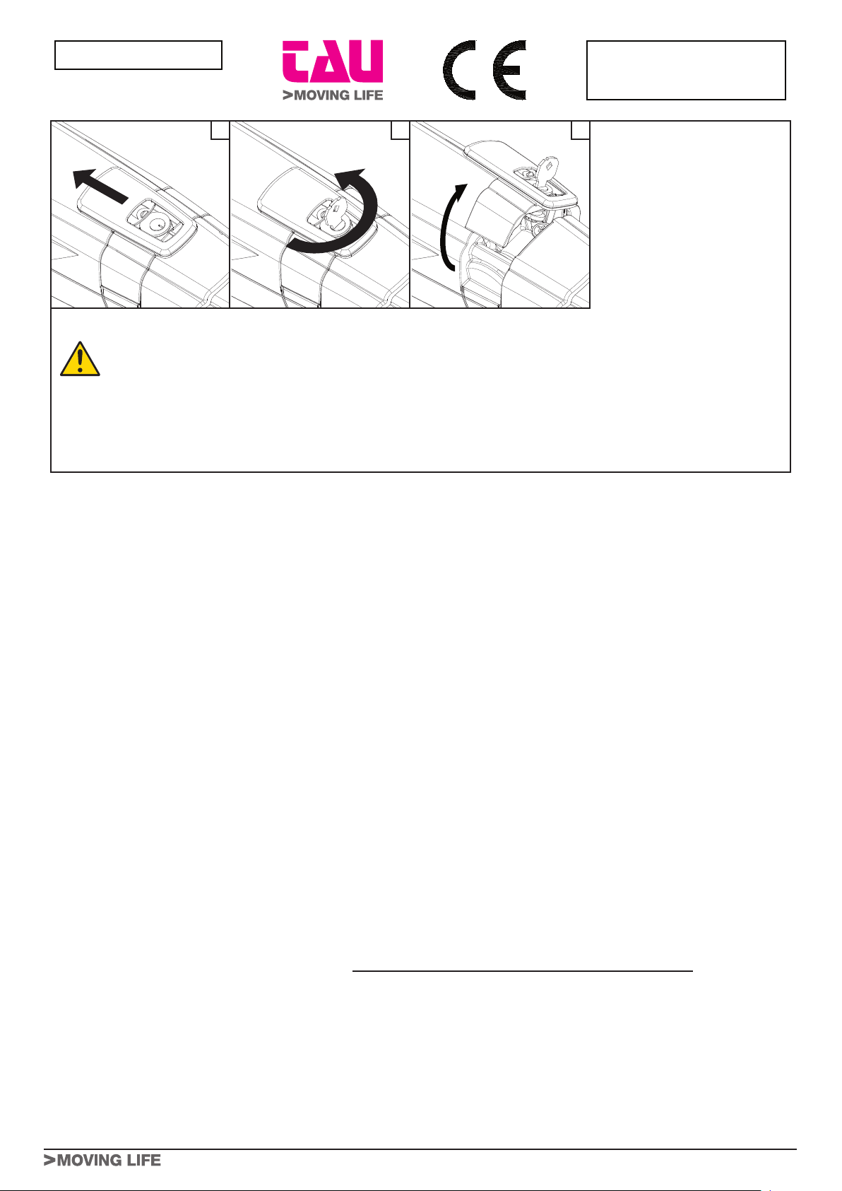
3
GUIDA UTENTE - USER GUIDE - FÜHRER BENUTZER - GUIDE USAGER - GUÍA USUARIO
ANWEISUNGEN UND HINWEISE FÜR DEN BENUTZER DER AUTOMATISIERUNG
WIR GRATULIEREN IHNEN zur Wahl eines Tau Produktes für Ihre Automatisierung!
Tau S.r.l. stellt Komponenten für die Automatisierung von Toren, Türen, Schranken und Fenstern her: Getriebemotoren, Steuerzentralen, Funksteuerungen, Blinkleuchten,
Fotozellen und Zubehör.
Die Tau Produkte werden nur mit Materialien und Bearbeitungen hoher Qualität hergestellt, und unsere Firma ist auf der ständigen Suche nach innovativen Lösungen, mit denen
die Benutzung unserer Apparaturen, die in jeder Hinsicht (Technik, Aussehen und Ergonomie) besonders gepflegt sind, immer einfacher wird: unter dem großen Tau Sortiment
kann Ihr Installateur das Produkt auswählen, das Ihrem Bedarf am besten entspricht.
Tau ist aber nicht der Hersteller Ihrer Automatisierung, die dagegen das Ergebnis des Werks Ihres Vertrauensinstallateurs ist, der sich mit den notwendigen Untersuchungen und
Bewertungen, der Wahl der Materialien und der Verwirklichung die Anlage beschäftigen wird.
Jede Automatisierung ist daher einzigartig und nur Ihr Installateur kann eine Anlage ausführen, die Ihrem Bedarf entspricht (er besitzt die notwendige Erfahrung und Professionalität),
die sicher und auf Zeit zuverlässig und vor allem fachgerecht ist und mit den gültigen Vorschriften übereinstimmt.
Eine Automatisierungsanlage ist etwas wirklich bequemes, aber auch ein gutes Sicherheitssystem, und mit ein paar einfachen Maßnahmen wird sie jahrelang dauern.
BESCHREIBUNG
Die Automation ARM200 für Flügeltore ist ein irreversibler elektromechanischer Antrieb, der über ein Schneckensystem die Bewegung auf den Flügel überträgt.
Der Antrieb ist in mehreren Versionen erhältlich in 12 Vdc und 230 Vac.
Das irreversible System gewährleistet die mechanische Verriegelung des Flügels, wenn der Motor nicht in Betrieb ist. Ein praktisches und sicheres Freigabesystem mit
individuellem Schlüssel ermöglicht die manuelle Bewegung des Flügels bei Betriebsstörungen oder Stromausfall.
Auch wenn Ihre Automatisierung dem Sicherheitsniveau entspricht, das von den Vorschriften gefordert wird, schließt dies das Vorhandensein eines „Restrisikos” nicht aus, bzw.
der Möglichkeit, dass Gefahren aufgrund eines fahrlässigen und/oder falschen Gebrauchs erzeugt werden können. Aus diesem Grund geben wir hier einige Verhaltensweisen
an, um diese möglichen Restrisiken zu vermeiden:
- Bei der ersten Benutzung: bitten Sie Ihren Installateur, Ihnen den Ursprung der Restrisiken zu erklären, und lesen Sie die vorliegenden Anweisungen und Hinweise für
den Benutzer, die Ihnen vom Installateur übergeben werden. Bewahren Sie die Anleitung für zukünftige Probleme auf, und übergeben Sie diese ggf. dem neuen Besitzer
der Anlage.
- Die Automatisierungsanlage folgt getreu Ihren Befehlen: ein fahrlässiger und/oder unsachgemäßer Gebrauch kann gefährlich sein. Betätigen Sie daher die
Automatisierung nicht, wenn sich Personen, Tiere und/oder Gegenstände in ihrem Aktionskreis befinden.
- SIE IST KEIN SPIEL! Lassen Sie Kinder nicht in der Nähe der Anlage spielen und halten Sie die Fernbedienungen außer deren Reichweite.
- Störungen: schalten Sie bei jedem ungewöhnlichen Verhalten der Anlage die Stromversorgung zur Automatisierung ab und entriegeln Sie von Hand (siehe Abbildung).
Vermeiden Sie jeden persönlichen Eingriff und rufen Sie Ihren Installateur: nach dem Entriegeln wird die Anlage von Hand funktionieren, wie vor der Installation.
- Wartung: um zu dauern und ganz sicher zu funktionieren, bedarf die Anlage wie jede andere Maschine einer periodischen Wartung. Legen Sie die Wartungszeiten
zusammen mit Ihrem Installateur fest. Tau empfiehlt für den normalen Hausgebrauch eine Wartung alle 6 Monate, was je nach Gebrauchshäufigkeit unterschiedlich sein
kann (immer ungefähr 3000 Arbeitszyklen).
N.B.: Eingriffe (Kontrolle, Wartung und/oder Reparatur) dürfen nur von Fachpersonal ausgeführt werden.
- Anlage und programmierte und eingestellte Parameter nicht ändern, das ist Aufgabe des Installateurs.
N.B.: Endprüfung, periodische Wartungsarbeiten und eventuelle Reparaturen müssen von dem, der sie ausführt, belegt sein (in den dazu bestimmten Feldern);
diese Unterlagen muss der Besitzer der Anlage aufbewahren (DIE GARANTIE WIRD UNGÜLTIG, FALLS DIE DOKUMENTATION FEHLT).
- Entsorgung: stellen Sie am Ende der Lebensdauer der Anlage sicher, dass die Entsorgung durch Fachpersonal erfolgt und dass die Materialien nach den örtlich gültigen
Vorschriften recycled oder entsorgt werden.
Die manuelle Bewegung darf AUSSCHLIESSLICH bei stehendem Tor und NACH Abschalten der Versorgung zur Steuerung ausgeführt werden.
Anmerkung: wenn eine Fernbedienung zu Ihrer Anlage gehört, die nach einer bestimmten Zeit schlechter oder gar nicht funktioniert, sollten Sie die Batterie kontrollieren, die
ganz einfach leer sein könnte (je nach Typ, kann die Batterie mehrere Monate bis 2-3 Jahre dauern). Sie können das am Leuchtmelder bemerken, der die Übertragung bestätigt
und nur schwach oder ganz kurz aufleuchten wird. Tauschen Sie die Batterie mit der eines anderen, funktionierenden Senders aus, bevor Sie sich an den Installateur wenden:
falls die Ursache der Betriebsstörung eine leere Batterie sein sollte, genügt es, diese mit einer anderen gleichen Typs zu ersetzen.
Falls Sie Ihrem Haus eine weitere neue Automatisierung hinzufügen wollen, werden Sie sich bei Ihrem Installateur und bei Tau neben der Beratung eines Fachmanns die
fortgeschrittensten Produkte garantieren, die es auf dem Markt gibt, mit bestem Betrieb und maximaler Kompatibiltät der Automatisierungen.
Wir danken Ihnen, dass Sie diese Hinweise gelesen haben und wünschen Ihnen volle Zufriedenheit mit Ihrer neuen Anlage. Wenden Sie sich für jeden Bedarf vertrauensvoll
an Ihren Installateur.
> DEUTSCH
Führer
Benutzer
MANUELLE ENTRIEGELUNG
Sollte die manuelle Bewegung
der Automation erforderlich sein
aufgrund von Stromausfall oder
Betriebsstörungen des Antriebs,
sind die nachfolgenden Schritte
auszuführen:
1_ Mit Hilfe des Differentialschalters
(auch bei Stromausfall) die Strom-
versorgung unterbrechen.
2_ Die Schutzhaube - Abb.16 - gleiten
lassen.
3_ Den Schlüssel einstecken und um
90° drehen, Abb.17.
4_ Den Entriegelungshebel wie in Abb. 18 gezeigt nach oben drehen, um den Antrieb zu entriegeln.
5_ Den Vorgang zum Öffnen oder Schließen des Flügels manuell ausführen.
Anmerkung: Zur Beibehaltung des manuellen Betriebs des Antriebs muss die Freigabevorrichtung unbedingt in ihrer aktuellen
Position gelassen werden und die Stromzufuhr zur Anlage muss weiterhin unterbrochen bleiben.
WIEDERHERSTELLUNG DES NORMALBETRIEBS
Zur Wiederherstellung der normalen Betriebsbedingungen sind die nachfolgenden Schritte auszuführen:
1_ Den Entriegelungshebel nach unten schließen.
2_ Den Freigabeschlüssel um 90° drehen und herausziehen.
3_ Den Schutzdeckel verschließen.
4_ Die Anlage mit Strom versorgen und einige Vorgänge ausführen, um die korrekte Wiederherstellung aller Funktionen der Automation zu prüfen.
1 2 3
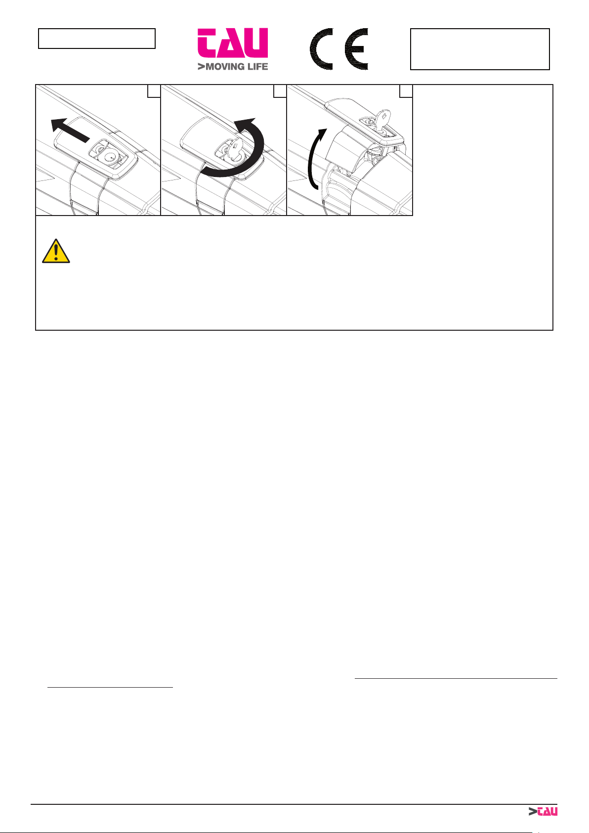
4
GUIDA UTENTE - USER GUIDE - FÜHRER BENUTZER - GUIDE USAGER - GUÍA USUARIO
INSTRUCTIONS ET RECOMMANDATIONS DESTINÉES À L’UTILISATEUR DE L’AUTOMATISATION
FÉLICITATIONS pour avoir choisi pour votre automatisation un produit Tau !
Tau S.r.l. produit des composants pour l’automatisation de portails, portes, barrières, volets : opérateurs, logiques de commande, radiocommandes, clignotants, photocellules
et accessoires.
Les produits Tau sont réalisés exclusivement avec des matériaux et des usinages de qualité et en tant qu’entreprise, nous sommes à la recherche constante de solutions
innovantes qui simplifient de plus en plus l’utilisation de nos appareils, soignés sur tous les plans (technique, esthétique et ergonomique) : dans la vaste gamme Tau, votre
installateur peut choisir le produit qui satisfera au mieux vos exigences.
Tau toutefois ne produit pas votre automatisation qui est, en fait, le résultat d’un travail d’analyse, d’évaluation, de choix des matériaux et de réalisation de l’installation effectué
par votre installateur de confiance.
Chaque automatisation, par conséquent, est unique et seul votre installateur peut réaliser une installation suivant vos exigences (dans la mesure où il est doté de l’expérience et
de la qualification professionnelle nécessaire), sûre et fiable dans le temps et, surtout, effectuée dans les règles de l’art, c’est-à-dire conforme aux normes en vigueur.
Une installation d’automatisation est d’une grande commodité, en plus de représenter un système de sécurité et, avec un minimum d’attentions, elle est destinée à durer des
années.
DESCRIPTION
L’automatisme ARM200 pour portails battants est un opérateur électromécanique irréversible qui transmet le mouvement au vantail par l’intermédiaire d’un système à vis sans
fin.
L’opérateur est disponible en plusieurs versions en 12 Vdc et 230 Vac.
Le système irréversible garantit le verrouillage mécanique du vantail quand le moteur n’est pas en fonction. Un système pratique et sûr de déblocage à clé personnalisée permet
l’actionnement manuel du vantail en cas de dysfonctionnement ou de coupure de courant.
Même si l’automatisme en votre possession satisfait le niveau de sécurité requis par les normes, cela n’exclut pas l’existence d’un “risque résiduel”, c’est-à-dire la possibilité que
des situations de danger puissent se vérifier, à cause d’une utilisation non raisonnable et/ou erronée. Pour cette raison, nous donnons quelques conseils sur les comportements
à suivre pour éviter tout inconvénient :
- À la première utilisation : demandez à votre installateur de vous expliquer l’origine des risques résiduels et lisez ce manuel d’instructions et de recommandations
pour l’utilisateur qui vous a été remis par l’installateur. Conservez le manuel pour tout problème futur et n’oubliez pas de le remettre à l’éventuel nouveau propriétaire de
l’installation.
- L’installation d’automatisation exécute fidèlement vos commandes : une utilisation non raisonnable et/ou impropre peut devenir dangereuse. Évitez par conséquent
d’actionner l’automatisme quand des personnes, des animaux ou des objets se trouvent dans son rayon d’action.
- CE N’EST PAS UN JEU ! Faites en sorte que les enfants ne jouent pas à proximité de l’installation et conservez les télécommandes hors de leur portée.
- Anomalies: à tout comportement anormal de l’installation, coupez l’alimentation électrique de l’automatisme et effectuez le déblocage manuel (comme sur la figure). Évitez
toute intervention personnelle et contactez votre installateur : une fois débloquée, l’installation fonctionnera manuellement, comme avant l’automatisation.
- Maintenance : pour durer dans le temps et fonctionner en toute sécurité, comme toute autre machine, l’installation a besoin d’une maintenance périodique. Établissez avec
votre installateur un plan de maintenance. Tau conseille une intervention tous les 6 mois pour un usage domestique normal qui peut varier suivant l’intensité d’utilisation
(toujours tous les 3000 cycles de travail).
N.B. N’importe quel type d’intervention (contrôle, maintenance et/ou réparation) doit être effectué uniquement par du personnel qualifié.
- Ne pas modifier l’installation ni les paramètres de programmation et de réglage : la responsabilité en incombe à l’installateur.
N.B. l’essai de fonctionnement final, les maintenances périodiques et les éventuelles réparations doivent être documentées (dans les espaces prévus à cet effet)
par qui les exécute et les documents doivent être conservés par le propriétaire de l’installation (EN CASE DE NON-PRÉSENTATION DE LA DOCUMENTATION,
LA GARANTIE N’EST PLUS VALABLE).
- Démantèlement : à la fin de la vie de l’installation, assurez-vous que le démantèlement soit effectué par du personnel qualifié et que les matériaux soient recyclés ou mis
au rebut suivant les normes en vigueur au niveau local.
La manœuvre manuelle doit être exécutée UNIQUEMENT avec la porte fermée et APRÈS avoir coupé l’alimentation de l’armoire électrique.
Note : si votre installation est munie d’une télécommande qui au bout de quelques temps semble moins bien fonctionner ou ne plus fonctionner du tout, cela peut dépendre tout
simplement de la pile (suivant le type sa durée est de plusieurs mois jusqu’à 2/3 ans). Vous pouvez vous en rendre compte à travers le fait que le voyant de confirmation de la
transmission est faible ou bien, s’il ne s’allume qu’un bref instant. Avant de vous adresser à l’installateur, essayez d’échanger la pile avec celle d’un autre émetteur qui fonctionne
correctement : si la cause de l’anomalie est celle-ci, il suffira de remplacer la pile par une autre du même type.
Si vous désirez ajouter un nouveau type d’automatisme dans votre habitation, adressez-vous au même installateur et à Tau ; en plus du conseil d’un spécialiste, vous aurez ainsi
la garantie des produits les plus évolués sur le marché, du meilleur fonctionnement et du maximum de compatibilité entre les automatismes.
Nous vous remercions d’avoir lu ces recommandations et nous espérons que votre nouvelle installation vous donnera toute satisfaction : pour tout type d’exigence, adressez-
vous en toute confiance à votre installateur.
> FRANÇAIS
Guide
Usager
DÉBLOCAGE MANUEL
Si nécessaire, actionner manuellement
l’automatisme; en cas de coupure de
courant ou de dysfonctionnement de
l’opérateur, agir comme suit:
1_ Couper le courant en agissant sur
l’interrupteur différentiel (même si
le courant est déjà coupé).
2_ Faire coulisser le capuchon de
protection, fig.16;
3_ Introduire la clé et la tourner de
90°, fig.17.
4_ Tourner le levier de débrayage
vers le haut, comme indiqué sur la
fig.18, pour débrayer le vérin.
5_ Effectuer manuellement la manœuvre d’ouverture ou de fermeture du vantail.
Note: pour maintenir l’opérateur en fonctionnement manuel, il est absolument nécessaire de laisser le dispositif de déblocage
dans la position actuelle et l’installation hors tension.
RÉTABLISSEMENT DU FONCTIONNEMENT NORMAL
Pour rétablir les conditions de fonctionnement normal, agir comme suit:
1_ Refermer le levier de débrayage vers le bas.
2_ Tourner de 90° la clé de déblocage et l’extraire.
3_ Refermer le couvercle de protection.
4_ Alimenter l’installation et effectuer quelques manœuvres pour vérifier le rétablissement de toutes les fonctions de l’automatisme.
1 2 3

15
ARM200 Series
- - -- - - - - - - - - - - - - - - - - - - - - - - - - - - - - - - - - - - - - - - - - - - - - - - - - - - - - - - - - - - - - - - - - - - - - - - - - - - - - - - - - - - - - - - - - - - - - -
g. 1
g. 2
g. 3
ARM200 Series DISEGNI - DRAWINGS - ZEICHNEN - PROJETS - DIBUJOS
1
2
6
5
3
4
TYPE A B
ARM225 -
ARM225BENC 811 mm 783 mm
ARM250 -
ARM250BENC 951 mm 923 mm
ARM270 -
ARM270BENC 1056 mm 1028 mm
1
a
2
74
4
1a
b
f
c
c
d
d
e
7
3
7
3
5
6
ARM200 ARM200BENC
a 4x1,5 mm² 2x2,5 mm² + 3x0,5 mm²
b 3x1,5 mm² 3x1,5 mm²
c 2x0,5 mm² 2x0,5 mm²
d 4x0,5 mm² 4x0,5 mm²
e 3x0,5 mm² 3x0,5 mm²
f 2x1 mm² + 1RG58 2x1 mm² + 1RG58
99 122,5
A
B
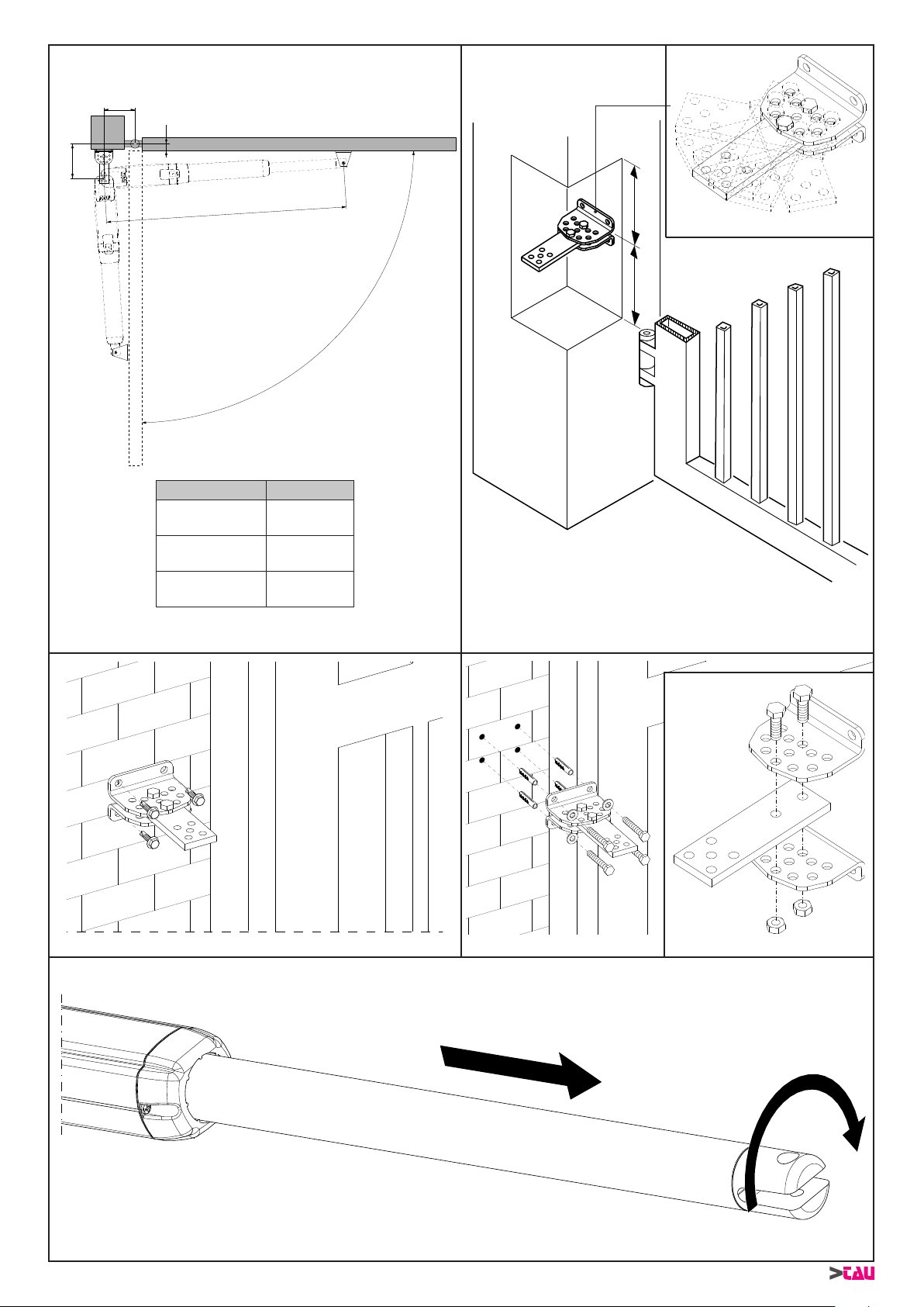
16
ARM200 Series
A
C
X°
B
L
=
=
g. 7g. 6
g. 5A
g. 4
g. 7A
g. 8
12
TYPE L
ARM225 -
ARM225BENC 1080 mm
ARM250 -
ARM250BENC 1360 mm
ARM270 -
ARM270BENC 1570 mm
ARM200 Series DISEGNI - DRAWINGS - ZEICHNEN - PROJETS - DIBUJOS
g. 5
Other manuals for ARM200 Series
4
This manual suits for next models
7
Table of contents
Other tau Gate Opener manuals


Popular Gate Opener manuals by other brands

CAME
CAME FROG series installation manual

Hiland
Hiland SLG5750XAC user manual

Motorline professional
Motorline professional LINCE300 User's and installer's manual

Bauer
Bauer ICARO SMART AC A2000 Installation and user manual

La Toulousaine
La Toulousaine 1033 Installation & connection manual

Global
Global 2200 instruction manual


