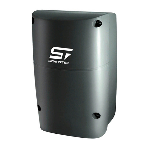
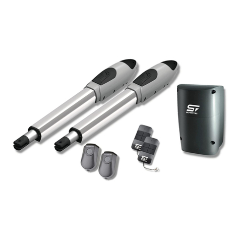
Schartec Porte 300 User manual

Porte 300 Users Manual
Swing Gate Opener
24V DC
for residential use only
Signal Light
Control Box
Push-button
Gate 2
Gate 1

Contents
1. Important Safety Information
2. Product Description and Application
2.1 Application
2.2 Overview
2.3 Parts and components description
2.3.1 Electromechanical gear motors
2.3.2 Control Box
2.3.3 Photocells
2.3.4 Remote Controls (Hand transmitters)
2.3.5 Signal Light
2.3.6 Key Switch
2.3.7 Push-Button
2.3.8 Electric Lock and Stopper-Plate
3. Installation
3.1 Notes on use of the operator
3.1.1 Tools needed for the installation
3.1.2 Operator components and their installation
3.2 Power Supply
3.2.1 Notes on Power Supply
3.3 Installation
3.3.1 Preparation for motors
3.3.2 Motors installation
4. Technical Data
4.1 Porte 300
2

1. Important Safety Information
1.1 Intended Use
The Schartec Porte 300 swing gate opener is intended exclusively for the operation of smooth-running
swinging gates in private, non-commercial areas. The maximum permissible gate size and maximum weight
must not be exceeded. The gate must be easy to open and close by hand. Regional wind loads must be
taken into account when using gate fillings/panels (EN 13241-1). Observe the manufacturer's instructions
regarding the combination of gate and operator. Possible hazards in regards to DIN EN 13241-1 will be
avoided when the installation and assembly is completed according to our specifications. Gate systems
which are located in the public area and are protected by only one protective device, e.g. force limitation,
may only be operated under supervision.
1.2 Unintended use
Continuous operation and use in the commercial sector is not permitted. The operator is not designed for the
use of heavy-duty gates or gates that are larger than the specified permissible size and weight. Use on gates
with inclines or slopes is not permitted.
1.3 Qualification of the fitter/installer
Safe and intended functioning of the mounting and installation can only be ensured when the correct
installation and maintenance is carried out by a competent / knowledgeable company or a competent /
knowledgeable person in accordance with the instructions. A qualified person is, in accordance with EN
12635, a person with appropriate training, knowledge, and experience to correctly safely assemble, test, and
maintain a gate system.
1.4 Safety instructions for installation, maintenance, repair, and dismantling of the gate system
WARNING! Risk of injury due to unexpected gate travel.
The installation, maintenance, repair, and dismantling of the gate system and the gate operator must be
carried out by qualified persons. In the event of failure of the gate system and the gate operator, immediately
commission a qualified person for inspection and/or repair.
1.5 Safety instructions for installation
The qualified person must ensure that the current work safety regulations and the regulations governing the
operation of electrical equipment are followed when performing the installation work. In doing so, the national
guidelines must be observed. Potential hazards in regards to DIN EN 13241-1 are avoided when the
construction and assembly according to our specifications are followed. After completion of the installation,
the installer of the system must be able to declare conformity to DIN EN 13241-1 in accordance with the
scope of application.
1.6 Safety instructions for commissioning and operation
Danger of injury due to damaged components.
Faults with the gate system or incorrectly aligned gate doors can lead to serious injuries! Do not use the gate
system if repairs or adjustments have to be made! Check the entire gate system (hinges, gate bearings,
springs, and mounting hardware for wear and possible damage. Check for rust, corrosion, and cracks.) For
your own safety, have maintenance and repair work carried out by a qualified person only!
For your own safety, have any required maintenance and repair work to the gate done by a qualified person
before you install the gate operator. Only correct installation and maintenance by a competent company or
competent person in accordance with the instructions can ensure the safe and intended functioning. The
qualified person must ensure that the applicable regulations regarding occupational safety and those
governing the operation of electrical devices to be followed when carrying out the installation work. Here, the
national guidelines must be observed. Possible hazards are avoided when the construction and assembly
according to our specifications is carried out. Prior to installation, disable the gates mechanical interlocks,
which are not required for operation with the door operator, or disassemble them completely if necessary.
These include in particular the locking mechanisms of the gate lock. Check that the gate is mechanically
faultless so that it can be easily operated manually and can be opened and closed properly (EN 12604).
3

1.7 Further important information
1.
Please read and follow all safety instructions and installation recommendations.
2.
The gate operator has been designed and manufactured according to local regulations. The installer must
be familiar with local regulations regarding the installation of the swing gate operator.
3.
Unqualified personnel or those not familiar with the safety regulations for the use of automatic gates and
doors may under no circumstances install such a system.
4.
Persons who install and maintain this gate system without observing all applicable safety standards are
liable for damage, injuries, costs, or other claims against persons who have been harmed.
5.
For added security, we recommend using a photoelectric sensor (photocell, included). Although the door
operator has a safety load switch-off, a photocell increases the safety of the system even more.
6.
Make sure the gate is fully open before entering or leaving the driveway.
7.
Make sure that the gate is completely closed while it is still visible. Only then leave the driveway.
8.
Keep hands, loose clothing, and jewelry away from the gate operator.
9.
The power shut-off safety device is intended to prevent serious injury, death, and / or property damage to
immovable obstacles, but not to moving obstacles.
10.
This device is not intended to be used by persons (including children) with limited physical, sensory or
mental capabilities, or lack of experience and knowledge. Children should be supervised to ensure that they
do not play with the device.
11.
Electrical items do not belong in the household waste but must be disposed of properly. Check with
your local authorities, city, or retailer.
12.
If the power cord is damaged, it must be replaced by the manufacturer, its customer service, or a
similarly qualified person to avoid danger.
ATTENTION: Important safety instructions. For the safety of people, it is important to follow all instructions.
Keep this manual.
Do not let children play with the gate operator. Keep the radio controlled remotes away from children. Make
sure that you, bystanders, and children are completely away from the swinging gate until it is completely
opened or closed.
Be careful when manually unlocking the gate operators.
Periodic testing of the equipment (every 6 months), in particular the testing of cables, springs and brackets
for signs of wear, damage or inequality, is necessary. Do not use the gate operator when repair or adjustment
is necessary, as installation failure or improperly balanced gate may result in personal injury.
Monthly testing of safety load switch-off -- if the motor continues to run when the door edge runs into a 50
mm high object. If necessary, adjust and check, as an incorrect setting can be dangerous.
For information on how to engage the manual release, refer to the manual (pg. 24).
For information about adjusting the safety load switch-off, refer to the control box manual.
Disconnect the power supply plug when cleaning or performing any other maintenance.
The installation instructions provide details on how to install the operator and the components it contains.
4

C D
E
2.3 Description of the components
This swing gate operator kit contains components A, B, C, D, H and K.
All other components are available as optional accessories.
A) 2 Motors incl. brackets
B) 2 Manual release keys
C) Photocell
D) 2 Pcs. Remote controls
E) Key switch
F) Interior push-button
G) Signal light
H) Control box
I) Electric lock
J) Stopper plate
K) Screws, bolts, and nuts
Figure 2
2. Product description and application
F
G H
I J
K
Figure 1
2.1 Application
This gate operator is suitable for private entrance gates with 2-leafe swinging gates. The power supply
for commissioning the system is 230 V. For manual operation of the swing gate, the two motors must be unlocked
with the enclosed key.
2.2 Overview
The following graphic shows an example installation.
I
J
F
E
C
H
G
A
A
A
B
5

Figure 3
Figure 4
Figure 5
Figure 6
TX
RX
Porte 300
2.3.1 Electromechanical geared motors
The swing gate operators consist of a 24 V DC motor and a
worm gear. The motors are attached to the gate and pillar
with front and rear brackets. The manual release keys are
required for manual unlocking.
2.3.2 Control Box
The control box consists of a motherboard, a radio receiver and
a transformer. With the help of the control, all functions of the
swing gate operator are configurable. Furthermore, there are
terminals on the motherboard for connecting various
accessories.
2.3.3 Photocell
The photocell is mounted on a exteriorly on a flat surface and
connected to the control box by cables. The transmitter and
receiver visually detect obstacles and automatically reverse the
swing gate if the beam is broken.
2.3.4 Remote contol
Press button "A" to open both wings.
Press key "B" to open one wing (pedestrian pass-through).
Manual release keys
A B
6

Figure 7
Figure 8
Figure 9
3.1 Notes on use of the operator
The Porte 300 swing gate operator is designed for a maximum gate weight of 300 kg (per leaf) and a
maximum gate width of 3 meters (per leaf). The opening angle is up to 110°. These maximum values must
never be exceeded.
3. Installation:
Figure 10
2.3.5 Signaling light
The signal light is connected by a 2-wire cable to the control
box of the swing gate operator. The lamp blinks to signal to
pedestrians that the swing gate operator is in motion.
2.3.6 Key Switch
The key switch is used to operate the swing gate operator with
the turn of a key. It's surface mounted and two keys are
included in the delivery.
2.3.7 Push-button
The interior push-button is used to operate the swing gate
operator from inside the comfort of your garage or home
instead of having to use the remote control. It's surface
mounted and connected by a 2-wire cable to the control box of
the swing gate operator.
2.3.8 Electrick Lock and Stopper Plate
The electric lock with the stopper plate is used to lock your
swing gate in places when closed and thus protects the
gearbox in the motors (especially useful for locations with high
wind). The electric lock is recommended from a door leaf width
of 1.5 m and up.
7

Figure 11
3.1.1 Tools needed for Installation
Please make sure that the tools listed below are available for installation.
3.1.2 Operator components and their installation
Figure 12 shows an example installation with cable management including all possible components. Cables
for accessories are not included.
Figure 12
1.
3.2 Mains Connection (Power Supply)
The mains connection may only be carried out by a qualified person. The connection of the control box is via a 3-
wire cable. Carefully read the assembly instructions for the gate operator before proceeding. Make sure that the
cables are properly layed and and properly inserted to prevent cable breakage. The arrangement of the
accessories should therefore be predetermined.
3.2.1 Note on the power supply connection
2.
The electrical installation and connections for the gate operator may only be carried out by a qualified electrician.
The supply line for the gate operator must be equipped with an over-voltage fuse. Before all electrical work, the
system must be de-energised. Safeguard the system against being switched on again without authorization.
8

Check the following before installation:
Figure 13
Figure 14 (Aerial View)
3.3 Installation
3.3.1 Preparations for the motor installation
The swing gate operator must not be used with defective or sluggish gates. Make sure your door has been
serviced and properly adjusted by a knowledgeable person or professional before installation. The operator is not
intended to compensate for an already defective gate.
8) Make sure that there is enough space when opening the gate leaves.
Porte 300
Porte 300
1) Make sure that the gate weight and gate width do not exceed the specified maximum values of the
operator.
2) Make sure that the gate construction is designed for the forces of the operator.
3) Make sure the gate leaves open and close without friction, scraping, or dragging.
4) Make sure that both gate leaves are balanced and in a horizontal plane.
5) Make sure that the surfaces and the leaves are designed for engine torque.
6) Make sure that the transmitter and receiver of the photocell are mounted on a level surface and are in
proper alignment so that they are in contact with each other.
7) Check the dimensions listed below.
Min
150 mm
150 mm (max)
9

Figure 17
Figure 15 (Aerial View)
10) Use the opening angle of the gate to determine the correct installation dimensions (see also Figure 17)
11) "C" value is 139 mm
12) "D" can be easily measured
13) "A" = "C" + "D"
14) The value "B" can be determined by means of "A" and the opening angle of the gate leaf.
Example: If "A" is 160 mm and the opening angle is 100°, then the distance "B" should be about 190 mm.
** Please make sure that the dimensions "B" and "A" on both sides are approximately equal or as
close to equal to ensure a smooth running of the gate leaves and to protect the motors.
9) If the gate opens to the outside, leave a distance of 70 mm between the motor pivot point and
the mounting bracket.
Porte 300
Porte 300 Figure 16 (Aerial View)
Min
70 mm
10

Figure 18
Figure 19
3.3.2 Installation of the Motors
1) Choose the correct mounting position of the motors.
2) Check that the mounting surfaces for the brackets are level.
3) Insert the cables for the power supply to the motors.
4) Install the motor mounts as shown in Figure 18.
5) Remove the two screws on the engine and remove the cover as shown in Figure 19.
6) Move the gate leaves to the closed position.
7) Refer to the distance "B" as determined in Figure 17. Hold the rear plate of the bracket at the intended mounting
point. Check the distances as shown in Figure 23.
8) If the bracket is at the point where it should be mounted, then mark the four holes. Use an 8 mm drill for this
purpose. Now secure the bracket with screws and washers.
9) Make sure the bracket is completely level.
10) The distance between the rear pivot point and the frontal pivot point is 798 mm. The distance between the
lower edge of front intake to center frontal pivot attachment is 22.5 mm. See Figure 23.
11) Temporarily secure the front bracket to the gate with a clamp. See Figure 24.
139
Figure 20
Figure 21 Figure 22
43 mm
798 mm
22.5 mm
Figure 23 Figure 24
11

Figure 25 Figure 26 Figure 27
Figure 28
Figure 31 Figure 32
Figure 30Figure 29
12) Lift the motor and insert the screw into the front motor mount.
13) Remove the motor cover, loosen the screw and remove the bolt. See Figure 25. Now lift the rear of the motor
and move the gate until the motor can be locked to the rear bracket as shown in Figure 26. Slide the bolt through
the hole provided in the motor and through the rear bracket. Tighten the screw for the bolt. See Figure 27.
14) Tighten the bolt with the nut on the rear bracket, then loosen the nut half a turn to allow the motor arm to
rotate.
15) Now tighten the screw with the nut on the front bracket. Tighten this screw completely.
16) Now connect the motor cables. See Figure 29.
17) Close the motor cover again and tighten the cover screws.
1
1
22
3
3
B
A
Positive (+)
Negative (-)
Motor
18) Manual unlocking of the motor:
19) Turn the round disc on the motor towards "Open". See Figure 31.
20) Slide the cover unlocking forward. See Figure 32.
21) Use the manual release key and turn the release counterclockwise until it stops.
Figure 33
12

4. Technical data
Motor
Gear Type
Peak Force
Motor Travel Length
Power Supply
Max. Working Current
Max. Gate Weight
Max. Gate Width
Operating Temperature
Dimensions
Weight
24 V DC with mechanical unlocking release
Worm Gear
3000 N
350 mm
24 V DC
4 A for max. 10 seconds
300 kg per gate leaf
3 m per gate leaf
-20°C ~ +50°C
844mm * 115mm * 106mm
6.25 kg
Porte 300
13
Other manuals for Porte 300
1
Table of contents
Other Schartec Gate Opener manuals