B&C IC-20 Series User manual
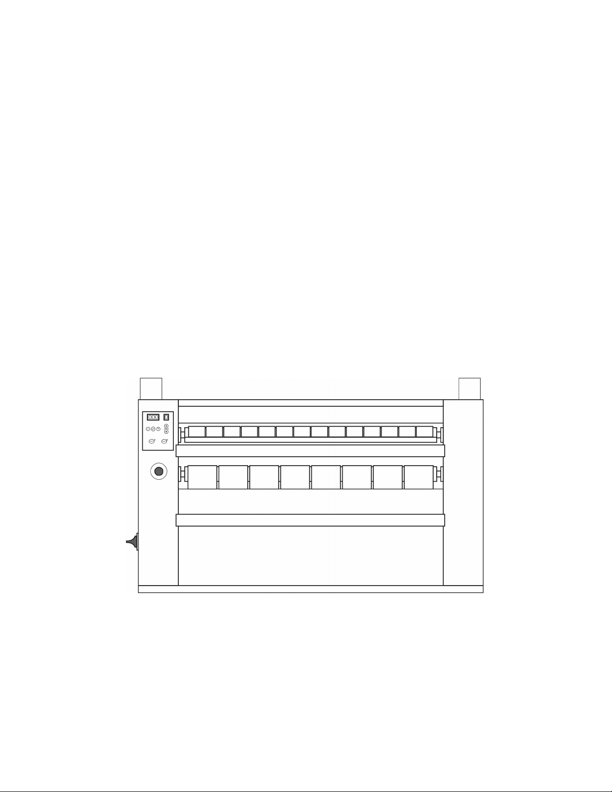
Ironer
IC-20 Series Installation and Operation Manual
August 1, 2020
Revision 1.1

Contents
1 Important Safety Information 1
1.1 FORYOURSAFETY-CAUTION! ............................. 1
2 Important Instructions 2
2.1 BeforeAttemptingRepairs.................................. 2
2.2 PartsOrderingInformation ................................. 3
2.2.1 NameplateLocation ................................. 3
2.3 KeySymbols.......................................... 3
2.4 SafetyInformation ...................................... 3
2.5 Installation and Operational Safety Instructions . . . . . . . . . . . . . . . . . . . . . 5
3 Installation 7
3.1 InstallationNote........................................ 7
3.2 ReceivingInspection ..................................... 7
3.3 ElectricalInstallation ..................................... 8
3.4 GasConnection ........................................ 8
3.4.1 GasSupplyLine ................................... 8
3.4.2 Gas Supply Connection Requirements . . . . . . . . . . . . . . . . . . . . . . . 9
3.5 SteamConnections ...................................... 10
3.6 ExhaustRequirements .................................... 11
3.7 FreshAirRequirements ................................... 12
3.8 HandlingandUnpacking .................................. 13
3.8.1 ShippingBrackets .................................. 13
3.9 RoomRequirements ..................................... 13
i

4 Operation 17
4.1 HeatCircuitOperationTest ................................. 17
4.2 InitialStartup ......................................... 18
4.3 UserSafety........................................... 19
4.4 HeatingSystemSafety .................................... 19
4.5 WorkingPrinciple....................................... 19
5 User Instructions 20
5.1 DailyUse............................................ 20
6 Easy Control 23
6.1 Introduction .......................................... 23
6.2 UserInterface ......................................... 23
6.3 MachineUse.......................................... 24
6.3.1 StartingtheMachine................................. 24
6.3.2 ShutDownProcedure ................................ 24
6.4 IroningSpeedControl .................................... 25
6.5 Heating............................................. 25
6.5.1 Electrical Heating Models . . . . . . . . . . . . . . . . . . . . . . . . . . . . . . 25
6.5.2 GasHeating...................................... 26
6.5.3 Progamming the Working Temperature . . . . . . . . . . . . . . . . . . . . . . 26
6.6 AlarmMessages........................................ 27
6.6.1 AL1 - Insufficient Airflow . . . . . . . . . . . . . . . . . . . . . . . . . . . . . . 27
6.6.2 AL4-FanThermalRelay .............................. 27
6.6.3 AL5-InverterFault ................................. 28
6.6.4 AL6-FlameFailure ................................. 28
6.6.5 AL7 - Overheat / Temperature Probe Fault . . . . . . . . . . . . . . . . . . . . 29
6.7 ProgrammingParameters .................................. 29
6.7.1 Temperature Measurement Unit . . . . . . . . . . . . . . . . . . . . . . . . . . 30
6.7.2 MaximumTemperature ............................... 31
6.7.3 OperatingTemperature ............................... 31
ii

6.7.4 TemperatureRegulation............................... 31
6.7.5 StopTemperature................................... 32
6.7.6 HeatingType ..................................... 32
6.7.7 Number of Resistor Groups . . . . . . . . . . . . . . . . . . . . . . . . . . . . . 33
7 Maintenance 34
7.1 Warranty............................................ 34
7.2 RoutineMaintenance..................................... 35
7.2.1 Cleaning........................................ 35
7.2.2 MaintenanceIntervals ................................ 35
7.3 Service&Parts ........................................ 39
7.3.1 Service......................................... 39
7.3.2 Parts .......................................... 39
8 Maintenance Instructions 40
8.1 ReplacingInfeedBelts .................................... 40
8.2 ReplacingIroningBelts.................................... 41
8.3 Replacing the Support Rollers . . . . . . . . . . . . . . . . . . . . . . . . . . . . . . . . 41
8.4 ReplacingtheSideRollers .................................. 42
9 Basic Troubleshooting 44
9.1 Power Failure During Operation . . . . . . . . . . . . . . . . . . . . . . . . . . . . . . 44
9.2 OtherFaults .......................................... 44
9.3 Lengthy Out of Service Period . . . . . . . . . . . . . . . . . . . . . . . . . . . . . . . . 45
10 Decommisioning 46
A Gas Conversion Technique 47
iii

Chapter 1
Important Safety Information
1.1 FOR YOUR SAFETY - CAUTION!
WARNING: For your safety the information in this manual must be followed to minimize the
risk of fire or explosion or to prevent property damage, personal injury, or death.
•Do not store or use gasoline or other flammable vapors and liquids in the vicinity of this or
any other appliance.
•WHAT TO DO IF YOU SMELL GAS:
–Do not try to light any appliance
–Do not touch any electrical switch; do not use any phone in your building.
–Clear the room, building or area of all occupants.
–Immediately call your gas supplier from a neighbor’s phone. Follow the gas supplier’s
instructions.
–If you cannot reach your gas supplier, call the fire department.
•Installation and service must be performed by a qualified installer, service agency or the gas
supplier.
Contact your local gas supplier to obtain particular instructions in the event that a user smells
gas. Place this sheet and any other instructions obtained from your gas supplier in a prominent
location.
1

Chapter 2
Important Instructions
2.1 Before Attempting Repairs
Moving parts can cause serious injury or death. Before attempting repairs, follow proper shut-
down procedures, remove power, and allow the machine to fully cool before commencement of
service.
Safety is of primary concern with any maintenance or repair operation. If you are in any way
unsure of how to proceed with a repair or adjustment, consult this manual, a qualified mainte-
nance technician, your local distributor, or the B&C Technologies Technical Service Department at
850-249-2222.
Only trained and experienced personnel should attempt maintenance or repair work on this equip-
ment. Follow all safety procedures including lock-out/tag-out procedures carefully. Ensure that
any loose fitting clothing or jewelry is tucked in or not worn to avoid being pulled into the ma-
chine. Remember, the machine has no brain - you must use your own.
Before attempting repairs, follow proper shutdown procedures, remove power, and allow the ma-
chine to fully cool before beginning service.
Never attempt to clean or service any area of the machine without removing power at the main
disconnect and allowing time for the machine to cool completely.
2

Read, follow, and obey these safety rules! The B&C Technologies Technical Service Department
is available to answer any questions you may have about the operation and servicing of your
machine. Please call with any questions or concerns about the operation of your machine.
2.2 Parts Ordering Information
If you require literature or spare parts, please contact your local distributor. If a local distributor
is unavailable, you may contact B&C Technologies directly at (850) 249-2222 for the name of your
nearest parts dealer.
For technical assistance in the United States, contact B&C Technologies:
(850) 249-2222 Phone
(850) 249-2226 FAX
www.bandctech.com
2.2.1 Nameplate Location
When contacting B&C Technologies about your equipment, please make note of the model and
serial number, located on the nameplate on the rear of the machine.
2.3 Key Symbols
Anyone operating or servicing this machine must follow the safety rules in this manual. Partic-
ular attention must be paid to the DANGER, WARNING, and CAUTION blocks which appear
throughout the manual and shown in figures 2.1 on page 4 and 2.2 on page 4.
2.4 Safety Information
Installation Notice: For personal safety and for proper operation, the machine must be grounded
in accordance with state and local codes and in the USA in accordance with the National Electric
Code, article 250-96. Elsewhere, the equipment should be grounded in accordance with ANSI/NFPA
70, or the Canadian Electrical Code, CSA C22.1. The ground connection must be to a proven earth
ground, not to conduit or water pipes.
3
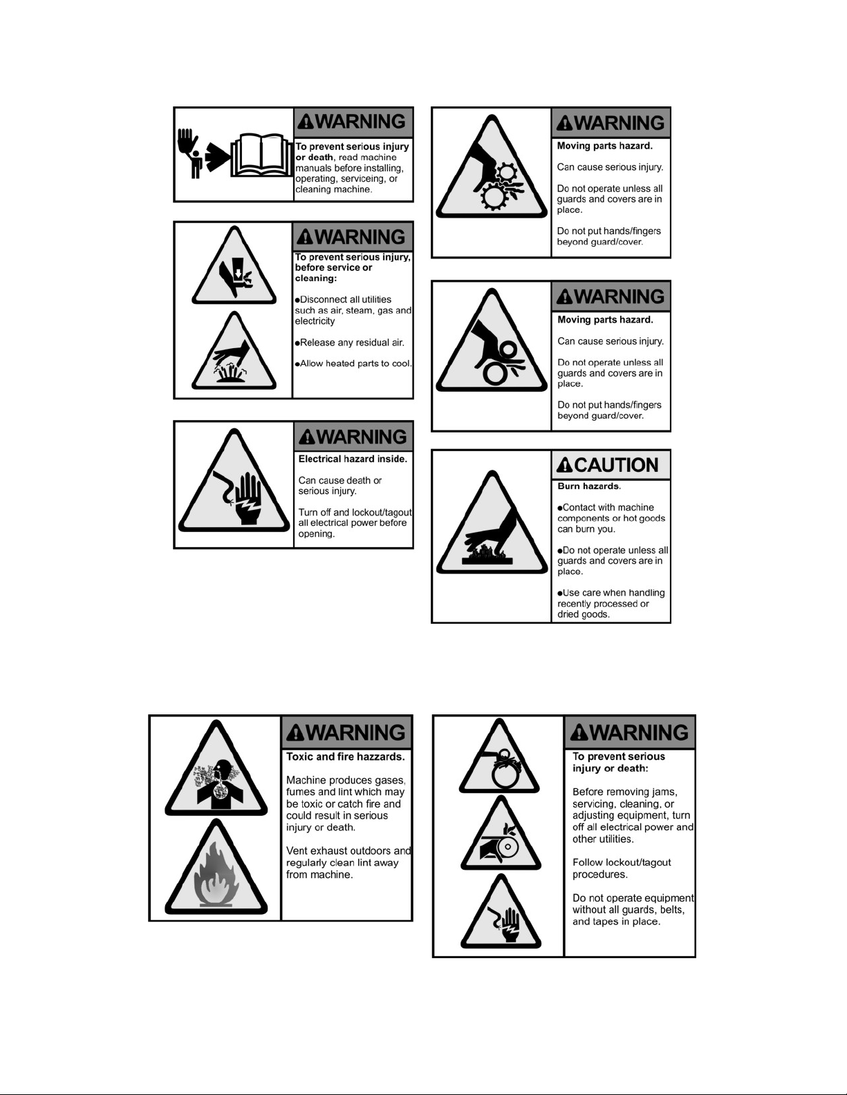
Figure 2.1: Key Symbols
Figure 2.2: Key Symbols
4

Natural Gas or Liquid Propane Gas (LP Gas) heated equipment installation must comply with
state and local codes, and in the USA, in accordance with the National Fuel Gas Code. Elsewhere,
the equipment should comply with ANSI Z22.1 or CSA B149.
Provisions must be made for adequate make-up air and ventilation, and access for equipment
service and installation.
2.5 Installation and Operational Safety Instructions
1. Read all instructions prior to operating this equipment.
2. Ensure that the equipment is properly grounded before applying power and operation be-
gins.
3. Do not process goods that have been previously cleaned in, soaked in, or exposed to gasoline,
dry cleaning chemicals, or any other flammable or explosive materials, as they could catch
fire or explode without warning, even after being washed.
4. Do not allow children to play in or around or operate this equipment.
5. Check the operation of all safety interlocks at the start of every shift. If the interlocks do not
stop the equipment immediately, the machine must be removed from service. Notify your
immediate supervisor, and do not operate the machine.
6. Never attempt to service the machine while it is running. Never reach over, under, around, or
behind any safety device, or into any area near moving parts or hot surfaces without shutting
off power and allowing the machine to adequately cool.
7. Read, understand, and follow all safety instructions. Do not come close to moving parts and
hot surfaces. Do not wear loose clothing, jewelry, neckties, or any other garment that could
become caught in the machine while operating or near the machine.
8. Only a qualified technician should attempt to service or repair the ironer.
9. Do not install the machine in an area where it could be exposed to water or weather.
10. Do not alter or tamper with the control system.
11. To reduce the risk of fire, do not process plastics or articles containing foam rubber or simi-
larly textured rubber-like materials.
12. Keep the area near the exhaust ducting clean and free of lint, dust, dirt or debris.
13. Keep the interior and exterior of the machine clean of lint, dirt, dust and debris. The inte-
rior of the machine, along with the exhaust ductwork should be periodically inspected and
cleaned to avoid potential fires (lint is highly flammable).
14. Improper installation, operation and maintenance of this machine can cause exposure to sub-
stances in the fuel or from combustion that can cause serious illness or death. The machine
must be exhausted to the outside.
5

15. Always disconnect the electrical service from the machine and allow it to cool before per-
forming service.
16. This machine must be installed according to the installation instructions. All exhaust, elec-
trical connections, and gas or steam connections must comply with state and local codes and
must be made by a licensed installer where required.
6

Chapter 3
Installation
3.1 Installation Note
Caution: this machine may only be installed, adjusted, updated, and started up by authorized
technicians or resellers.
The machine must be installed in accordance with current standards and regulations, in a room
with sufficient make-up air and exhaust.
3.2 Receiving Inspection
Upon receipt of the equipment visually inspect for shipping damage and note any damage with
the carrier before signing the shipping receipt, or advise the carrier of the damage as soon as it is
noted.
If damage is discovered, a written claim must be filed with the carrier as soon as possible.
Note: Warranty is void if the equipment is not installed according to instructions. The installation
must comply with the minimum requirements listed in this manual. All national, state, and local
codes must be followed including but not limited to gas, electrical, plumbing, and HVAC. Due to
various requirements, statutory codes should be well understood before installation.
Important: The ironer should be transported and handled in an upright position.
7

3.3 Electrical Installation
Refer to Table 3.2 on page 16 for full details on the electrical requirement for your specific model
prior to installation.
Electrical connections should be made by a qualified electrician in accordance with all applicable
codes or requirements. Use a separate branch circuit to power each machine. Do not share circuits
with lighting or any other equipment.
Because this is a vibrating machine, use SO cable (or similar) with a twist-lock plug to connect
the machine to main power. A shielded liquid tight or approved flexible conduit with proper
conductor of correct size installed in accordance with National Electric Code (USA) or other appli-
cable codes is required. The connection must be made by a qualified electrician using the wiring
diagram provided with the machine.
For personal safety and for proper operation the machine must be grounded in accordance with
state and local codes and in the USA in accordance with the National Electric Code, article 250-96.
The ground connection must be to a proven earth ground, not to conduit or water pipes.
Do not connect the ground to the neutral (N) leg at the terminal strip (if so equipped).
If a DELTA supply system is used, the high leg should be connected to L3, since control voltage is
derived from L1 and L2.
Note:
Ensure that all power connections are tight. Loose connections will
cause burned wires and contactors on electrically heated machines.
Check the electrical connections at the incoming power terminal block,
contactors, and heating elements at installation, after the first week of
operation, and quarterly thereafter. Failure of switchgear due to negli-
gence in this area is not covered under any warranty!
3.4 Gas Connection
3.4.1 Gas Supply Line
•1” IPS pipe is recommended.
•1” approved tubing is acceptable for lengths under 25 ft (6.1 m) if local codes and gas supplier
permit.
•Must include 1/8” NPT minimum plugged tapping accessible for test gauge connection,
immediately upstream of the gas connection to the ironer (see figure 3.1 on page 9).
8

Figure 3.1: Gas Plumbing Detail
•Must include a shutoff valve:
An individual manual shutoff valve must be installed within 6 feet (1.8m) of the equip-
ment in accordance with the National Fuel Gas Code, ANSI Z223.1. The location should
be easy to reach for opening and closing.
3.4.2 Gas Supply Connection Requirements
There are many methods by which the IC series ironer can be connected to the gas supply. Follow-
ing are some guidelines for methods of connection.
Option 1:
Flexible stainless steel gas connector:
If local codes permit use a new flexible stainless steel connector (design certified by the American
Gas Association or CSA International) to connect between the ironer and the gas supply line. Use
an elbow and a 1”’ flare x 1”’ NPT adapter fitting between the stainless steel gas connector and the
gas inlet of the machine as needed to prevent kinking.
Option 2:
Other approved piping:
Lengths under 25 feet (6.1m) use 1”’ approved tubing.
Lengths over 25 feet (6.1m) should use larger piping.
Pipe joint compounds that resist the action of gas must be used. DO NOT USE TEFLON R
/PTFE
TAPE.
9

IMPORTANT: Be certain the ironer is configured for the type of gas being used. The gas type is
shown on the serial sticker on the electrical panel of the unit.
Inlet Pressure
Use a manometer to verify that the inlet pressure meets the following requirements:
Natural Gas service must be supplied at 8-14 inches of water column pressure.
LP Gas service must be supplied at 11-14 inches of water column pressure.
If the incoming gas pressure exceeds the above, install a locally obtained gas regulator that has
sufficient BTU capacity to supply the machine (Maxitrol 325-5AL for up to 300,000 BTU, 327-7L
for up to 900,000 BTU or equivalent). A chattering gas valve indicates improper line pressure, not
a faulty gas valve.
Manifold Pressure (Secondary)
Be sure to check the manifold pressure. Use a manometer to verify that the manifold pressure
matches the information on the serial sticker and the type of gas being used. A separate gas
regulator (locally obtained) must be installed if the incoming line pressure is greater than 14 inches
water column pressure.
1. Connect the manometer to the pressure connection on the gas valve (disconnect gas service).
2. Restore gas service and determine the pressure while the burner is ignited. The pressure
must match the indicated manifold pressure on the serial sticker.
Gas Conversion Notice: Do not connect a machine configured for Natural Gas to LP Gas service or
vice-versa without a qualified service technician doing a proper conversion. After the reconfigura-
tion is complete, the manifold pressure must be verified. See Section A on page 47 for conversion
details.
3.5 Steam Connections
For best results, operate with a steam pressure of 90-125 psi (6.2-8.6 bar). The steam inlet and
return are located on the rear of the machine. The inlet is marked as such and is 3/4” NPT. The
return is marked as such and is 1/2” NPT.
Important: Insulate all steam and return lines for the safety of the operator and service technician.
Important: All steam components must be rated for a minimum of 200 psi (14 bar) working pres-
sure. Shut off valves must be installed upstream of the steam inlet, and downstream of the steam
trap so that the equipment can be isolated for maintenance or emergency.
Important: Support all steam lines and components to minimize the load on the steam connections
to the ironer.
Obtain steam service piping from a steam system supplier or a qualified steam fitter.
10

Figure 3.2: IC Series - Proper Exhaust is critical for safety!
Use a minimum of 12 inch (300mm) rise above the header to prevent condensate from draining
into the ironer. Do not make a steam connection to the header with a horizontal/downward facing
tee or elbow.
Wherever possible, horizontal runs of steam lines must gravity drain to the steam header. Water
pockets or improperly drained headers will yield poor results due to wet steam.
Install a union and valve in the steam supply and return lines for ease of service.
Install an inverted bucket trap with strainer and a check valve. For best results, install the trap at
least 18 inches (450mm) below the inlet and as close to the machine as possible. Install the trap
according to the instructions with the unit, noting the steam flow direction. If the steam is gravity
returned to the boiler, install a vacuum breaker and check valve in the return line near the machine.
Note that all return plumbing must be below the return inlet.
To prevent eventual water hammer, route all return lines below steam outlets.
3.6 Exhaust Requirements
For best results, install the machine near an outside wall in order to keep the exhaust duct length
as short as possible, and to provide a source of make-up air. The rear of the ironer should not
be blocked. Blocking the air inlets prevents proper combustion, and will yield poor results, and
possibly harmful combustion byproducts. See recommended exhaust style in Figure 3.3 on page
12.
Important: Do not interrupt the flow of make-up air or the exhaust!
For maximum efficiency and minimum lint accumulation the ironer must be exhausted to the
outdoors by the shortest possible route. Properly sized exhaust ducts are essential for proper
11

Figure 3.3: IC Series - Exhaust Detail
operation. Any 90-degree elbows used should be sweep type, however, 45-degree elbows are
preferable as they don’t create as much back pressure. Exhaust ducts must be assembled such that
all interior surfaces are smooth so the joints do not permit the accumulation of lint. Do not use
plastic or thin foil ducts — rigid metal ducts are recommended. Use exhaust ducts made of sheet
metal or other noncombustible material. Do not use sheet metal screws or fasteners on exhaust
pipe joints which extend into the duct and catch lint. Use duct tape or pop-rivets on all seams and
joints. The maximum allowable back pressure is 0.3 inches water column. Don’t guess, measure!
Note: Check for proper exhaust fan rotation direction before placing the equipment into ser-
vice. If the rotation is incorrect, remove power from the machine and exchange any two incom-
ing power leads. (3 phase machines only)
Note: Avoid locating the exhaust next to the fresh air supply intake.
Note: Avoid the use of ”booster fans”.
3.7 Fresh Air Requirements
When the ironer is operating, it draws in room air to carry heat and moisture from the ironed
goods and exhausts it out of the building. Therefore, the room air must be continually replenished
from outside the building.
If the make-up air is inadequate, efficiency will be adversely affected. Ignition problems and air
flow alarms may result.
12

Air supply (make-up air) must be given careful consideration to assure proper performance of each
ironer. An unrestricted source of air is necessary for each ironer. As a general rule, an unrestricted
air entrance from the outdoors (atmosphere) of a minimum of 1 sq ft is required for each ironer. If
registers or louvers are installed over the openings, then the area must be increased by at least one
third.
Allowances must be made for remote or constricting passageways or where ironers are located at
excessive altitudes or predominantly low-pressure areas.
Note: Avoid locating the exhaust next to the fresh air supply intake.
The flow of fresh air required make-up air is as follows:
3.8 Handling and Unpacking
Upon delivery, the ironer must be in perfect condition and the packing material must not be incom-
plete or damaged. Pay attention to the markings on the packaging (e.g. FRAGILE, UP/DOWN,
PROTECT FROM RAIN, etc).
Provide for adequate lifting and handling devices in order to proceed safely.
The ironer must be handled using a lift-truck of sufficient capacity and the truck forks must be
opened as much as possible to avoid toppling the ironer.
The ironer must be lifted at its center (center of gravity on the axis).
Do not drop or turn the ironer over, e.g. when unloading.
Note: lifting with slings or straps is not recommended, as there is a imminent risk of damaging
the ironer.
3.8.1 Shipping Brackets
Ensure that both shipping brackets are removed when machine is placed in its final location. The
top panel must be removed in order to access the brackets. Be sure to retain the screws and brackets
in case of future relocation of the ironer. Refer to figure 3.4 on page 14.
3.9 Room Requirements
The ironer must be installed in a well-ventilated room (particularly when using gas heating) with
correct lighting and an ambient temperature not exceeding +10◦C to +40◦C / 50◦F to 105◦F
(temperature limits for the AC drive for the main motor). Below +10◦C/50◦F, the temperature
sensor will not work and the control panel will display an alarm (AL7).
13

Figure 3.4: Remove shipping brackets prior to operation
Sufficient space must be provided around the ironer to allow for correct operation:
1. 5-10cm (10-12in) minimum at the back to allow for ventilation.
2. 60-80cm (24-32in) on each side to allow for servicing and maintenance.
3. Sufficient space must be provided at the front of the ironer to allow the operator to work
correctly and safely.
Leveling should be carried out on a hard and stable floor that can support the significant weight
of the ironer (400 to 500kg on 1.6 to 2 m2or 880-1100 lbs on 18-22 ft2).
The installation of this ironer requires a floor that can support a minimum of 500kg per m2or 50
lbs per ft2.
14

Table 3.1: IC-20 General Specifications
Model Metric US IC-2079 IC-20102 IC-20130
Number of Rolls # 1 1 1
Roll Diameter mm inch 500 20 500 20 500 20
Working Width mm inch 2000 79 2600 102 3300 130
Speed Range m/min ft/min 1.5-8 4.9-26 1.5-8 4.9-26 1.5-8 4.9-26
Sound Level dB 63 65 65
Dimensions
A - Width mm inch 2810 110.6 3410 134.3 4110 161.8
B - Depth mm inch 956 37.6 956 37.6 956 37.6
C - Height mm inch 1189 46.8 1189 46.8 1189 46.8
Exhaust System
Air Flow, Primary cmm cfm 20 700 20 700 20 700
Exhaust Duct mm inch 153 6.0 153 6.0 153 6.0
Electric Heat
Consumption kW 31.5 40.5 54
Roll Motor kW HP 3/8 1/2 3/8 1/2 3/8 1/2
Fan Motor kW HP 1/4 1/3 x 2 1/4 x 2 1/3 x 2 1/4 x 2 1/3 x 2
208-240VAC, 50/60Hz, 3PH Amps Breaker 100 125 125 150 160 200
380-480VAC, 50/60Hz, 3PH Amps Breaker 50 60 63 75 100 125
Gas
Heat Input BTU 136,500 187,600 235,500
Inlet NPT 1 1 1
Roll Motor kW HP 3/8 1/2 3/8 1/2 3/8 1/2
Fan Motor kW HP 1/4 x 2 1/3 x 2 1/4 x 2 1/3 x 2 1/4 x 2 1/3 x 2
120VAC, 50/60Hz, 1PH Amps Breaker 8 15 8 15 8 15
208-240VAC, 50/60Hz, 1PH Amps Breaker 4 15 4 15 4 15
208-240VAC, 50/60Hz, 3PH Amps Breaker 2 15 2 15 2 15
380-480VAC, 50/60Hz, 3PH Amps Breaker 2 15 2 15 2 15
Steam
Steam consumption BHP 5 7 8
Steam inlet NPT 3/4 3/4 3/4
Condesate return NPT 1/2 1/2 1/2
Steam pressure (max) bar psi 10 145 10 145 10 145
Roll Motor kW HP 3/8 1/2 3/8 1/2 3/8 1/2
Fan Motor kW HP 1/4 1/3 x 2 1/4 x 2 1/3 x 2 1/4 x 2 1/3 x 2
120VAC, 50/60Hz, 1PH Amps Breaker 8 15 8 15 8 15
120VAC, 50/60Hz, 1PH Amps Breaker 8 15 8 15 8 15
208-240VAC, 50/60Hz, 1PH Amps Breaker 4 15 4 15 4 15
208-240VAC, 50/60Hz, 3PH Amps Breaker 2 15 2 15 2 15
380-480VAC, 50/60Hz, 3PH Amps Breaker 2 15 2 15 2 15
Weight & Shipping
Net Weight kg lbs 925 2035 1200 2640 1436 3159
Shipping Weight kg lbs 974 2143 1270 2794 1475 3245
15

Table 3.2: Electrical Requirements
Electrical Requirement - Electrical Heating
Model IC-2079 IC-20102 IC-20130
Motor Power (kW / HP) 0.875 / 1.17 0.875 / 1.17 0.875 / 1.17
Heating Power (kW) 31.5 40.5 54
Max kVA 40.5 51.7 68.6
Breaker Size 380-460V 60 70 125
208-230V 100 150 200
Cable Size (mm2/ AWG) 380-460V 10 / 7 16 / 5 25 / 2
208-230V 25 / 3 35 / 2 35 / 2
Electrical Requirements - Gas Heating
Model IC-2079 IC-20102 IC-20130
Motor Power (kW / HP) 0.875 / 1.17 0.875 / 1.17 0.875 / 1.17
Max kVA 1 1 1
Breaker Size
380-460V 15 15 15
208-230V 10 15 15
120V 15 15 15
Cable Size (mm2/ AWG)
380-460V 2.5 / 14 2.5 / 14 2.5 / 14
208-230V 2.5 / 14 2.5 / 14 2.5 / 14
120V 2.5 / 14 2.5 / 14 2.5 / 14
Table 3.3: IC-20 Make-up Air Requirements
Model Metric US IC-2079 IC-10201 IC-20130
Air Flow cm/hr cf/hr 60 2200 90 3600 120 4400
16
This manual suits for next models
3
Table of contents
Other B&C Iron manuals


