B&G electronics PW-50 User manual

PW-50 V5
PLEASE READ BEFORE USING THE EQUIPMENT
EN 1.3
INSTALLATION AND OPERATION MANUAL
English

PW-50 V5 PW-50 V5
2 3
COMPONENTS AND RECOMMENDED LOCATIONS IN THE VEHICLE
(1) Electronic unit
(1) Control keyboard & internal microphone
(1) 50W loudspeaker
(2) External microphones
(1) Internal speaker
(1) Keyboard harness
(1) Power cable (battery)
(1) Fuse 10A
(1) Speaker extension cable
(1) Loudspeaker and auxiliary load harness
INSTALLATION AND ELECTRIC DIAGRAM
To install the equipment, see the installation diagram on page 4.
Avoid leaving visible cables in the cabin to maintain the vehicle’s aesthetics unaffected.
If there are any cables left disconnected, insulate them with tape; disconnected cables
making an undesired contact can cause a malfunction.
Electronic Unit
Place it on a hidden location for aesthetic purposes. Make sure that the
location allows some ventilation to avoid overheating.
Digital Keyboard
To facilitate handling of the equipment, place the keyboard on a location
within the driver’s reach, such as the console of the vehicle. Clean the
surface where the keyboard is to be sticked to ensure an adequate
adherence. Remove the protective liner from the adhesive pad in the back
side and stick it to the surface.
To clean the keyboard, gently wipe it with a dry cloth. Do not use water or
any solvent.
Loudspeaker
When selecting the location for the loudspeaker, keep in mind that this
component is suitable for outdoor use but it is not immersion-proof.
The loudspeaker must be placed as far as possible from the keyboard
(where the internal microphone is located) in order to avoid feedback.
External Microphones
The microphones require an assembly procedure, shown on the next page.
There are two recommended locations to place them, see the installation
instructions on the next page.
Internal Speaker
Locate the speaker out of view, without affecting the sound.
EXTERNAL MICROPHONES INSTALLATION INSTRUCTIONS
Each microphone includes a shell to hold it
in place and protect it from the elements.
Depending on the installation procedure,
it can be more convenient to assemble
microphone and shell either before or after
the wiring.
For instance, if the wiring requires to pull
the cable through a narrow space, it is
recommended to assemble after wiring.
Microphone + shell assembly procedure
1. Insert the cable in the shell by pressing it with your nger. 2.Push the microphone into the shell (do not pull the cable!).
3.Remove the liner from the tape and stick it to the shell. 4.Stick the shell on the selected surface, previously cleaned
with a 1:1 solution of isopropyl alcohol in water.
Recommended spots to install the microphones
There are two recommended spots in the vehicle (see
gure to the left), they differ with regard to ease of
installation and audio reception volume.
You can select a location according to your preferences.
Location A
Inside the rearview mirror.
This location offers the highest
sound volume, yet the most
time consuming installation, as
it requires to take parts of the
vehicle apart.
Location B*
In the gap of the front doors.
Select a surface to place the
microphone, so that it faces to
the exterior from inside the gap.
Once the surface is selected,
the installation is fairly easy.
* WARNING!
On location B, place the
microphone slightly
downward to prevent
damage from water
clogging.
Shell
Microphone
Mounting
tape
CONTROL KEYPAD
& INTERNAL MIC
PW-50
ELECTRONIC UNIT
EXTERNAL MIC
EXTERNAL MIC
50W
LOUDSPEAKER
INTERNAL SPEAKER

PW-50 V5 5
Red
White
EXTERNAL MIC (L - R)
CONTROL
KEYPAD
Black
BATTERY
+ 12 V
INTERNAL SPEAKER
AUXILIARY
LOAD
WARNING
Gently handle the wires during the installation; pressing or forced
bending of the wires can cause internal damage and subsequent
malfunction.
Avoid placing the wires near from noise sources such as
alternators, high tension wires, etc.
If there are any cables left disconnected, insulate them with tape;
disconnected cables making an undesired contact can cause
malfunction.
EXTERNAL
LOUDSPEAKER
Grey
Grey
WIRING DIAGRAM
PW-50
V5
OPERATING PROCEDURES
All of the equipment’s functions are managed through a six button keyboard (see gure
below). Operate the buttons with your ngertips; do not use objects to press them.
MIC
Volume DOWN
PTT
HORN
Manual WAIL INTER
SIRENVolume UP
AUX
ACTIVATING FUNCTIONS
Intercom* Siren - SIREN tone
ON: press & release
OFF: press & release
ON: press & release
OFF: press & release
INTER enables the hearing of exterior
sounds through the internal speaker.
If during 5 minutes the equipment does
not detect any activity, INTER function
turns off (Automatic Shut Down, ASD).
Activates the reproduction of the tone
selected for SIREN.
The procedure to change this tone is
explained on the next page.
Public Address “PA”* Auxiliary
ON: press & hold
OFF: release
ON: press & release
OFF: press & release
PTT allows the driver to communicate
to the exterior through the keypad
microphone.
For a more private communication (lower
exterior volume), press PTT while in INTER
mode. For a more public communication
(louder exterior volume), press PTT while
in SIREN, AUX SIREN or stand-by (with no
other active function) mode.
Both volumes are set following the same
keypad procedure.
AUX function either turns on an auxiliary
siren tone “AUX SIREN” or activates an
auxiliary load “AUX LOAD”, depending on
the subfunction assigned to it.
Siren - WAIL tone Siren - HORN tone
ON: press & hold
OFF: release
ON: press & hold
OFF: release
Activates the reproduction of the WAIL
siren tone.
Activates the reproduction of the HORN
tone.
If acoustic feedback occurs while INTER or PTT are on, AFC (Automatic Feedback Control) will trigger to prevent
feedback. AFC is further explained ahead in this manual.
*
PW-50 V5 PW-50 V5
6 7
SETTING UP FUNCTIONS
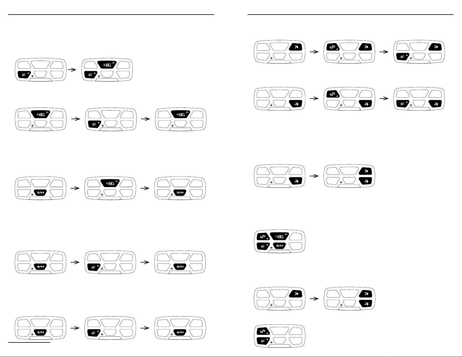
Setting up HORN tone
The default tone is American HORN, although the equipment allows to choose between
American HORN and B&G HORN, as explained below.
1. Press and hold HORN.2.While HORN is held, press and hold
SIREN (3 s) until the tone changes.
3.To change tone again, repeat steps
1 & 2.
Setting up SIREN
SIREN function allows to choose among 4 different tones: WAIL, Hi-Lo, PHASER & YELP.
1. Press and hold SIREN (5 s) until the
siren sound briefly pauses.
2.Press HORN to choose among tones. 3.Press SIREN to nish setup.
Setting up AUX
AUX allows to either play an auxiliary siren tone, or change the activation state of an
auxiliary load up to 15 Amp (useful to manage a light set or other devices).
1. Press and hold AUX (5 s).
If it beeps once, it’s set to AUX LOAD.
If siren stops & restarts, it’s set to
AUX SIREN.
2.Press SIREN to switch among AUX
LOAD and AUX SIREN.
If it beeps once, it’s set to AUX LOAD.
If siren stops & restarts, it’s set to
AUX SIREN.
3.Press AUX to nish setup.
Upon nishing beeps twice.
Setting up AUX SIREN tone
With AUX set to AUX SIREN, it is possible to select the AUX SIREN tone to one of the
available tones (WAIL, Hi-Lo, PHASER or YELP).
It is not possible to set the same tone for both SIREN and AUX SIREN, meaning that while
setting AUX SIREN, the SIREN tone in use will be unavailable; also, if the AUX SIREN tone
is selected for SIREN, AUX SIREN’s tone will automatically change.
1. Press and hold AUX (5 s) until the siren
sound briefly pauses.
2.Press HORN to switch among the
available tones.
3.Press AUX to nish setup.
Setting up AUX LOAD
With AUX set to AUX LOAD, it is possible to set AUX LOAD in a way that it gets activated
together with SIREN (for instance, that when SIREN sounds, a light set associated to AUX
LOAD turns on)*, in addition to the activation by pressing AUX.
1. Press and hold AUX (5 s) until you hear
1 beep.
2.Press HORN to switch AUX LOAD mode.
If it beeps once, it’s set to independent.
It it beeps twice, it turns on with SIREN.
3.Press AUX to nish setup.
Setting the volume of the internal speaker, “internal volume”
1. While INTER is on, press and hold
INTER.
2.While INTER is held, press WAIL to
increase volume.
3.While INTER is held, press HORN to
decrease volume.
Setting the volume of the external loudspeaker, “external volume”
1. Press and hold PTT.2.While PTT is held, press WAIL to
increase volume.
3.While PTT is held, press HORN to
decrease volume.
External Volume Auto-Adjustment (VAA)
In addition to the manual adjustment, the equipment is capable of detecting the vehicle’s
level of acoustic isolation and adjust the maximum external volume accordingly.
To perform this procedure, close all of the vehicle’s doors and windows, and follow the
steps explained below.
To cancel the procedure, press PTT.
1. Press and hold PPT.
Remain silent during the procedure.
2.While PTT is held, press INTER.
Release both upon hearing a beep.
3.Wait up to 30 s, the equipment will beep
2 times when VAA has nalized.
Enabling Hidden Siren Function
The equipment allows to silence the siren sounds, meaning that when this function has
been enabled and activated, the pressing of any of the siren buttons (SIREN, WAIL, HORN,
AUX SIREN) will not yield a response.
1. To switch between both states, press simultaneously WAIL,
HORN, AUX, SIREN, and hold for 5 s.
2.If it beeps 1 time, Hidden Siren is enabled.
If it beeps 2 times, Hidden Siren is disabled.
Activating / Deactivating Hidden Siren
Once Hidden Siren has been enabled, it is possible to activate it to effectively silent all
sirens, and deactivate to return all sirens to normal function.
1. To activate Hidden Siren, press and
hold INTER.
2.While INTER is held, press and hold
PTT until keyboard’s backlights blink.
3.Sirens will now be silenced.
1. To deactivate Hidden Siren, simultaneously press and hold
WAIL and HORN until keyboard’s backlights blink.
2.Sirens will now sound.
By default, AUX LOAD is set to activate independently from SIREN.*

PW-50 V5 8
AUTOMATIC FEEDBACK CONTROL (AFC)
If acoustic feedback would occur while PTT or INTER are on (caused, for instance, by the
opening of a door or window), the equipment will detect and automatically x the issue
by decreasing the volume. After the event takes place, the equipment will attempt to rise
the volume back to the level dened by the user, as long as AFC is not triggered again.
ENERGY SAVING FEATURES (Automatic Shut Down, ASD)
Partial Shut Down (PSD)
The equipment constantly tracks the incoming voltage status. If the incoming voltage
drops below 12.6VDC, after 20 seconds of inactivity the equipment activates PSD mode.
This change is indicated by the turning off the keyboard’s backlights. While on PSD mode,
upon pressing any key the respective function will execute normally and the equipment
will return to normal energy consumption mode.
Total Shut Down (TSD)
If the incoming voltage drops below 11.5VDC, after 60 seconds the equipment will
automatically shut down any function and auxiliary load. While on TSD, upon pressing
any key the backlights will blink 3 times and the function controlled by the pressed key
will not execute.
Once the equipment detects that the incoming voltage exceeds 12.5VDC again, the
equipment will return to its normal operation.
TECHNICAL SPECIFICATIONS
DIMENSIONS
Electronic Unit 3.7 H x 10.9 W x 14.8 D cm 1.5’’H x 4.3’’W x 5.8’’D
Loudspeaker 13.2 H x 9.4 W x 11.3 D cm 5.2’’H x 3.7’’W x 4.5’’D
Keyboard Control 2.5 H x 0.7 W x 5.4 D cm 1.0’’H x 0.3’’W x 2.1’’D
Internal Speaker 8.0 H x 5.6 W x 9.5 D cm 3.2’’H x 2.2’’W x 3.7’’D
INPUT VOLTAGE 12 - 14.9 VDC
INPUT CURRENT 4 Amps @ 13.6 VDC
STAND BY CURRENT <200 mA
AUDIO FREQUENCY 330Hz - 5600 kHz
OUTPUT POWER 42W RMS - 8 Ohm
SIREN FREQUENCY 440 - 1750 Hz
LOW VOLTAGE SHUTDOWN If voltage drops below 11.5V for 60 seconds or longer, the equipment will
cease to work and resume operation when system voltage exceeds 12.5V
B&G ELECTRONICS
ONE YEAR LIMITED WARRANTY
BYG Electrónica S.A.S. guarantees that this product leaves the factory free from defects related to materials and
manufacturing. If for any reason a failure related to materials and manufacturing were to occur during the period
of one year after the date of purchase, BYG Electrónica S.A.S. would repair or replace the failing equipment free
of charge.
This warranty shall be voided if the product is modied, tampered with, misused, or subjected to abnormal working
conditions. This warranty does not cover physical damage to the product surface. This warranty does not apply
when the malfunction results from the use of this product in conjunction with accessories, other products, or
peripheral equipment not designed by BYG Electrónica S.A.S.
Other manuals for PW-50
2
Table of contents
Other B&G electronics Recording Equipment manuals


