B&K 281 User manual

LIK,
Model
281
O
i
INSTRUCTION
:
MANUAL
DIGITAL
MULTIMETER
Product
of
DYNASCAN
CORPORATION
1801
West
Belle
Plaine
Avenue,
Chicago,
Illinois
60613

Dear
Friend:
Congratulations
on
your
purchase
of
B
&
K—Precision
Test
Equipment,
and
welcorne
to
the
B
&
K
family.
We
hope
your
experience
with
your
new
test
equipment
will
make
you
a
lifetime
B
&
K
customer.
Your
instrument
is
backed
by
more
than
20
years
of
experience
in
designing
and
manufacturing.
Our
most
important
goal
is
your
satisfaction.
At
B
&
K,
test
equipment
is
made
to
meet
the
demands
of
the
field
focusing
on
dependability
and
accuracy.
We
also
concentrate
on
simplicity
and
operating
ease
with
features
that
reduce
the
possibility
of
human
error
and
speed
the
servicing
process.
In
order
to
determine
the
type
of
test
units
that
are
needed
we
have
been
guided
by
letters
and
reports
from
technicians
and
engineers
who
use
the
equipment
daily.
Our
field
tests
and
studies
have
helped
provide
better
and
faster
service
techniques.
Close
contact
has
been
maintained
with
the
manu-
facturers
of
consumer
products
which
our
test
units
will
be
checking
and
trouble-shooting.
Key
personnel
in
our
company
cut
their
eye
teeth
in
the
TV
service
business.
This
is
why
we
have
more
"sensitivity"
for
the
problems
and
conditions
under
which
the
test
equipment
will
be
used.
B
&
K
product
designs
are
constantly
reviewed,
and
refinements
are
made
or
new
models
developed
to
meet
advances
in
our
industry
and
to
fill
your
needs.
We
set
our
standards
high
so
you
can
be
assured
that
the
B
&
K
test
instruments
you
buy
represent
advanced
design,
quality
construction,
and
dependable
long-term
performance
at
a
price
you
can
afford.
If
you
have
any
comments
or
thoughts
about
our
products,
or
test
equipment
in
general,
I
would
be
delighted
to
hear
from
you.
Thanks
for
your
confidence
in
B
&
K
and
we
look
forward
to
serving
you
for
a
long
time
to
come.
Sincerely,
re
а
Carl
Korn
President

INSTRUCTION
MANUAL
FOR
Model
281
DIGITAL
MULTIMETER
B
&
K
DIVISION
OF
DYNASCAN
CORPORATION
1801
West
Belle
Plaine
Avenue
Chicago,
Illinois
60613

TABLE
OF
CONTENTS
Page
INTRODUCCION
„М
Аа.
ce
ce
2226”...
3
SDECIOCATMIONSE
т
уо
ышы
I
LT
зз»
I
RETE
3
CONTROLS
AND
FEATURES,
coce
tete
6
OPERATION
а
Le
8
Turning
Instrument
OWIE
EE
EP
EE
cde
„т
Мы
ол...
9
DCG:
Voltage
В
епі
АА
9
AG
Voltage
Measurements)
3...
9
IDG«CurrentiMcasurements
.
oeer
50.
Fm...
rer
rs
DEEST
10
AG
Gurrent
Measuremenis
Е...
vote
11
Resistance
Measurements
.......
оаа
о
о
I
MODEL
281
DIGITAL
MULTIMETER
THEORY
OF
GIDERUASIIQN.
КЕНЕ
a
ЖОККО
ЖИТТИ
no
СОО
S
NIE
12
MODEL
281
CALTBRATION
PROCEDURE”...
14
WARRANIEY
SERVICE
INSTRUCTIONS
.
..
35...
а...
.
RS
17

INTRODUCTION
Тһе
B
&
K—Precision
Model
281
Digital
Multimeter
is
a
significant
con-
tribution
to
the
instrumentation
market.
Low
cost
and
high
performance
have
been
engineered
into
this
instrument
to
make
available
to
the
service
technician,
industry
and
training
institutions
a
digital
multimeter
which
is
competitively
priced
with
existing
analog
meters
and
which,
at
the
same
time,
exceeds
the
performance
of
these
meters.
In
addition,
the
basic
instru-
ment
has
been
designed
for
maximum
simplicity
of
operation
and
minimum
error
of
reading.
The
basic
design
features
of
this
instrument
make
it
an
ideal
replacement
for
existing
VTVM's,
multimeters
and
FET/VOM’S.
The
instrument
is
"capable
of
measurement
of
DC
and
AC
current
and
Ohms.
The
high
input
impedance—10
megohms
on
all
yoltage
ranges—as
well
as
the
wide
resistance
range—10
ohms
full
scale
to
10
megohms
full
scale—make
this
instrument
an
ideal
replacement
for
conventional
analog
type
instruments.
In
addition
to
providing
equivalent
functions
and
ranges,
the
inherent
accuracy
of
this
instrument
provides
a
significant
margin
of
performance.
SPECIFICATIONS
DC
VOLTAGE
Ranres
Жеты...
--0—100mv,
1.00Volt,
10.0Volts,
100Volts,
1.00Kilovolt.
Oycuianpe
...
т...
100
percent
to
--
199гау,
1.99Volts,
19.9Volts,
199Volts,
1.5Kilovolts.*
Maximum
DC
Input
...1500
Volts
d-c
or
d-c
plus
a-c
peak.
EECGUITACY
ste
REC
+l
percent
of
full
range,
+1
digit.
Input
Impedance
......
10
megohms
Polarity
Switching
.....
Function
switch
provides
polarity
reversal
capa-
bility.
Wrong
Polarity
Indication
+
s
e.
If
a
DC
voltage
of
the
wrong
polarity
is
applied
to
the
input,
the
first
digit
(“1”)
will
remain
on
and
the
second
and
third
digits
will
remain
off.
Overrange
Indication
..If
the
input
voltage
exceeds
200
per
cent
of
full
scale,
the
first
digit
(“1”)
will
remain
off
and
the
second
and
third
digits
will
flash
on
and
off
to-
gether.
AC
VOLTAGE
(peak-reading
circuitry
calibrated
to
read
RMS
value
of
pure
sine
wave)
Ranges.
ТЕК
дам
0—100mv,
1.00Volt,
10.0Volts,
100Volts,
1.00Kilovolt
RMS.*
*Do
not
exceed
input
level
of
1500V
dc
or
1500V
(dc+ac
peak).
3
Я

Overrange
Maximum
AC
Input
..
Асёйтасу
И.
MOORE
Frequency
Response
..
Input
Impedance
......
Overrange
Indication
DC
CURRENT
REES
o
o
t
Voltage
Drop
(Measured
at
instrument
terminals).
Overrange
2
Accuracy
onm
...
Wrong
Polarity
Indication.
P
ы
Overrange
Indication
AC
CURRENT
Rappes
ыш.
2.
eee
Voltage
Drop
(Measured
at
instrument
terminals).
Отеапре
й.
„е-е
Сау
ЕА
Frequency
Response
Overrange
Indication
zc
1.5
per
cent
accuracy:
20Hz
to
1000925
*
Drame
бс
gie
100
per
cent
to
199mv,
1.99Volt,
19.9Volts,
.
199Volts,
1.00Kilovolt
RMS*.
dat
.1000V
RMS
or
1500Volts
peak.
ka
2-
1.5
per
cent
of
full
range
(Calibrated
с
|н».
10
megohms.
.
If
the
input
voltage
exceeds
200
per
cent:
T
full
scale,
the
first
digit
(*1")
will
remain
off
and
the
second
and
third
digits
will
blink
on
and
off
to-
gether.
*Do
not
exceed
input
level
of
1000V
RMS
or
1500V
peak.
Ф
0—100,a,
1.00ma,
10.0ma,
100ma,
1.00А.
.100ту,
at
full
range.
100
per
cent
to
199,a,
1.99ma, 19.9ma,
199ma,
1.99A.
z-
1.5
per
cent
of
full
range.
If
a
DC
current
of
the
wrong
polarity
is
applied
to
the
input,
the
first
digit
(“1”)
will
remain
on
and
the
second
and
third
digits
will
remain
off.
.
If
the
input
current
exceeds
200
per
cent
of
full
scale,
the
first
digit
("1")
will
remain
off
and
the
second
and
third
digits
will
flash
on
and
off
together.
0—100,a,
1.00ma, 10.0ma,
100ma,
1.00A.
100mV
RMS
at
full
range.
100
per
cent
to
199,2,
1.99ma,
19.9ma,
199ma,
1.994.
2
1.5
per
cent
of
full
range.
...20Н?
to
1000Hz.
.
.If
the
input
current
exceeds
200
per
cent
of
full
scale,
the
first
digit
(“1”)
will
remain
off
and
the
second
and
third
digits
will
flash
on
and
off
together.

RESISTANCE
Ranges...
.
Ne
0—10.0ohms,
100ohms,
1.00Kohm,
10.0Kohms,
айы
100Kohms,
1.00Mohm,
10.0Mohms.
Overrange
............
100
per
cent
to
19.9ohms,
199ohms,
1.99Kohms,
2,767)
19.9Kohms,
199Kohms,
1.99Mohms,
19.9Mohms.
Accuracy
un
à
2-2
per
cent
of
range,
10.0ohms,
to
1.00Mohm
I"
+3
per
cent
of
range,
10.0M
ohms
range
Test
Voltage
32:17...
0—10.0
ohm
range,
0.1
Volt
at
full
range;
100
ж
ohms
to
10.0Mohms,
1.0Volt
at
full
range.
Maximum
Test
Ситеп
Ж.С...
10ohms
10ma
oe
-
1000hms
10ma
22.
1Kohm
à
Ima
қ
10Kohms
100ua
"
aa
100Kohms
10да
1Mohm
lua
10Mohms
100na
CIRCUIT
PROTECTION
DC
Volts,
AC
Volts
....Diode
protection
together
with
series
current
limiting
resistance.
Ohms
Ranges
.........
Fuse
and
diode
protection.
OPERATING
TEMPERATURE
RANGE
10°С
to
40°C
No
degradation
in
accuracy.
POWER
SOURCE
......
117V
AC,
50/60Hz
POWER
CONSUMPTION
..........
15
Watts.
ACCESSORIES
(Included)
........
One
test
probe
assembly,
PR-21.
Instruction
manual
with
schematic
and
parts
list.
Spare
Ohms
fuse
(1/10A.,
3AG).
DIMENSIONS
......................--.-
Зот
WICHT
СЕ
м
5
Ibs.
5
site

CONTROLS
AND
FEATURES
(SEE
FIGURE
1)
Figure
1.
Operator's
Controls
and
Facilities
FUNCTION
switch
Selects
the
type
of
measurement
to
be
performed.
Also
used
to
turn
the
instrument
on
and
off.
RANGE
switch
Selects
the
desired
range
for
the
measurement
selected
by
the
FUNC-
TION
switch.
1A
jack
This
jack
is
used
when
measuring
dc
and
ac
currents
on
the
1A
range.
COM
jack
This
is
the
common
connection
to
the
instrument
input.
6

5:
10.
(+)
jack
This
is
the
“hot”
input
jack.
In dc
measurements
the
test
lead
connected
to
this
‘jack
is
normally
applied
to
the
positive
potential
point
in
the
circuit
under
test
when
FUNCTION
switch
is
in
the
+DCV
position.
NUMERICAL
READOUT
DIGIT
NUMBER
3
An
indication
between
0
and
9
is
obtained,
depending
upon
the
value
of
the
reading
displayed.
This
digit
is
identified
as
the
"3rd"
digit.
NUMERICAL
READOUT
DIGIT
NUMBER
2
A
reading
of
0
to
9
is
obtained,
depending
upon
the
value
of
the
measurement
performed.
This
digit
is
identified
as
the
"2nd"
digit.
NUMERICAL
READOUT
DIGIT
NUMBER
1
Either
an
off
(no
display)
or
a
“1”
is
displayed,
depending
upon
the
value
of
the
measurement
performed.
This
digit
is
used
when
readings
corresponding
to
full
scale
and
over
range
are
performed,
and
is
identified
as
the
"Ist"
digit.
Adjustable
Handle
'This
handle
can
be
used
for
carrying
the
instrument
and
can
also
be
used
as
a
tilt
stand
to
raise
the
front
panel
to
a
convenient
viewing
angle
when
desired.
The
handle
can
be
locked
into
any
desired
position
by
rotating
it
until
it
snaps
into
the
position
desired.
PR-21
Test
Probe
This
probe
is
used
for
all
measurements
performed.
This
probe
is
provided
with
a
selectable
100
КО
resistor
which
is
used
when
perform-
ing
dc
measurements
in
high
impedance
or
high
frequency
circuits.
The
resistor
isolates
the
cable
and
input
capacity
of
the
meter
from
the
circuit
in
which
the
measurements
are
performed.
This
reduces
capaci-
tive
loading
which
may
result
in
erroneous
reading.
NOTE
When
the
probe
resistor
is
used,
a
reading
error
of
minus
(—)
one
per
cent
is
introduced
because
the
100K
resistor
value
is
placed
in
series
with
the
internal
10
megohm
divider.
If
this
error
is
considered
signifi-
cant,
the
correction
is
made
to
the
reading
obtained
by
increasing
the
value
of
the
observed
reading
by
one
per
cent.
7
er
m
eee

OPERATION
S
EFL
t
TABLE
I
j
е
MEASUREMENTS
AND
INTERPRETATION
OF
=
DIGITAL
DISPLAYS
ae
<
TEE
T
SE
SET
CONNECT
DIGITAL
DISPLAY
|
À
TO
MEASURE
FUNCTION
RANGE
RED
.
FULL
100%
A
SWITCH
SWITCH
»
LEAD
-.
SCALE
OVERRANGE
.
+DCV/
0-100MV
+DCV/
100MW
(4)
Jack
100
199
—
-DCV
0-1V
—DCV
ІМ
e
(F)
Jack
1.00
1:99
0-10
V
10V
(+)
Jack
10:0
19.9
|
0—100
V
100
У.
-(-)
Jack
-
100
19%
|
А.
0—1000
У.
=
IKV
(+)
Jack
1.00
150%.
AC
0—100
MV
ACV
100
MV
(+)
Jack
100
199
Vorrs
0-1У
1V
(+)
Jac
1.00
1.99
0—10
V
10
V
(+)
Jac
10.0
199
-
0—100
V
100
V
(+)
E
100
199
0—1000
V
1KV
(+)
Jack
\
1.00
1.00**
DC
“0-100
na
РСА
100
na
(+)
Jack
7100
199
CURRENT
0—1
ma
1
ma
(+)
Jack
1.00—
1.99
0—10
ma
10
ma
(+)
Jack
10.0
19.9
0—100
ma
100
ma
(+)
Jack
100
199
0—1
Amp
1A
1A
1.00
1.99
AC
0-100
ya
АСА
100
ua
(+)
Jack
100
199
CURRENT
0—1
ma
]
ma
(+)
Jack
1.00 1.99
0—10
ma
10ma
(+)
Jack
10.0 19.9
0—100
ma
100
ma
(+)
Jack
100
199
0—1
Amp
1A
1A
1.00
1.99
OHMS
0-109
Onms
100
(+)
Jack
10.0
19.9
0—100
о
1000
(+)
Jack
100
199
0--1000
о
1Ко
(+)
Jack
1.00
1.99
0—10
Ko
10KQ
(+)
Jack
10.0
19.9
0—100
Ka
100KQ
(+)
Jack
100
199
0—1
Mo
1Mo
(+)
Jack
1.00
1.99
0—10
Mo
10Mo
(+)
Jack
10.0
19.9
Р
*Do
not
exceed
input
levels
of
1500
VDC
or
dc+ac
peak.
**Do
not
exceed
input
levels
of
1000
VRMS
or
1500
V
peak.
|
Table
I
is
provided
as
an
aid
in
operation
of
the
Model
281
and,
in
addition,
1
provides
interpretation
of
the
displays
obtained.
Note
that
the
decimal
location
changes
with
the
changes
in
position
of
the
RANGE
switch.
The
significance
of
the
decimal
location
must
be
known
to
assure
proper
inter-
pretation
of
the
readings
obtained.
Аааа
_

ar
қ.
элг,
'
+
TURNING
INSTRUMENT
ОМ
à
бес
FUNCTION
switch
1
to
the
OFF
position.
coded
the
line
cord
to
a
117
volt,
50/60
Hz
source.
ec
the
test
probe
assembly
11
to
the
meter.
Insert
the
dual-pin
D.
the.
(+)
pin
is
inserted
in
the
(7)
jack
6
and
the
(—)
pin
is
inserted
in
the
COM
jack
5.1
it
is
desired
to
measure
current
"dn
Ше
1
ampere
rangesthe
(+)
pin
is
connected
to
the
1
A
jack
4.
d.
Turn
the
instrument
on
by
rotate
the
FUNCTION
switch
to
the
OHMS
posi
ion.
;
24.
е;
Without
a
ee,
cted
across
the
test
leads,
the
overrange
indication
should
occu
causing.
e
first
digit
to
be
blanked
and
the
second
and
third
|
digits
to
flash
on
and
off
together.
Shorting
the
rn
id
leads
should
produce
a
zero
readi
g
(first
digit
off
and
a
“0”
display
on
the
second
and
third
px
rich
100K
probe
resistor
out.
.
DC
VOLTAGE
"MEASUREMENTS
~.
a.
Set
FUNCTION
switch
I
to
the
4-DCV
position
if
the
voltage
to
be
measured
is
positive
with
respect
to
common
reference
point,
or
to
the
—DCV
position
if
the
voltage
to
be
measured
is
negative
with
respect
to
a
common
reference
point.
Make
sure
that
the 100
Kohm
resistor
in
the
test
probe
is
switched
out,
viles
requie
to
provide
isolation
when
measuring
d-c
voltages
in
a
high
frequency
circuit.
b.
Set
RANGE
switch
3
as
required
for
the
voltage
amplitude
to
be
measured.
If
the
magnitude
of
the
voltage
is
not
known,
set
the
RANGE
switch
to
the
highest
position
and
reduce
the
settings
as
required
to
obtain
a
satisfactory
reading.
c.
Connect
the
negative
clip
lead
of
the
test
probe
assembly
11
to
the
common
point
of
the
chassis
or
equipment
in
which
the
measure-
ments
are
to
be
performed.
d.
Touch
the
tip
of
the
probe
to
the
voltage
point
to
be
measured.
A
reading
will
be
obtained
if
the
polarity
of
the
voltage
corresponds
to
that
selected
by
the
FUNCTION
switch.
If
the
polarity
is
re-
versed,
the
polarity
sensing
circuit
will
be
energized,
causing
the
first
digit
to
stay
on
and
the
second
and
third
digits
to
remain
off.
Reset
the
FUNCTION
switch
to
the
polarity
position
required
to
obtain
a
reading.
e.
If
the
amplitude
of
the
DC
voltage
measured
is
greater
than
twice
that
of
the
range
selected,
the
overrange
indication
will
become
operative
and
the
first
digit
of
the
display
will
remain
off
and
the
second
and
third
digits
will
flash
on
and
off
together.
The
RANGE
switch
should
then
be
adjusted
to
a
higher
range
as
required
to
obtain
a
satisfactory
reading.
f.
Refer
to
Table
1
for
correct
interpretation
of
the
reading
displayed.
.
AC
VOLTAGE
MEASUREMENTS
a.
Place
the
FUNCTION
switch
in
the
ACV
position.
b.
Switch
out
the 100
Kohm
resistor
in
the
test
probe.
9
йыз

с.
Set
the
RANGE
switch
to
the
desired
voltage
range.
If
in
doubt
about
the
actual
voltage
amplitude
to
be
measured,
always
use
the
highest
voltage
range
for
the
first
measurement
and
adjust
the
RANGE
switch
as
required
to
obtain
a
satisfactory
readout.
If
a
voltage
greater
than
twice
that
indicated
on
the
RANGE
switch
is
being
measured
the
over
range
indication
will
become
operative,
and
the
first
digit
will
be
blanked
and
the
second
and
third
digits
will
flash
on
and
off
together.
When
this
occurs,
a
higher
voltage
range
must
be
selected.
|
d.
Refer
to
Table
1
for
correct
interpretation
of
the
reading
displayed.
4.
DC
CURRENT
MEASUREMENTS
a.
Place
the
FUNCTION
switch
to
the
DCA
position.
b.
Switch
out
the
100
Kohm
resistor
in
the
test
probe.
с.
Place
the
RANGE
switch
to
the
desired
current
range
position.
CAUTION
Use
care
in
selecting
the
current
range
to
be
measured.
Make
sure
that
meter
is
inserted
in
series
with
the
load
in
which
the
current
is
being
measured.
Do
not
connect
the
meter
in
parallel
with
the
voltage
source
connected
to
the
load.
A
severe
current
overload
can
damage
the
current
shunts
provided
in
the
instrument.
When
connecting
the
multimeter
to
read
current
in
a
circuit,
the
power
to
the
circuit
should
first
be
removed.
The
following
rules
will
insure
that
the
propey
current
polarity
is
obtained.
(1)
When
inserting
the
test
leads
of
the
multimeter
on
the
positive
side
of
the
power
source
which
connects
to
the
load,
connect
the
positive
lead
of
ule
test
probe
assembly
at
the
voltage
source
and
connect
the
negative
lead
to
the
load.
(2)
When
inserting
the
multimeter
between
the
negative
power
source
terminal
and
the
load,
connect
the
negative
(black)
test
Ё
ead
to
the
negative
voltage
terminal
and
connect
the
positive
(red)
lead
to
the
load.
After
the
connections
have been
made
to
the
circuit
being
measured,
the
power
can
be
re-applied
and
the
measurement
performed.
If
the
polarity
of
the
current
being
measured
is
incorrect,
the
polarity
sensing
circuit
will
be
energized,
causing
the
first
digit
to
stay
on
and
the
second
and
third
digits
to
remain
off.
When
this
occurs
the
test
lead
connections
in
the
external
circuit
must
be
reversed,
after
first
removing
power
to
the
circuit
under
test.
If
the
magnitude
of
the
current
being
measured
exceeds
twice
the
amount
indicated
on
the
RANGE
switch
position
selected,
the
over
range
circuitry
is
energized,
causing
the
first
digit
to
remain
off
and
the
second
and
third
digits
to
flash
on
and
off
together.
When
this
occurs
immediately
remove
power
from
the
circuit
under
test
and
select
a
higher
current
range
before
proceeding
further.
10

g-
.
assembly
must
be
connected
to
the
1A
jack
4.
h.
When
using
the
ТА
current
range,
the
(+)
tip
of
the
test
probe
Refer
to
Table
1
for
interpretation
of
the
digital
readout
obtained.
-
AC
CURRENT
MEASUREMENTS
a.
b.
С.
g
Set
the
FUNCTION
switch
to
the
ACA
position.
Switch
out
the
100
Kohm
resistor
іш.
the
test
probe.
Set
the
RANGE
switch
to
the
desired
position.
If
in
doubt
about
the
magnitude
of
the
current
to
be
measured,
use
the
highest
current
range
and
then
adjust
the
RANGE
"s
as
required
to
obtain
a
satisfactory
reading.
If
the
IA
position
of
the
RANGE
switch
is
selected,
the
(+)
pin
of
the
test
probe
assembly
must
be
connected
to
the
1A
jack.
When
connecting
the
multimeter
for
current
measurements
remove
the
power
from
the
circuit
being
tested
while
the
connections
are
being
made.
Do
not
make
or
break
series
connections
to
the
circuit
under
test
with
power
applied.
If
the
magnitude
of
the
current
being
measured
exceeds
twice
the
value
of
the
range
selected,
the
over
range
circuitry
is
energized,
causing
the
first
digit
to
remain
of
and
the
second
and
third
digits
to
flash
on
and
off
together.
When
this
occurs,
immediately
remove
power
from
the
circuit
under
test
and
select
a
higher
current
range
before
proceeding
further.
Refer
to
Table
1
for
interpretation
of
the
readings
obtained.
RESISTANCE
MEASUREMENTS
CAUTION
Do
not
attempt
to
measure
resistance
in
a
circuit
in
which
the
power
is
applied.
Remove
power
and
make
sure
that
all
capacitors
are
discharged
before
attempting
in-circuit
resistance
measurements.
Set
the
FUNCTION
switch
to
the
OHMS
position.
If
the
OHMS
circuit
doesn’t
work,
you
may
have
burned
out
the
ohms
circuit
fuse
(F101)
by
making
a
resistance
measurement
in
a
“hot”
circuit.
To
replace
it,
remove
thé
two
screws
retaining
the
cover
and
carefully
lift
it
off.
Replace
F101
(Figure
2)
with
the
spare
fuse
clipped
to
the
rear
panel
on
the
inside
of
the
unit.
.
Switch
out
the
100
Kohm
resistor
in
the
test
probe.
Set
the
RANGE
switch
to
the
desired
position.
Connect
the
test
leads
across
the
resistance
to
be
measured.
.
If
the
resistance
value
being
measured
exceeds
twice
the
value
of
the
range
selected,
the
overrange
circuitry
is
energized,
causing
the
first
digit
to
remain
off
and
the
second
and
third
digits
to
flash
on
and
off
together.
Refer
to
Table
I
for
proper
interpretation
of
the
readings
obtained.
11
atm,
——
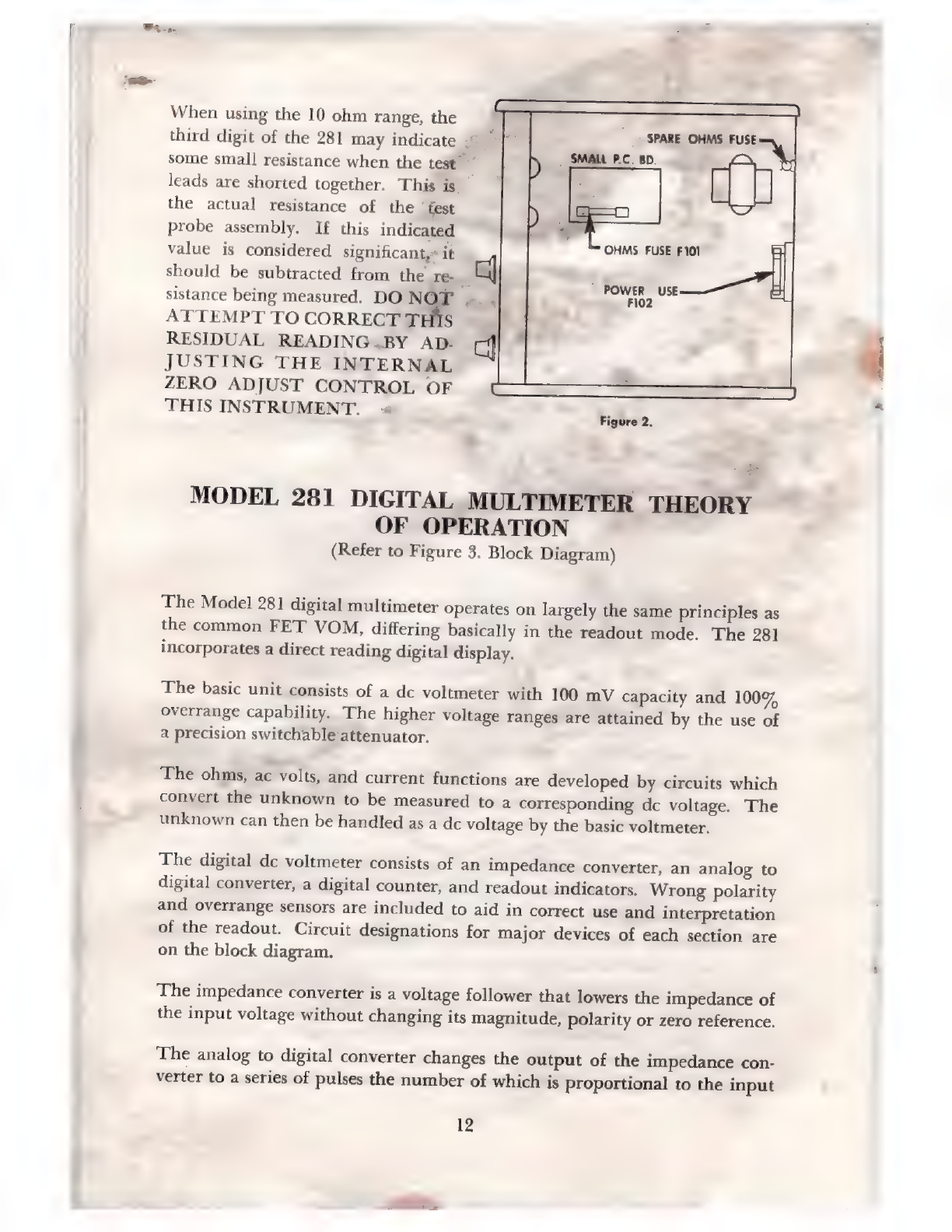
When
using
the
10
ohm
range,
the
third
digit
of
the
281
may
indicate
"
SPARE
opting
FUSE
some
small
resistance
when
the
test”
M
RE
n.
leads
are
shorted
together.
This
is
the
actual
resistance
of
the
test
probe
assembly.
If
this
indicated
value
is
considered
significant,
it
should
be
subtracted
from
the
re-
sistance
being
measured.
DO
МОЯ
=
ATTEMPT
TO
CORRECT
THIS
RESIDUAL
READING.BY
AD:
JUSTING
THE
INTERNAL
ZERO
ADJUST
CONTROL
OF
THIS
INSTRUMENT.
.
OHMS
FUSE
F101
=
POWER
USE
F102
Figure
2.
E.
MODEL
281
DIGITAL
MULTIMETER
THEORY
OF
OPERATION
(Refer
to
Figure
3.
Block
Diagram)
The
Model
281
digital
multimeter
operates
on
largely
the
same
principles
as
the
common
FET
VOM,
differing
basically
in
the
readout
mode.
The
281
incorporates
a
direct
reading
digital
display.
The
basic
unit
consists
of
a
dc
voltmeter
with
100
mV
capacity
and
100%
overrange
capability.
The
higher
voltage
ranges
are
attained
by
the
use
of
a
precision
switchable
attenuator.
The
ohms,
ac
volts,
and
current
functions
are
developed
by
circuits
which
convert
the
unknown
to
be
measured
to
a
corresponding
dc
voltage.
The
unknown
can
then
be
handled
as
a
dc
voltage
by
the
basic
voltmeter.
The
digital
dc
voltmeter
consists
of
an
impedance
converter,
an
analog
to
digital
converter,
a
digital
counter,
and
readout
indicators.
Wrong
polarity
and
overrange
sensors
are
included
to
aid
in
correct
use
and
interpretation
of
the
readout.
Circuit
designations
for
major
devices
of
each
section
are
on
the
block
diagram.
The
impedance
converter
is
a
voltage
follower
that
lowers
the
impedance
of
the
input
voltage
without
changing
its
magnitude,
polarity
or
zero
reference.
The
analog
to
digital
converter
changes
the
output
of
the
impedance
con-
verter
to
a
series
of
pulses
the
number
of
which
is
proportional
to
the
input
12

oe
*
voltage
in
millivolts;
i.e.
OmV
=
Ises,
1OmV
=
10
pulses,
100mV
=
100
pulses,
etc.
;
N
om
The
digital
counter
counts
the
output
pulses
from
the
analog
to
digital
con-
verter
and
stores
the
count
for
display
by
théfreadout
section.
The
readout
indicators
display
the
number
stor
including
the
overrange
digit;
thus
indicating
millivolts.
A
voltage
greater
than
199mV'
ар
at
the
input
of
the
im-
pedance
converter
would
result
in
a
count
greater
than
199.
However,
when
the
count
reaches
200
the
overrange
sensor
is
activa
ed,
blanking
the
over-
range
digit
and
flashing
the
readout
tubes,
uc
M
the
possibility
of
operator
confusion
due
to
an
erroneous
display.
=`
d
by
the
counter,
up
to
199
e
input
voltage
up
to
199
To
read
voltages
higher
than
199mV
a
switchable
precision
attenuator
is
placed
between
the
input
and
the
impedance
converter
such
that
the
input
voltage
is
divided
by
an
appropriate
multiple
of
ten
so
as
to
present
100mV
to
the
impedance
converter
at
the
selected
full
range
input
voltage.
To
read
ac
voltages
an
ac
to
dc
converter
is
placed
between
the
impedance
-—conyerter
and
the
analog
to
digital
converter
to
translate
the
ac
voltage
to
a
proportional
devoltage
readable
by
the
dc
voltmeter.
To
read
current
a
switchable
precision
shunt
is
connected
across
the
input
terminals.
The
shunt
is
selected
such
that
at
full
range
current
the
voltage
drop
across
the
input
is
100mV.
Thus
the
current
is
converted
to
a
directly
proportional
voltage
which
can
be
read
by
the
basic
digital
voltmeter.
eke
To
measure
resistance
a
constant
current
source
is
connected
to
the
input
so
that
the
voltage
dropped
is
proportional
to
the
resistance
to
be
measured,
thereby
changing
the
resistance
value
to
a
dc
voltage
usable
by
the
basic
voltmeter
circuitry.
ІСІ,01-5
IMPEDANCE
CONVERTER
#
FUNCTION
SWITCH
WRONG
POLARITY
SENSOR
IC8-17,
014-16
OHMS
BNALOG
TO
DIGITAL
CONVERTER
DAD
COUNTER
ЭТӘ,
АС
to
DC
CONVERTER
D101-104,F101
CONVERTER
1C5-7,07-13,D3-6
E
OVER
RANGE
SVER
017
,D7-17,F102
RANGE
INDICATORS
“
SENSOR
Q103
DIGIT
POWER
SUPPLY
Figure
3.
Block
Diagram
13

MODEL
281
CALIBRATION
PROCEDURE
The
instrument
should
not
requite
calibration
unless
repairs
have
been
made
that
change
the
factory
calibration.
Prior
to
calibration
the
instrument
should
be
checked
for
proper
operation
of
all
functions
and
for
damage
from
physical
abuse
or
unprotected.
overloads.
The
following
procedure
should
be
performed
with
reference
sources
of
5%
accuracy
or
better.
Use
E
x
of
less
accuracy
reduces
the
accuracy
of
the
instrument.
PER?
e
vss
The
calibration
is
performed
with
the
top
and
right
side
covers
removed.
То
remove
the
top
cover
from
the
unit,
the
two
screws
holding
the.cover
must
be
removed,
then
lift
the
back
of
the
cover
up
and
slightly
forward
to
clear
the
tabs
on
the
front
panel.
To
remove
the
right
end
panel
[rom
the
unit,
the.top
cover
must
be
removed
first,
then
the
handle
must
be
removed.
To
remove
the
handle,
use
a
small
screwdriver
or
solder
aid
to
remove
the
right
side
retaining
ring.
When
this
is
done
the
spring
washer
and
handle
stud
can
be
removed.
Repeat
this
pro-
cedure
for
the
left
side,
and
remove
the
handle.:
Then
remove
the
three.
screws
which
hold
the
end
panel.
The
end
panel
can
then
be
removed.
from
the
unit.
"
»
To
replace
the
handle
put
the
spring
washer
on
the
handle
stud
with
the
bow
facing
the
inside
of
the
unit
(see
Figure
4).
Using
long
nose
pliers,
grasp
the
center
of
the
retaining
ring
and
press
it
into
the
slot
in
the
handle
stud,
holding
the
stud
with
your
thumb.
à;
Function
RANGE
SIGNAL
AT
INPUT
PROCEDURE
1.
Turn
R36
POLARITY
SENS-
F
ING
OFFSET
pot
full
clockwise.
2.
+DCV,
E
Remove
ІСІ
from
socket.
Con-
nect
a
47
ohm
resistor
(may
be
10%)
from
the
junction
of
R47
and
R48
to
the
ground
at
R49.
Adjust
R40
DC
BAL
for
01
read-
out.
3.
+DCV
100mV
Short
Insert
ICI.
Adjust
R24
Zero
for
01
readout.
Remove
47
ohm
resistor.
4.
“ОСУ
100тУ
+100mV
DG
Adjust
R48
DC
CAL
for
100
readout.
5.
—DCV
100V
+5VDC
+10%
Slowly
advance
R86
POLARITY
SENSING
OFFSET
counter-
clockwise
until
readout
blanks
and
1
comes
on.
14

зь
4
11;
—DCV
ACV
ACV
ACV
OHMS
1KV
10V
100V
100mV
1Ko
10MQ
‚ш
Ae)
+5VDC
+10%
Readout
should
return
to
00.
If
“not,
return
R36
CW
and
repeat
step.
100mV
Adjust
R32
AC
ZERO
for
.01
readout.
100mV
AC
Readout.should
return
to
00;
if
not
readjust,
R32
and
recheck
step
7.
Repeat
until
unit
reads
.01
on
10V
range
and
00
on
100V
range.
100mV
AG
Adjust
R29
AC
CAL
for
100
readout.
1.00K
Adjust
R102
OHMS
CAL
for
Resistance
1.00
readout.
10.0M
Adjust
R14
10
MEG
CAL
for
Resistance
10.0
readout.
Figure
4.
Disassembly
15

.
4
Figure
5.
Handle
Detail
Е
V^
PRESE
724%)
rj
V
CXV
к".
1,
р
ett
R36-POLARITY
|
|
R24
-ZERO
SENSING
OFFSET
Figure
6.
Location
of
Internal
Adjustments
16
„тый?
С
ated
m

(00000000002
WARRANTY
SERVICE
INSTRUCTIONS
1.
Refer
to
the
maintenance
section
of
the
instruction
manual
for
adjust-
ments
that
may
be
applicable.
2.
Defective
parts
removed
from
units
which
are
within
the
warranty
period
should.be
sent
to
the
factory,
prepaid,
with
model
and
serial
number
of
product
“From
which
removed,
and
date
of
product
purchase.
3.
If
the
above
mentioned
procedures
do
not
correct
the
difficulty,
pack
the
product
securely
(preferably
double
packed).
A
detailed
list
of
troubles
“encountered
must
be
enclosed
ав
well
as
your
name
and
address.
Forward
prepaid
(express
pum
to
the
nearest
B
&
K
authorized
service
agency.
|
^
Contact
your
local
B
&
К
Distributor
for
the
name,
pad
Ге
of
your
nearest
service
agency,
or
write
to:
Р,
Service
Department
B&K
DIVISION
OF
DYNASCAN
CORPORATION
1801
West
Belle
Plaine
Avenue
4
Chicago,
Illinois
60613
WARRANTY
Ұ
“ВЕК
warrants
that
each
product
manufactured
Бу
it
will
be
free
from
defects
іп
material
and
workman-
ship
under
normal
usage
and
service
for
a
period
of
ninety
days
after
its
purchase
new
from
an
authorized
B
&
K
distributor.
Our
obligation
under
this
warranty
is
limited
to
repairing,
or
replacing
any
product
or
component
which
we
are
satisfied
does
not
conform
with
the
foregoing
warranty
and
which
is
returned
to
our
factory
or
our
authorized
service
contractor,
transportation
prepaid,
and
we
shall
not
otherwise
be
liable
for
any
damages,
consequential
or
otherwise.
The
foregoing
warranty
is
exclusive
and
in
lieu
of
all
other
warranties
(including
any
warranty
of
merchantability),
whether
expressed
or
implied.
Such
warranty
shall
not
apply
to
any
product
or
component
(i)
repaired
or
altered
by
anyone
other
than
B
&
K
or
its
authorized
service
contractor
(except
normal
tube
replacement)
without
B
&
K's
prior
written
approval;
(ii)
tampered
with
or
altered
іп
any
way
or
subjected
to
misuse,
negligence
or
accident;
(iii)
which
has
the
*
serial
number
altered,
defaced
or
removed;
or
(iv)
whieh
has
been
improperly
connected,
installed
or
adjusted
otherwise
than
in
accordance
with
B &
K’s
instructions.
B &
K
reserves
the
right
to
discontinue
any
model
at
any
time
or
change
specifications
or
design
without
notice
and
without
incurring
any
obliga-
tion.
The
warranty
shall
be
void
and
there
shall
be
no
warranty
of
any
product
or
component
if
a
B&K
warranty
registration
card
is
not
properly
completed
and
postmarked
to
the
B
&
K
factory
within
five
days
after
the
purchase
of
the
product
new
from
an
authorized
B
&
K
distributor."
A
ДЇЇ;
17
LA
EUMD

Other B&K Multimeter manuals


