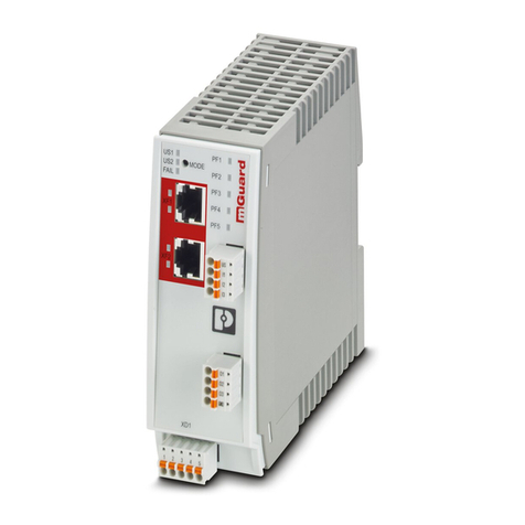
AXL SE PSDI8/3
4 / 84 PHOENIX CONTACT 108928_en_02
3.9 Safety-related system time .................................................................................. 23
3.9.1 Processing time of the input in the event of a safety demand ...............23
3.9.2 Error detection time .............................................................................. 23
3.9.3 Duration of a safety demand ................................................................ 23
3.9.4 Response time of the PROFIsafe system ............................................24
3.10 Process data words............................................................................................. 24
3.11 Programming data/configuration data..................................................................24
4 Mounting and removal .............................................................................................................25
4.1 Assembly instructions..........................................................................................25
4.2 Setting the safety address ...................................................................................26
4.2.1 Address assignment via DIP switch ..................................................... 26
4.3 Mounting the Smart Element ............................................................................... 27
4.4 Removing the Smart Element .............................................................................. 27
4.5 Optional equipment identification ........................................................................ 28
5 Electrical installation ................................................................................................................29
5.1 Installation instructions ........................................................................................ 29
5.2 Cables connected to Smart Elements ................................................................. 30
5.3 Conductor cross sections, and stripping and insertion lengths............................ 31
5.4 Terminal points and associated spring lever........................................................ 33
5.5 Connecting the cables......................................................................................... 34
5.6 Removing cables from the terminal point............................................................. 36
6 Parameterization ......................................................................................................................37
6.1 Parameterization in a PROFIsafe system ............................................................ 37
6.2 Parameterization of the safe inputs...................................................................... 38
6.2.1 Single-channel assignment .................................................................. 39
6.2.2 Two-channel equivalent assignment .................................................... 39
6.2.3 Two-channel non-equivalent assignment ............................................. 41
6.2.4 Symmetry and start inhibit .................................................................... 42
6.2.5 Cross-circuit detection ......................................................................... 44
7 Connection examples of safe inputs ........................................................................................45
7.1 Explanation of the examples................................................................................ 45
7.2 Single-channel assignment of safe inputs ........................................................... 46
7.2.1 Cross-circuit monitoring enabled, supply through assigned
clock output .......................................................................................... 46
7.2.2 Cross-circuit monitoring disabled, supply through a clock output
or external 24 V .................................................................................... 48
7.2.3 Supply through OSSD .......................................................................... 50

