OmniOn Power GPS4827 User manual

Page 1
© Copyright 2023 OmniOn power Inc. All rights reserved. GPS4827 _MAN Rev. 1.3
PRODUCT MANUAL
GPS4827 Innity Power System
User’s Guide
Product Manual
Ordering Code 850022019

Page 2
© Copyright 2023 OmniOn power Inc. All rights reserved. GPS4827 _MAN Rev. 1.3
Notice:
The information, specications, and procedures in this manual are subject to change without notice. OmniOn Power
assumes no responsibility for any errors that may appear in this document.

Page 3
© Copyright 2023 OmniOn power Inc. All rights reserved. GPS4827 _MAN Rev. 1.3
PRODUCT MANUAL
GPS4827 Innity Power System
User’s Guide
Table of Contents
1. Introduction························································································································································5
GPS4827························································································································································································· 5
Customer Service Contacts······················································································································································· 6
2. System Description ···········································································································································7
Overview·························································································································································································· 7
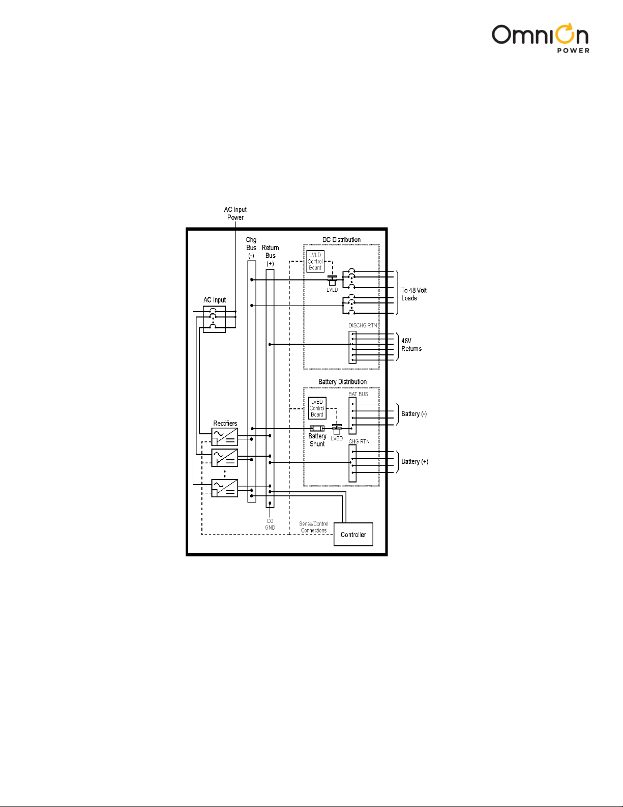
Architecture ··················································································································································································· 9
3. Galaxy Millennium II Controller·······················································································································13
4. Rectiers ···························································································································································17
NE050AC48ATEZ·········································································································································································17
5. AC Input Panels················································································································································21
Overview·························································································································································································21
6. Battery Connection Panels····························································································································· 23
7. DC Distribution Panels····································································································································25
Function······················································································································································································· 25
8. External Return Bars········································································································································31
Overview·························································································································································································31
9. Millennium II Controller Operation················································································································ 35
Controller Connections ···························································································································································· 37
Installing Circuit Packs·····························································································································································38
Thermal Probes···········································································································································································42
USB Interface···············································································································································································43
Local Port······················································································································································································43
Wiring Alarm Outputs ······························································································································································43
Wiring Alarm and Control Inputs··········································································································································46
Fuses·······························································································································································································50
Front Panel Display·····································································································································································51
Controller Defaults·····································································································································································54
Controller Display Menu Maps················································································································································61
10. Acceptance Testing········································································································································· 71
Introduction··················································································································································································71
Tools and Test Equipment························································································································································71
Test Precautions ··········································································································································································71
Test Sequences ···········································································································································································72

Page 4
© Copyright 2023 OmniOn power Inc. All rights reserved. GPS4827 _MAN Rev. 1.3
11. Circuit Boards ···················································································································································· 81
Overview ·······················································································································································································81
12. Specications·················································································································································83
Rectier ························································································································································································85
13. Safety······························································································································································87
Safety Statements····································································································································································87
14. Maintenance and Replacement ···················································································································89
Requirements ···········································································································································································89
Rectier Installation and Replacement Procedures ·····································································································89
15. Troubleshooting Procedure·························································································································· 91
Preliminary ···················································································································································································91
Troubleshooting Procedure···················································································································································92
16. Product Warranty·············································································································································93
17. Revision ····························································································································································95

Page 5
© Copyright 2023 OmniOn power Inc. All rights reserved. GPS4827 _MAN Rev. 1.3
1. Introducon
GPS4827
OmniOn Power developed the Galaxy Power System GPS 4827 to support -48 volt telecommunications powering
solutions in worldwide markets. The GPS 4827 combines 50-ampere, fan-cooled, switchmode rectiers,
microprocessor control technologies, battery and load disconnect/reconnect options, and a comprehensive line of fuse
and circuit breaker dc distribution options in a modular front-access design. This modularity ensures easy access,
simplied installation and maintenance, and allows the system to expand in capacity as power needs grow.
With 1,800-ampere maximum capacity, distribution exibility, and universal ac input capability, the GPS 4827 supports
switching, transmission, and wireless applications in central ofce locations and environmentally controlled remote
sites (huts or vaults).
The main emphasis of this manual is to provide a general product description that will familiarize the user with the
main components of the system and to provide guidelines for the basic maintenance of this Galaxy Power System.
The Millennium controller provides many advanced functions and features, including;
• Alarm Detection, Identication, and Reporting
• System and Component Status
• System and Feature Conguration
• System Alarm Thresholds
• Battery Management (Slope Thermal Compensation/Recharge Current Limit)
• Battery discharge testing
• Reserve Time Prediction
• Float/Boost Mode Control
• Low Voltage Disconnect Management
• Remote Access Control And Multiple Level Password Security
• History
• Statistics

Page 6
© Copyright 2023 OmniOn power Inc. All rights reserved. GPS4827 _MAN Rev. 1.3
Customer Service Contacts
Customer Service, Customer Training, Technical Support, Product Repair and Return, and Warranty Service
For customers in the United States, Canada, Puerto Rico, and the US Virgin Islands,
please dial 1-877-546-3243 (877 OmniOn) or for all other countries, please call 1-972-244-9288. This number is staffed
from 7:00 am to 5:00 pm USA Central Time Zone (GMT -6), Monday through Friday, on normal business days. At other
times, this number is still available, but for emergencies only. Services provided include initiating the spare parts
procurement process, ordering documents, product warranty administration, and providing other product and service
information.
For other customers worldwide the 800 number may be accessed after rst dialing the Direct country code for the
country where the call is originating, or you may contact your local eld support center or your sales representative to
discuss your specic needs.
On-Line Power Systems Product Manuals and Software
Power Systems product manuals and software are available on-line. Software includes Easy View and SNMP MIB.

Page 7
© Copyright 2023 OmniOn power Inc. All rights reserved. GPS4827 _MAN Rev. 1.3
2. System Descripon
Overview
Block Diagram
A basic block diagram of the Galaxy Power System 4827 is shown in Figure 2-1. It illustrates the arrangement and
interconnection of the system components from the ac input to the dc output.
Figure 2-1 Block Diagram of the GPS4827
System Components
The power system accepts alternating current from the commercial utility or a standby ac power source and recties it to
produce dc power for the using equipment. The system’s control and alarm functions interact with the rectiers and the
ofce. In addition, the system provides overcurrent protection and charge, discharge, and distribution facilities. Battery
reserve is connected in parallel and automatically provides a source of dc power if the commercial or standby ac fails.
Battery reserve can be engineered to supply dc power for a specic period of time. In normal practice, battery capacity is
sized to provide 3 to 8 hours of reserve time.

Page 8
© Copyright 2023 OmniOn power Inc. All rights reserved. GPS4827 _MAN Rev. 1.3
AC Input: connects the commercial and/or standby ac power sources to the rectiers within the system and provides
overcurrent protection. In some applications the ac service is wired directly to the rectiers and overcurrent protection is
provided at the service panel.
Rectiers: convert an ac source voltage into the dc voltage level required to charge and oat the batteries and to power the
using equipment.
Controller: provides the local and remote control, monitoring, and diagnostic functions required to administer the power
system.
Batteries: provide energy storage for an uninterrupted power feed to the using equipment during loss of ac input or rectier
failure.
DC Distribution Panel: provides overcurrent protection, connection points for the using equipment, and bus bars used to
interconnect the rectiers, batteries, and dc distribution.
Battery Connection Panel: provides connection points for the battery strings through battery disconnect fuses or contactors
and current monitoring shunts.

Page 9
© Copyright 2023 OmniOn power Inc. All rights reserved. GPS4827 _MAN Rev. 1.3
Architecture
Congurations
The GPS 4827 is a 7-foot cabinet that can provide up to 1800 amps of DC power in single or multiple cabinets. Shown
in Figures 2-2, 2-3 and 2-4.
Cabinets can contain ac distribution, dc distribution, a battery connection panel, rectiers, and a system controller.
Cabinets can also be ordered as rectier only or distribution only cabinets.
Illustrations
Figure 2-3 shows how supplemental cabinets may be added to grow the system for more distribution. The rectier
output buses are interconnected to permit the cabinet to share current and ensure common voltage references for all
system rectiers. The total system ampacities must not exceed 1800A.
Figure 2-2 Cabinet schematic

Page 10
© Copyright 2023 OmniOn power Inc. All rights reserved. GPS4827 _MAN Rev. 1.3
Figure 2-3 Schematic of Two-cabinet System Architecture 1800A Maximum per system.
Shared DC Power
Battery String
To Loads
AC
AC
Ground Cabinet
Ground
Shared DC Power AC
Battery String
Battery String
AC
System (CO)
Ground
Cabinet
Ground
AC
Ground
Cabinet
Ground
AC
Ground
To Loads
To Loads
Controller
Rectier
Battery
Distribution
Cabinet
Rectier
Battery
Distribution
Cabinet
Rectier
Battery
Distribution
Cabinet

Page 11
© Copyright 2023 OmniOn power Inc. All rights reserved. GPS4827 _MAN Rev. 1.3
Figure 2-5 GPS4827 Six shelf cabinet with door removed
Rectier Shelves 3 ,
6, or 9
Miscellaneous DC
Distribution Panels
AC Panel Circuit Breakers or
Terminal strip

Page 12
© Copyright 2023 OmniOn power Inc. All rights reserved. GPS4827 _MAN Rev. 1.3
This page intentionally left blank

Page 13
© Copyright 2023 OmniOn power Inc. All rights reserved. GPS4827 _MAN Rev. 1.3
3. Galaxy Millennium II Controller
Overview
Introduction
The GPS 4827 comes equipped with the Galaxy Millennium II Controller. This section describes the controller operation
and detailed information about the features of the front panel keys, LEDs, and display.
The Galaxy Millennium II Controller provides advanced local and remote monitoring and data acquisition features. The
controller monitors system parameters; such as, system voltage and current, and components; such as rectiers, and
distribution circuits. The controller reports the status and issues appropriate alarms in the event a failure occurs.
Each cabinet is equipped with a bay interface card (BIC). The BIC acts as an interface to the cabinet control and alarm
signals.
User Interface and Display
The Millennium II’s primary user interface is a backlit LCD front panel display that can be viewed in English or Spanish,
two rows of LEDs, an array of pushbutton keys, and a pair of test jacks.
Default Display
The default display shows basic system status; system voltage, load current, and plant state. The controller returns to
this display approximately three minutes after a key is pressed. The information on the screen is updated
automatically approximately every two seconds.
The default screen displays the following: The rst line shows the number of alarms and warnings present in the
system, the date, and the time. The next two lines show the system voltage and the system load. The last line shows
the system mode, which can be one of the following:
• FLOAT
• BOOST
• STC (Slope Thermal Compensation)
• BATT TEST
Figure 3-1 illustrates the front panel.

Page 14
© Copyright 2023 OmniOn power Inc. All rights reserved. GPS4827 _MAN Rev. 1.3
LEDs
Two rows of LEDs show the source and severity of various alarms. An alarm lights one status LED and one or more
alarm LEDs. If more than one alarm LED lights, the status LED that lights will indicate the most severe active alarm.
• The rst row includes four LEDs, labeled Alarm Status. They indicate the severity of the reported alarm:
• Critical
• Major
• Minor
• Normal
The Battery on Discharge LED is also in this row.
• The second row has seven LEDs, labeled Equipment Status. They indicate the source of the alarm:
• AC System
• Battery
• Controller
• Distribution
• Rectier
• Remote Modules
The Modem LED illuminates when the internal modem is in use.
Test Jacks
A pair of test jacks allows direct measurement of the dc bus sense voltage being monitored by the controller.
Pushbutton Keys
A group of pushbutton keys below the backlit LCD display provides the primary user interface with the controller.
These keys are used singly or in combination to navigate through the controller’s menus.
The following is a general description of the pushbutton keys:
• ESCAPE: Return to the immediate higher level menu.
• HELP: Displays limited on-line help information.
• MENU: View the MAIN menu.
• ENTER: Select a menu item.
• Up arrow: Moves the cursor up one line.
• Down arrow: Moves the cursor down one line.
• Left arrow: Moves the cursor left one eld.
• Right arrow: Moves the cursor right one eld.
• + and -: Increase or decrease parameter values.
• Lamp test: Tests the controller’s circuit board LEDs and front panel LEDs. It will also test the Indicators of serially
connected rectiers.

Page 15
© Copyright 2023 OmniOn power Inc. All rights reserved. GPS4827 _MAN Rev. 1.3
Access Panel
A rubber ap can be opened to access the local port connector. The DB-9 local port connector supports standard
RS232 serial communication. Refer to the Galaxy Millennium II Controller product manual for additional details on port
conguration and isolation.

Page 16
© Copyright 2023 OmniOn power Inc. All rights reserved. GPS4827 _MAN Rev. 1.3
Reference Material
Controller Product Manuals
A The Galaxy Millennium Controller product manual (Select Code 167-792-180) is furnished with every GPS 4827. Refer
to this manual for information regarding conguration and operation.
RPM System Product Manual
Refer to the Galaxy Remote Peripheral Monitoring System product manual (Select Code 167-790-063) for additional
information regarding module operation.

Page 17
© Copyright 2023 OmniOn power Inc. All rights reserved. GPS4827 _MAN Rev. 1.3
4. Recers
NE050AC48ATEZ
Overview
The NE050AC48ATEZ Series rectier (50A) operates from single-phase ac service with a phase-to-phase voltage within
the range of 95 to 275Vac.
The rectiers are shipped separately from the cabinets for quick and straightforward installation into rectier shelves at
the site. Interconnections to ac input, dc output, and control signals occur automatically during insertion. No settings
or adjustments to potentiometers are necessary.
The NE050AC48ATEZ rectiers are UL Recognized for both the U. S. and Canada, comply with UL1950 (Information
Technology Equipment), and meet EN60950 requirements.
Front Panel Display
Status Indicators
Three LEDs on the rectier’s faceplate indicate the rectier’s condition.
• The Norm LED is green and is lit when the rectier has AC input present and is working properly.
• The ACF LED is amber and is lit when there is no AC input present to the rectier.
• The Fail LED is red and is lit if there is a failure in the rectier.
Lamp Test
To test the LEDs on the rectier front panel, press the Lamp Test button on the controller.

Page 18
© Copyright 2023 OmniOn power Inc. All rights reserved. GPS4827 _MAN Rev. 1.3
Features
Output Current “Walk-in”
This circuit controls the time (up to eight seconds) required for the rectier to reach normal operating conditions after
it is turned on. This feature minimizes the starting surge on the customer's power source.
Output Protection
Rectier is equipped with an internal fuse for plant protection if a fault occurs in a rectier.
Electronic Current Limit
When the output current tends to increase above the current limit set point, the current limit circuit overrides the
voltage regulating signal and safely limits the output current of the rectier, thus preventing damage to itself or the
load.
High Voltage Shutdown (HVSD)
The rectier senses the voltage at its output terminals. If this voltage is too high, the rectier will shut down to prevent
the high voltage from damaging itself or the load.
Restart
Upon shutdown, the rectier will attempt to restart. The rectier will also accept a restart command from the
controller for a remote restart. The rectier will attempt to restart three times before issuing a rectier fail alarm to the
controller.
Fan Alarm and Control
The rectier contains a cooling fan. The fan’s speed, which is based on ambient temperature and output power level, is
lowered during low-load and low-temperature conditions to minimize audible noise and maximize fan life.
Thermal Alarm
The rectier senses the internal operating temperature and will issue a thermal alarm if the internal temperature
exceeds a safe operating level. Ambient temperatures above the maximum rating will result in a rectier shutdown
and the issuing of a thermal alarm (TA).
Autonomous Operation
Rectiers will continue to power the load if the controller fails or if communication is lost.
Controller Communications Alarm
When communications between the rectier and controller are interrupted, the rectier continues to operate and the
red Fail LED on the rectier blinks.

Page 19
© Copyright 2023 OmniOn power Inc. All rights reserved. GPS4827 _MAN Rev. 1.3
Connectorized
The rectiers provide the controller with a full complement of status and alarm signals. The rectier status and alarm
signals, ac input, and dc output are all connectorized for easy installation and maintenance. System connections are
made when the rectier is plugged into the shelf. No additional connections are required.
“Forced” Load Sharing
Internal rectier circuitry will allow rectiers to share load in the event communication to the controller is lost or the
controller malfunctions.

Page 20
© Copyright 2023 OmniOn power Inc. All rights reserved. GPS4827 _MAN Rev. 1.3
This page intentionally left blank
Table of contents
Other OmniOn Power Power Supply manuals