B&R Industries MAPPT-ENG User manual

1
Power Panel T-series
User's Manual
Version: 0.30 Preliminary (September 2014)
Model no.: MAPPT-ENG
All information contained in this manual is current as of its creation/publication. B&R reserves the right to change
the contents of this manual without notice. The information contained herein is believed to be accurate as of
the date of publication; however, Bernecker + Rainer Industrie-Elektronik Ges.m.b.H. makes no warranty, ex-
pressed or implied, with regard to the products or documentation contained within this manual. In addition,
Bernecker + Rainer Industrie-Elektronik Ges.m.b.H. shall not be liable for any incidental or consequential damages
in connection with or arising from the furnishing, performance or use of the product(s) in this documentation. Soft-
ware names, hardware names and trademarks are registered by their respective companies.

Table of contents
2 Power Panel T-Series User's Manual V 0.30 Preliminary
Chapter 1 General information................................................................................... 4
1 Manual history....................................................................................................................................................4
2 Safety notices.....................................................................................................................................................4
2.1 Introduction................................................................................................................................................... 4
2.2 Intended use.................................................................................................................................................4
2.3 Protection against electrostatic discharge....................................................................................................4
2.3.1 Packaging................................................................................................................................................5
2.3.2 Guidelines for proper ESD handling.......................................................................................................5
2.4 Transport and storage..................................................................................................................................5
2.5 Installation.....................................................................................................................................................5
2.6 Operation...................................................................................................................................................... 6
2.6.1 Protection against touching electrical parts............................................................................................6
2.6.2 Environmental conditions - Dust, humidity, aggressive gases............................................................... 6
2.6.3 Viruses and dangerous programs.......................................................................................................... 6
2.7 Organization of safety notices......................................................................................................................6
Chapter 2 T-Series....................................................................................................... 7
1 System features................................................................................................................................................. 7
1.1 Compact solution..........................................................................................................................................7
1.2 Simple programming.................................................................................................................................... 7
1.3 Power Panel T30..........................................................................................................................................7
1.4 Flexibility....................................................................................................................................................... 8
1.5 Order number key........................................................................................................................................ 9
2 T-Series............................................................................................................................................................ 10
2.1 Selecting a Power Panel............................................................................................................................10
2.2 General technical data............................................................................................................................... 10
2.3 Overview..................................................................................................................................................... 11
2.3.1 Overview - 6PPT30.043x......................................................................................................................11
2.3.2 Overview - 6PPT30.057x......................................................................................................................11
2.3.3 Overview - 6PPT30.070x......................................................................................................................11
2.3.4 Overview - 6PPT30.101x......................................................................................................................12
2.3.5 Interfaces...............................................................................................................................................12
2.4 6PPT30.xxxx-20x........................................................................................................................................13
2.4.1 6PPT30.043x-20x..................................................................................................................................13
2.4.2 6PPT30.057x-20x..................................................................................................................................16
2.4.3 6PPT30.070x-20x..................................................................................................................................19
2.4.4 6PPT30.101x-20x..................................................................................................................................22
2.4.5 Ethernet LEDs.......................................................................................................................................25
2.4.6 Temperature/Humidity diagram.............................................................................................................26
2.4.7 Connection elements............................................................................................................................ 28
2.4.8 Dimensions............................................................................................................................................30
Chapter 3 Installation.................................................................................................38
1 Installation instructions.....................................................................................................................................38
2 Mounting orientation.........................................................................................................................................40
3 Grounding.........................................................................................................................................................40
4 Configuration - Possible operating modes...................................................................................................... 41
5 Touch screen calibration.................................................................................................................................. 41
Chapter 4 Standards and certifications................................................................... 42
1 Applicable European directives........................................................................................................................42
2 Overview of standards..................................................................................................................................... 42
3 International certifications................................................................................................................................ 42
Chapter 5 Accessories.............................................................................................. 43
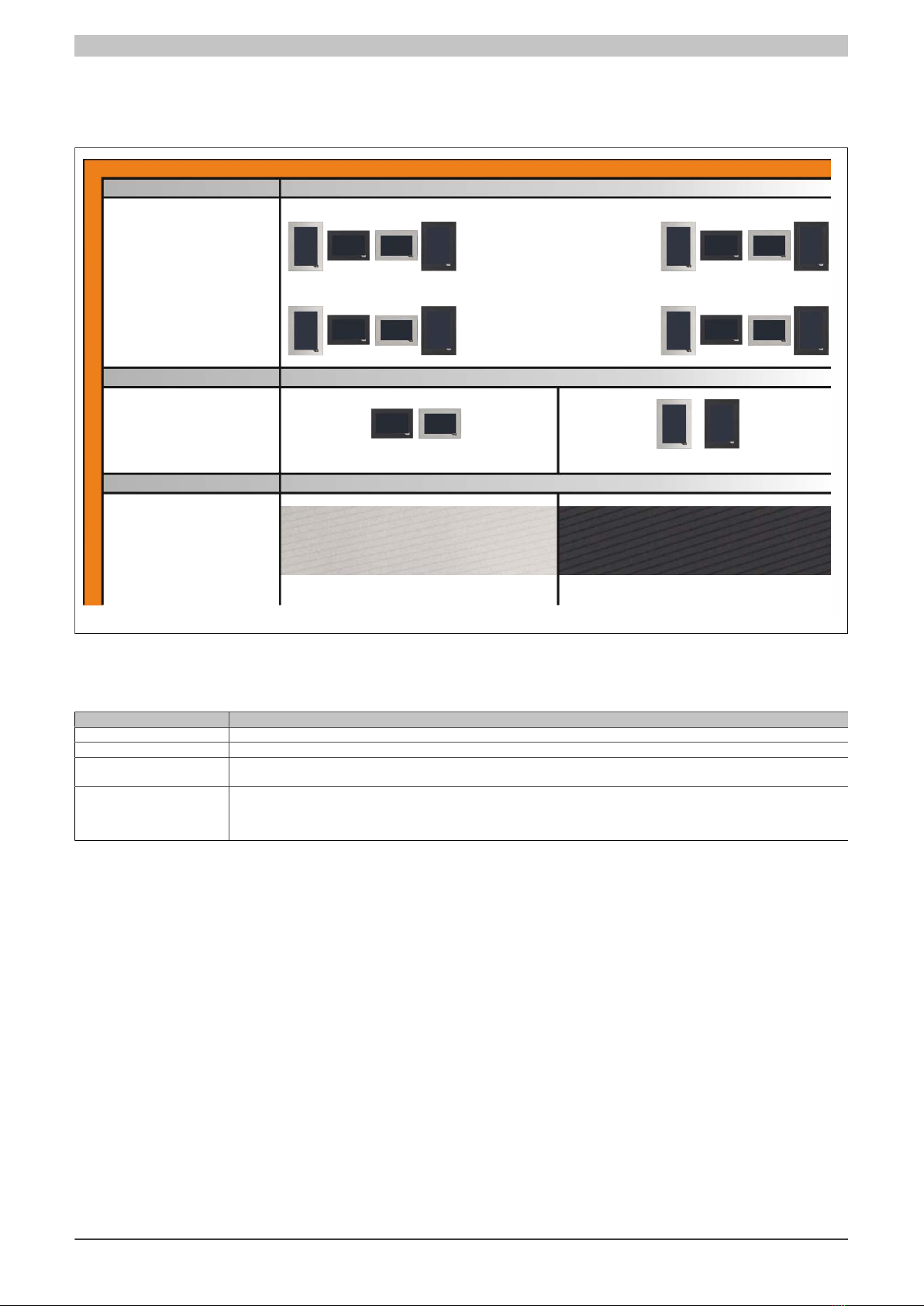
1 T-Series overview............................................................................................................................................ 43
2 TB102 2-pin power supply connector..............................................................................................................44

Table of contents
Table of contents
Power Panel T-Series User's Manual V 0.30 Preliminary 3
2.1 Order data.................................................................................................................................................. 44
2.2 Technical data............................................................................................................................................ 44
3 Data storage media......................................................................................................................................... 44
4 Cable accessories............................................................................................................................................44
Chapter 6 Maintenance..............................................................................................45
1 Cleaning........................................................................................................................................................... 45
2 Screen burn-in on LCD/TFT monitors............................................................................................................. 45
Chapter 7 Technical information.............................................................................. 46
1 Panel membrane..............................................................................................................................................46
2 Viewing angles.................................................................................................................................................46

General information • Safety notices
4 Power Panel T-Series User's Manual V 0.30 Preliminary
Chapter 1 • General information
Information:
B&R keeps the printed version of user's manuals as current as possible. If a newer version of the
user's manual is available, it can always be downloaded in electronic form (PDF) from the B&R website
www.br-automation.com.
1 Manual history
Version Date Comment
0.10 August 2014 First edition
0.20 September 2014 Updated "Technical data" and "Connection elements"
0.30 September 2014 Updated "Technical data", "Temperature/Humidity diagram", "Installation instructions" & "Mounting orientation"
Table 1: Manual history
2 Safety notices
2.1 Introduction
Programmable logic controllers (PLCs), operating and monitoring devices (industrial PCs, Power Panels, Mobile
Panels, etc.), as well as the B&R uninterruptible power supplies have been designed, developed or manufactured
for conventional use in industry. They were not designed, developed and manufactured for any use involving
serious risks or hazards that could lead to death, injury, serious physical damage or loss of any kind without the
implementation of exceptionally stringent safety precautions. In particular, such risks and hazards include the use of
these devices to monitor nuclear reactions in nuclear power plants, their use in flight control or flight safety systems
as well as in the control of mass transportation systems, medical life support systems or weapons systems.
When using programmable logic controllers or operating/monitoring devices as control systems together with a Soft
PLC (e.g. B&R Automation Runtime or comparable product) or Slot PLC (e.g. B&R LS251 or comparable product),
safety precautions relevant to industrial control systems (e.g. the provision of safety devices such as emergency
stop circuits, etc.) must be observed in accordance with applicable national and international regulations. The same
applies for all other devices connected to the system, e.g. drives.
All tasks such as the installation, commissioning and servicing of devices are only permitted to be carried out by
qualified personnel. Qualified personnel are those familiar with the transport, mounting, installation, commissioning
and operation of devices who also have the appropriate qualifications (e.g. IEC 60364). National accident preven-
tion regulations must be observed.
The safety notices, connection descriptions (type plate and documentation) and limit values listed in the technical
data are to be read carefully before installation and commissioning and must be observed.
2.2 Intended use
Electronic devices are never completely failsafe. If the programmable control system, operating/monitoring device
or uninterruptible power supply fails, the user is responsible for ensuring that other connected devices, e.g. motors,
are brought to a secure state.
2.3 Protection against electrostatic discharge
Electrical components that can be damaged by electrostatic discharge (ESD) must be handled accordingly.

General information • Safety notices
Chapter 1
General information
Power Panel T-Series User's Manual V 0.30 Preliminary 5
2.3.1 Packaging
•Electrical components with a housing
… do not require special ESD packaging, but must be handled properly (see "Electrical components with
a housing" on page 5).
•Electrical components without a housing
…are protected by ESD-suitable packaging.
2.3.2 Guidelines for proper ESD handling
Electrical components with a housing
•Do not touch the contacts of connectors on the device (bus data contacts)
•Do not touch the connector contacts on connected cables.
•Do not touch the contact tips on circuit boards.
Electrical components without a housing
The following applies in addition to the points listed under "Electrical components with a housing":
•Any persons handling electrical components or devices with installed electrical components must be
grounded.
•Components may only be touched on their narrow sides or front plate.
•Components should always be stored in a suitable medium (ESD packaging, conductive foam, etc.).
Information: Metallic surfaces are not suitable storage surfaces!
•Components should not be subjected to electrostatic discharge (e.g. through the use of charged plastics).
•Ensure a minimum distance of 10 cm from monitors and TV sets.
•Measurement devices and equipment must be grounded.
•Measurement probes on potential-free measurement devices must be discharged on sufficiently grounded
surfaces before taking measurements.
Individual components
•ESD protective measures for individual components are thoroughly integrated at B&R (conductive floors,
footwear, arm bands, etc.).
•These increased ESD protective measures for individual components are not necessary for customers
handling B&R products.
2.4 Transport and storage
During transport and storage, devices must be protected against undue stress (mechanical loads, temperature,
humidity, aggressive atmospheres, etc.).
Devices contain components sensitive to electrostatic charges that can be damaged by inappropriate handling. It
is therefore necessary to provide the required protective measures against electrostatic discharge when installing
or removing these devices (see "Protection against electrostatic discharge" on page 4).
2.5 Installation
•Installation must be performed according to this documentation using suitable equipment and tools.
•Devices may only be installed by qualified personnel without voltage applied.
•General safety guidelines and national accident prevention regulations must be observed.
•Electrical installation must be carried out according to applicable guidelines (e.g. line cross sections, fuses,
protective ground connections).
•Take the necessary steps to protect against electrostatic discharges ().

General information • Safety notices
6 Power Panel T-Series User's Manual V 0.30 Preliminary
2.6 Operation
2.6.1 Protection against touching electrical parts
To operate programmable logic controllers, operating/monitoring devices or uninterruptible power supplies, it is
necessary for certain parts to carry dangerous voltage levels over 42 VDC. Touching one of these parts can result
in a life-threatening electric shock. This could lead to death, severe injury or damage to equipment.
Before turning on the programmable logic controller, operating/monitoring devices or the uninterruptible power
supply, the housing must be properly grounded (PE rail). Ground connections must be established even when
testing or operating operating/monitoring devices or the uninterruptible power supply for a short time!
Before turning the device on, all parts that carry voltage must be securely covered. During operation, all covers
must remain closed.
2.6.2 Environmental conditions - Dust, humidity, aggressive gases
The use of operating/monitoring devices (e.g. industrial PCs, Power Panels, Mobile Panels, etc.) and uninterruptible
power supplies in very dusty environments should be avoided. Dust collection on the devices can affect functionality
and may prevent sufficient cooling, especially in systems with active cooling systems (fans).
The presence of aggressive gases can also lead to malfunctions. When combined with high temperature and
humidity, aggressive gases – e.g. with sulfur, nitrogen and chlorine components – can induce chemical reactions
that can damage electronic components very quickly. Signs of the presence of aggressive gases are blackened
copper surfaces and cable ends on existing equipment.
For operation in dusty or humid conditions, correctly installed (e.g. cutout installations) operating/monitoring devices
like the Automation Panel or Power Panel are protected on the front. The back of all devices must be protected
from dust and humidity and cleaned at suitable intervals.
2.6.3 Viruses and dangerous programs
This system is subject to potential risk each time data is exchanged or software is installed from a data medium
(e.g. diskette, CD-ROM, USB flash drive, etc.), a network connection or the Internet. The user is responsible for
assessing these dangers, implementing preventive measures such as virus protection programs, firewalls, etc. and
making sure that software is only obtained from trusted sources.
2.7 Organization of safety notices
Safety notices in this manual are organized as follows:
Safety notice Description
Danger! Disregarding these safety guidelines and notices can be life-threatening.
Caution! Disregarding these safety guidelines and notices can result in severe injury or substantial damage to equipment.
Warning! Disregarding these safety guidelines and notices can result in injury or damage to equipment.
Information: This information is important for preventing errors.
Table 2: Organization of safety notices

T-Series • System features
Chapter 2
T-Series
Power Panel T-Series User's Manual V 0.30 Preliminary 7
Chapter 2 • T-Series
1 System features
B&R has added the Power Panel T-Series to its Power Panel family. The Power Panel T30 terminal is equipped
with an embedded browser and can even be used as a VNC client. The terminal series has 2 Ethernet and 2 USB
interfaces, as well as various configuration options.
Figure 1: T-Series
1.1 Compact solution
Power Panels have an extremely compact design, minimal installation depth and an intelligent cable outlet arrange-
ment, making them easy-to-mount space savers. And because they have no hard disks, fans or batteries, they
are also maintenance-free. The panel front provides IP65 protection, which makes these devices extremely well-
suited for harsh industrial environments.
1.2 Simple programming
Full integration of the HMI application in the Automation Studio automation software goes without saying. The same
is true for programming in all of the IEC languages offered by B&R as well as Automation Basic and ANSI C.
1.3 Power Panel T30
The Power Panel T30 is purely a visualization device that can be operated in 2 different modes. On one hand, it
operates as a web browser device using standard technology (frameless full screen mode). On the other hand,
the terminal can also be used optimally with Visual Components.

T-Series • System features
8 Power Panel T-Series User's Manual V 0.30 Preliminary
Figure 2: Power Panel T30
1.4 Flexibility
The Power Panel T-Series is available in 4 different display sizes.
•4.3" display
•5.7" display
•7.0" display
•10.1" display
A touch button is integrated in the panel overlay at the lower right corner of the display. This element can be
incorporated as an elegant feature of the HMI application for quick navigation or easy access to the home screen
or help system.
The option to choose between portrait and landscape format adds even more flexibility to the machine layout. It
is easy to switch between panel models depending on machine requirements. When it comes to color, users can
select between two pinstripe options: anthracite gray or aluminum white.
Regardless of model, size and color, what all the devices have in common are a shallow installation depth and
a minimized border width. Yet, even with the reduced dimensions, no compromises were made with regard to
mounting stability or seal integrity.

T-Series • System features
Chapter 2
T-Series
Power Panel T-Series User's Manual V 0.30 Preliminary 9
1.5 Order number key
0
4
3
4.3"
F
K
VGA (640 x 480) landscape
WQVGA (242 x 480) portrait
Product area
Browser device
Product family
Power Panel
Model
T-Series
Model (processor)
ARM low performance
Display size
5.7"
7.0"
10.1"
Resolution
WVGA (800 x 480) landscape
WQVGA (480 x 272) landscape
WSVGA (1024 x 600) landscape
VGA (480 x 640) portrait
WVGA (480 x 800) portrait
WSVGA (600 x 1024) portrait
Display / touch screen technology and memory
Standard memory
TFT color + analog resistive touch screen
Interfaces on option board
No option board
Standard panel overlay variants
Aluminum white
Anthracite
Customer-specific
Custom panel overlay
Sequential number [F][0..Z][0..Z][0..Z]
Customization going beyond custom overlay
Sequential number [C][0..Z][0..Z][0..Z]
Base model
Derivative: Sequential number [0]
Standard variants
Overlays and custom variants
Follow-up model variants or I/O configuration
X X X X X X . X X X X - X X X X X X
6
P P
T
3 0
0 5 7
0 7 0
1 0 1
2
3
G
L
M
N
2
0
W
B
F . . .
C . . .
- 0 1
Figure 3: Order number key

T-Series • T-Series
10 Power Panel T-Series User's Manual V 0.30 Preliminary
2 T-Series
2.1 Selecting a Power Panel
Resolution
Display size
4.3"
7"
10.1"
Panel overlay
The Power Panel T-Series is available in 4
different display sizes:
Configuration
6PPT30.043x-20x
5.7" variant
7.0" variant
10.1" variant
The option to choose between portrait and
landscape format adds even more flexibility to
Aluminium white pinstripe
Anthracite gray pinstripe
6PPT30.0573-20x
6PPT30.0702-20x 6PPT30.101G-20x
6PPT30.057L-20x
6PPT30.070M-20x 6PPT30.101N-20x
The pinstripe design is available in
aluminium white or anthracite gray.
Landscape
Portrait
6PPT30.0573-20W
6PPT30.0702-20W
6PPT30.101G-20W
6PPT30.057L-20W
6PPT30.070M-20W
6PPT30.101N-20W
6PPT30.0573-20B
6PPT30.0702-20B
6PPT30.101G-20B
6PPT30.057L-20B
6PPT30.070M-20B
6PPT30.101N-20B
4.3" variant
5.7"
6PPT30.070x-20x 6PPT30.101x-20x
6PPT30.057x-20x
6PPT30.043F-20x 6PPT30.043K-20x
6PPT30.043F-20W
6PPT30.043F-20W
6PPT30.043K-20B
6PPT30.043K-20B
the machine layout.
Figure 4: Selecting a Power Panel
2.2 General technical data
Name Description
Processor ARM Cortex A8 600 MHz
Memory 256 MB DDRAM
Interfaces 2 Ethernet interfaces 10/100BASE-T
2 USB 2.0 ports
Other IP65 protection (front side)
Temperature range from 0 to 50°C
Fanless
Power supply 8 to 32 VDC
Table 3: Power Panel T-Series - General technical data

T-Series • T-Series
Chapter 2
T-Series
Power Panel T-Series User's Manual V 0.30 Preliminary 11
2.3 Overview
2.3.1 Overview - 6PPT30.043x
Model number 6PPT30.043F-20W 6PPT30.043F-20B 6PPT30.043K-20W 6PPT30.043K-20B
Figure
Display TFT color
Resolution WQVGA
Display size 4.3"
Touch screen Analog resistive
Format Landscape Portrait
Color Aluminum white Anthracite Aluminum white Anthracite
Page 13
Table 4: Overview - 6PPT30.043x
2.3.2 Overview - 6PPT30.057x
Model number 6PPT30.0573-20W 6PPT30.0573-20B 6PPT30.057L-20W 6PPT30.057L-20B
Figure
Display TFT color
Resolution VGA
Display size 5.7"
Touch screen Analog resistive
Format Landscape Portrait
Color Aluminum white Anthracite Aluminum white Anthracite
Page 16
Table 5: Overview - 6PPT30.057x
2.3.3 Overview - 6PPT30.070x
Model number 6PPT30.0702-20W 6PPT30.0702-20B 6PPT30.070M-20W 6PPT30.070M-20B
Figure
Display TFT color
Table 6: Overview - 6PPT30.070x

T-Series • T-Series
12 Power Panel T-Series User's Manual V 0.30 Preliminary
Model number 6PPT30.0702-20W 6PPT30.0702-20B 6PPT30.070M-20W 6PPT30.070M-20B
Resolution WVGA
Display size 7.0"
Touch screen Analog resistive
Format Landscape Portrait
Color Aluminum white Anthracite Aluminum white Anthracite
Page 19
Table 6: Overview - 6PPT30.070x
2.3.4 Overview - 6PPT30.101x
Model number 6PPT30.101G-20W 6PPT30.101G-20B 6PPT30.101N-20W 6PPT30.101N-20B
Figure
Display TFT color
Resolution WSVGA
Display size 10.1"
Touch screen Analog resistive
Format Landscape Portrait
Color Aluminum white Anthracite Aluminum white Anthracite
Page 22
Table 7: Overview - 6PPT30.101x
2.3.5 Interfaces
Model number 6PPT30.xxxx-20x
Figure
Ethernet interfaces
10/100BASE-T
2
USB 2.0 interfaces 2
Table 8: Interfaces

T-Series • T-Series
Chapter 2
T-Series
Power Panel T-Series User's Manual V 0.30 Preliminary 13
2.4 6PPT30.xxxx-20x
2.4.1 6PPT30.043x-20x
2.4.1.1 6PPT30.043x-20x - Order data
Model number Short description Figure
T30
6PPT30.043F-20W Power Panel T30, 4.3", analog resistive touch screen, 2 Ether-
net interfaces, internal switch, 2 USB 2.0 interfaces, embedded
client software: - VNC client mode - Embedded web browser on
board, landscape format, aluminum white pinstripe
6PPT30.043F-20B Power Panel T30, 4.3", analog resistive touch screen, 2 Ether-
net interfaces, internal switch, 2 USB 2.0 interfaces, embedded
client software: - VNC client mode - Embedded web browser on
board, landscape format, anthracite gray pinstripe
6PPT30.043K-20W Power Panel T30, 4.3", analog resistive touch screen, 2 Ether-
net interfaces, internal switch, 2 USB 2.0 interfaces, embedded
client software: - VNC client mode - Embedded web browser on
board, portrait format, aluminum white pinstripe
6PPT30.043K-20B Power Panel T30, 4.3", analog resistive touch screen, 2 Ether-
net interfaces, internal switch, 2 USB 2.0 interfaces, embedded
client software: - VNC client mode - Embedded web browser on
board, portrait format, anthracite gray pinstripe
Required accessories
Terminal blocks
0TB6102.2010-01 Accessory terminal block, 2-pin (3.81), screw clamp 1.5 mm²
0TB6102.2110-01 Accessory terminal block, 2-pin (3.81), cage clamp, 1.5 mm²
USB accessories
5MMUSB.2048-01 USB 2.0 flash drive, 2048 MB, B&R
5MMUSB.4096-01 USB 2.0 flash drive, 4096 MB, B&R
Table 9: 6PPT30.043F-20W, 6PPT30.043F-20B, 6PPT30.043K-20W, 6PPT30.043K-20B - Order data

T-Series • T-Series
14 Power Panel T-Series User's Manual V 0.30 Preliminary
2.4.1.2 6PPT30.043x-20x - Technical data
Product ID 6PPT30.043F-20W 6PPT30.043F-20B 6PPT30.043K-20W 6PPT30.043K-20B
General information
Cooling Fanless
LEDs Ethernet
B&R ID code 0xE589 0xE58A 0xE58B 0xE58C
Power button No
Reset button No
Buzzer Yes
Electrical isolation
24 VDC - USB No
USB - Ethernet Yes
Ethernet - 24 VDC Yes
Certification
CE Yes
GOST-R Yes
Controller
Operating system T30 image
DRAM 256 MB
Real-time clock No
Processor
Type ARM Cortex A8
Clock frequency 600 MHz
L1 cache 64 kB
L2 cache 256 kB
Flash 512 MB
Cooling Passive
Mode/Node switches No
Interfaces
Switch
Interface A IF1 interface
Interface B IF2 interface
IF1 interface
Type Ethernet
Design 1x RJ45 shielded
Cable length Max. 100 m between 2 stations (segment length)
Max. transfer rate 10/100 Mbit/s
Transmission
Physical interfaces 10BASE-T / 100BASE-TX
Half-duplex Yes
Full-duplex Yes
Autonegotiation Yes
Auto-MDI / MDIX Yes
IF2 interface
Type Ethernet
Design 1x RJ45 shielded
Cable length Max. 100 m between 2 stations (segment length)
Max. transfer rate 10/100 Mbit/s
Transmission
Physical interfaces 10BASE-T / 100BASE-TX
Half-duplex Yes
Full-duplex Yes
Autonegotiation Yes
Auto-MDI / MDIX Yes
IF3 interface
Type USB 2.0
Design Type A
Current load 0.5 A
IF4 interface
Type USB 2.0
Design Type A
Current load 0.1 A
Display
Type TFT color
Display size 4.3"
Colors 16.7 M
Resolution WQVGA, 480 x 272 pixels WQVGA, 272 x 480 pixels
Contrast Typ. 350:1
Viewing angles
Horizontal Direction R / Direction L = typ. 70° Direction R = typ. 45° / Direction L = typ. 65°
Vertical Direction U = typ. 45° / Direction D = typ. 65° Direction U / Direction D = typ. 70°
Table 10: 6PPT30.043F-20W, 6PPT30.043F-20B, 6PPT30.043K-20W, 6PPT30.043K-20B - Technical data

T-Series • T-Series
Chapter 2
T-Series
Power Panel T-Series User's Manual V 0.30 Preliminary 15
Product ID 6PPT30.043F-20W 6PPT30.043F-20B 6PPT30.043K-20W 6PPT30.043K-20B
Backlight
Classification LED
Brightness Typ. 350 cd/m2
Half-brightness time 1) 30.000 h
Touch screen
Type AMT
Technologies Analog resistive
Controller B&R, 12-bit
Transmittance 80% ±3%
Screen rotation Yes
Electrical characteristics
Nominal voltage 8 to 32 VDC
Max. current at nominal voltage 230 mA
Max. power consumption 5.5 W
Operating conditions
EN 60529 protection Back: IP20
Front: IP65
Environmental conditions
Temperature
Operation
Horizontal installation -20 to 60°C
Vertical installation -20 to 60°C
Storage -20 to 60°C
Transport -20 to 60°C
Relative humidity
Operation See humidity diagram
Storage See humidity diagram
Transport See humidity diagram
Mechanical characteristics
Note Order 1x 0TB6102.2010-01 and 1x 0TB6102.2110-01 terminal block separately
Front
Design Aluminum white pinstripe Anthracite gray pinstripe Aluminum white pinstripe Anthracite gray pinstripe
Dimensions
Width 140 mm 96 mm
Height 96 mm 140 mm
Depth 38.3 mm
Table 10: 6PPT30.043F-20W, 6PPT30.043F-20B, 6PPT30.043K-20W, 6PPT30.043K-20B - Technical data
1) At an ambient temperature of 25°C. Reducing the brightness by 50% can result in an approximately 50% increase in the half-brightness time.

T-Series • T-Series
16 Power Panel T-Series User's Manual V 0.30 Preliminary
2.4.2 6PPT30.057x-20x
2.4.2.1 6PPT30.057x-20x - Order data
Model number Short description Figure
T30
6PPT30.0573-20W Power Panel T30, 5.7", analog resistive touch screen, 2 Ether-
net interfaces, internal switch, 2 USB 2.0 interfaces, embedded
client software: - VNC client mode - Embedded web browser on
board, landscape format, aluminum white pinstripe
6PPT30.0573-20B Power Panel T30, 5.7", analog resistive touch screen, 2 Ether-
net interfaces, internal switch, 2 USB 2.0 interfaces, embedded
client software: - VNC client mode - Embedded web browser on
board, landscape format, anthracite gray pinstripe
6PPT30.057L-20W Power Panel T30, 5.7", analog resistive touch screen, 2 Ether-
net interfaces, internal switch, 2 USB 2.0 interfaces, embedded
client software: - VNC client mode - Embedded web browser on
board, portrait format, aluminum white pinstripe
6PPT30.057L-20B Power Panel T30, 5.7", analog resistive touch screen, 2 Ether-
net interfaces, internal switch, 2 USB 2.0 interfaces, embedded
client software: - VNC client mode - Embedded web browser on
board, portrait format, anthracite gray pinstripe
Required accessories
Terminal blocks
0TB6102.2010-01 Accessory terminal block, 2-pin (3.81), screw clamp 1.5 mm²
0TB6102.2110-01 Accessory terminal block, 2-pin (3.81), cage clamp, 1.5 mm²
USB accessories
5MMUSB.2048-01 USB 2.0 flash drive, 2048 MB, B&R
5MMUSB.4096-01 USB 2.0 flash drive, 4096 MB, B&R
Table 11: 6PPT30.0573-20W, 6PPT30.0573-20B, 6PPT30.057L-20W, 6PPT30.057L-20B - Order data

T-Series • T-Series
Chapter 2
T-Series
Power Panel T-Series User's Manual V 0.30 Preliminary 17
2.4.2.2 6PPT30.057x-20x - Technical data
Product ID 6PPT30.0573-20W 6PPT30.0573-20B 6PPT30.057L-20W 6PPT30.057L-20B
General information
Cooling Fanless
LEDs Ethernet
B&R ID code 0xE58D 0xE58E 0xE58F 0xE590
Power button No
Reset button No
Buzzer Yes
Electrical isolation
24 VDC - USB No
USB - Ethernet Yes
Ethernet - 24 VDC Yes
Certification
CE Yes
GOST-R Yes
Controller
Operating system T30 image
DRAM 256 MB
Real-time clock No
Processor
Type ARM Cortex A8
Clock frequency 600 MHz
L1 cache 64 kB
L2 cache 256 kB
Flash 512 MB
Cooling Passive
Mode/Node switches No
Interfaces
Switch
Interface A IF1 interface
Interface B IF2 interface
IF1 interface
Type Ethernet
Design 1x RJ45 shielded
Cable length Max. 100 m between 2 stations (segment length)
Max. transfer rate 10/100 Mbit/s
Transmission
Physical interfaces 10BASE-T / 100BASE-TX
Half-duplex Yes
Full-duplex Yes
Autonegotiation Yes
Auto-MDI / MDIX Yes
IF2 interface
Type Ethernet
Design 1x RJ45 shielded
Cable length Max. 100 m between 2 stations (segment length)
Max. transfer rate 10/100 Mbit/s
Transmission
Physical interfaces 10BASE-T / 100BASE-TX
Half-duplex Yes
Full-duplex Yes
Autonegotiation Yes
Auto-MDI / MDIX Yes
IF3 interface
Type USB 2.0
Design Type A
Current load 0.5 A
IF4 interface
Type USB 2.0
Design Type A
Current load 0.1 A
Display
Type TFT color
Display size 5.7"
Colors 262,000
Resolution VGA, 640 x 480 pixels VGA, 480 x 640 pixels
Contrast Typ. 850:1
Viewing angles
Horizontal Direction R / Direction L = typ. 80°
Vertical Direction U / Direction D = typ. 80°
Table 12: 6PPT30.0573-20W, 6PPT30.0573-20B, 6PPT30.057L-20W, 6PPT30.057L-20B - Technical data

T-Series • T-Series
18 Power Panel T-Series User's Manual V 0.30 Preliminary
Product ID 6PPT30.0573-20W 6PPT30.0573-20B 6PPT30.057L-20W 6PPT30.057L-20B
Backlight
Classification LED
Brightness Typ. 400 cd/m2
Half-brightness time 1) 50,000 h
Touch screen
Type AMT
Technologies Analog resistive
Controller B&R, 12-bit
Transmittance 80% ±3%
Screen rotation Yes
Electrical characteristics
Nominal voltage 8 to 32 VDC
Max. current at nominal voltage 319 mA
Max. power consumption 7.66 W
Operating conditions
EN 60529 protection Back: IP20
Front: IP65
Environmental conditions
Temperature
Operation
Horizontal installation -20 to 60°C
Vertical installation -20 to 60°C
Storage -20 to 60°C
Transport -20 to 60°C
Relative humidity
Operation See humidity diagram
Storage See humidity diagram
Transport See humidity diagram
Mechanical characteristics
Note Order 1x 0TB6102.2010-01 and 1x 0TB6102.2110-01 terminal block separately
Front
Design Aluminum white pinstripe Anthracite gray pinstripe Aluminum white pinstripe Anthracite gray pinstripe
Dimensions
Width 172 mm 140 mm
Height 140 mm 172 mm
Depth 48 mm
Table 12: 6PPT30.0573-20W, 6PPT30.0573-20B, 6PPT30.057L-20W, 6PPT30.057L-20B - Technical data
1) At an ambient temperature of 25°C. Reducing the brightness by 50% can typically result in an approximately 50% increase in the half-brightness time.

T-Series • T-Series
Chapter 2
T-Series
Power Panel T-Series User's Manual V 0.30 Preliminary 19
2.4.3 6PPT30.070x-20x
2.4.3.1 6PPT30.070x-20x - Order data
Model number Short description Figure
T30
6PPT30.0702-20W Power Panel T30, 7", analog resistive touch screen, 2 Ether-
net interfaces, internal switch, 2 USB 2.0 interfaces, embedded
client software: - VNC client mode - Embedded web browser on
board, landscape format, aluminum white pinstripe
6PPT30.0702-20B Power Panel T30, 7", analog resistive touch screen, 2 Ether-
net interfaces, internal switch, 2 USB 2.0 interfaces, embedded
client software: - VNC client mode - Embedded web browser on
board, landscape format, anthracite gray pinstripe
6PPT30.070M-20W Power Panel T30, 7", analog resistive touch screen, 2 Ether-
net interfaces, internal switch, 2 USB 2.0 interfaces, embedded
client software: - VNC client mode - Embedded web browser on
board, portrait format, aluminum white pinstripe
6PPT30.070M-20B Power Panel T30, 7", analog resistive touch screen, 2 Ether-
net interfaces, internal switch, 2 USB 2.0 interfaces, embedded
client software: - VNC client mode - Embedded web browser on
board, portrait format, anthracite gray pinstripe
Required accessories
Terminal blocks
0TB6102.2010-01 Accessory terminal block, 2-pin (3.81), screw clamp 1.5 mm²
0TB6102.2110-01 Accessory terminal block, 2-pin (3.81), cage clamp, 1.5 mm²
USB accessories
5MMUSB.2048-01 USB 2.0 flash drive, 2048 MB, B&R
5MMUSB.4096-01 USB 2.0 flash drive, 4096 MB, B&R
Table 13: 6PPT30.0702-20W, 6PPT30.0702-20B, 6PPT30.070M-20W, 6PPT30.070M-20B - Order data

T-Series • T-Series
20 Power Panel T-Series User's Manual V 0.30 Preliminary
2.4.3.2 6PPT30.070x-20x - Technical data
Product ID 6PPT30.0702-20W 6PPT30.0702-20B 6PPT30.070M-20W 6PPT30.070M-20B
General information
Cooling Fanless
LEDs Ethernet
B&R ID code 0xE591 0xE592 0xE593 0xE594
Power button No
Reset button No
Buzzer Yes
Electrical isolation
24 VDC - USB No
USB - Ethernet Yes
Ethernet - 24 VDC Yes
Certification
CE Yes
GOST-R Yes
Controller
Operating system T30 image
DRAM 256 MB
Real-time clock No
Processor
Type ARM Cortex A8
Clock frequency 600 MHz
L1 cache 64 kB
L2 cache 256 kB
Flash 512 MB
Cooling Passive
Mode/Node switches No
Interfaces
Switch
Interface A IF1 interface
Interface B IF2 interface
IF1 interface
Type Ethernet
Design 1x RJ45 shielded
Cable length Max. 100 m between 2 stations (segment length)
Max. transfer rate 10/100 Mbit/s
Transmission
Physical interfaces 10BASE-T / 100BASE-TX
Half-duplex Yes
Full-duplex Yes
Autonegotiation Yes
Auto-MDI / MDIX Yes
IF2 interface
Type Ethernet
Design 1x RJ45 shielded
Cable length Max. 100 m between 2 stations (segment length)
Max. transfer rate 10/100 Mbit/s
Transmission
Physical interfaces 10BASE-T / 100BASE-TX
Half-duplex Yes
Full-duplex Yes
Autonegotiation Yes
Auto-MDI / MDIX Yes
IF3 interface
Type USB 2.0
Design Type A
Current load 0.5 A
IF4 interface
Type USB 2.0
Design Type A
Current load 0.1 A
Display
Type TFT color
Display size 7"
Colors 16.2 M
Resolution WVGA, 800 x 480 pixels WVGA, 480 x 800 pixels
Contrast Typ. 600:1
Viewing angles
Horizontal Direction R / Direction L = typ. 60° Direction R / Direction L = typ. 70°
Vertical Direction U / Direction D = typ. 70° Direction U / Direction D = typ. 60°
Table 14: 6PPT30.0702-20W, 6PPT30.0702-20B, 6PPT30.070M-20W, 6PPT30.070M-20B - Technical data
Table of contents
Popular Industrial Monitor manuals by other brands

Pro-face
Pro-face Xycom 3015 Hardware guide

Contec
Contec FPD-M21VT-AC user manual

MedLux
MedLux Wall GPI installation manual

Hope Industrial Systems
Hope Industrial Systems HIS-ML21-SGAB user manual

Precision Digital Corporation
Precision Digital Corporation PD6620 Series manual

Pepperl+Fuchs
Pepperl+Fuchs DA5-IU-C operating instructions