B&R 5COSD4.1002-00 User manual

SDL4/DVI Converter
User's manual
Version: 1.12 (April 2020)
Order no.: MASDL4DVI-ENG
Translation of the original documentation
All values in this manual are current as of its creation. We reserve the right to change the contents of this manual
without notice. B&R Industrial Automation GmbH is not liable for technical or editorial errors and defects in this
manual. In addition, B&R Industrial Automation GmbH assumes no liability for damages that are directly or indirectly
attributable to the delivery, performance or use of this material. We point out that the software and hardware
designations and brand names of the respective companies used in this document are subject to general trademark,
brand or patent protection.

Table of contents
2 SDL4/DVI Converter User's manual V1.12
1 Introduction................................................................................................................4
1.1 Manual history.................................................................................................................................................4
1.2 Information about this document.................................................................................................................... 4
1.2.1 Organization of notices..............................................................................................................................4
1.2.2 Guidelines.................................................................................................................................................. 4
2 General safety guidelines........................................................................................ 5
2.1 Intended use................................................................................................................................................... 5
2.2 Protection against electrostatic discharge...................................................................................................... 5
2.2.1 Packaging.................................................................................................................................................. 5
2.2.2 Regulations for proper ESD handling....................................................................................................... 5
2.3 Regulations and measures............................................................................................................................. 5
2.4 Transport and storage.................................................................................................................................... 6
2.5 Installation....................................................................................................................................................... 6
2.6 Operation.........................................................................................................................................................6
2.6.1 Protection against contact with electrical parts.........................................................................................6
2.6.2 Ambient conditions - Dust, moisture, aggressive gases........................................................................... 6
2.6.3 Programs, viruses and malicious programs..............................................................................................7
2.7 Cybersecurity disclaimer for products............................................................................................................ 7
3 System overview....................................................................................................... 8
3.1 Information about this user's manual............................................................................................................. 8
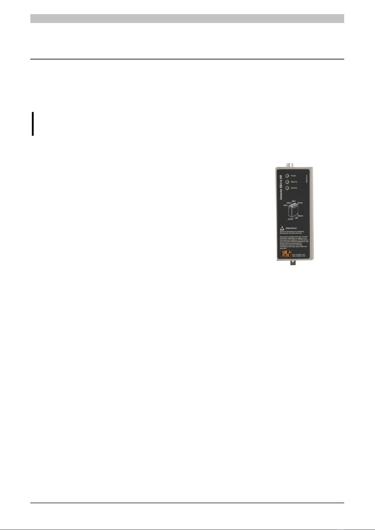
3.2 SDL4/DVI Converter for Automation PCs...................................................................................................... 8
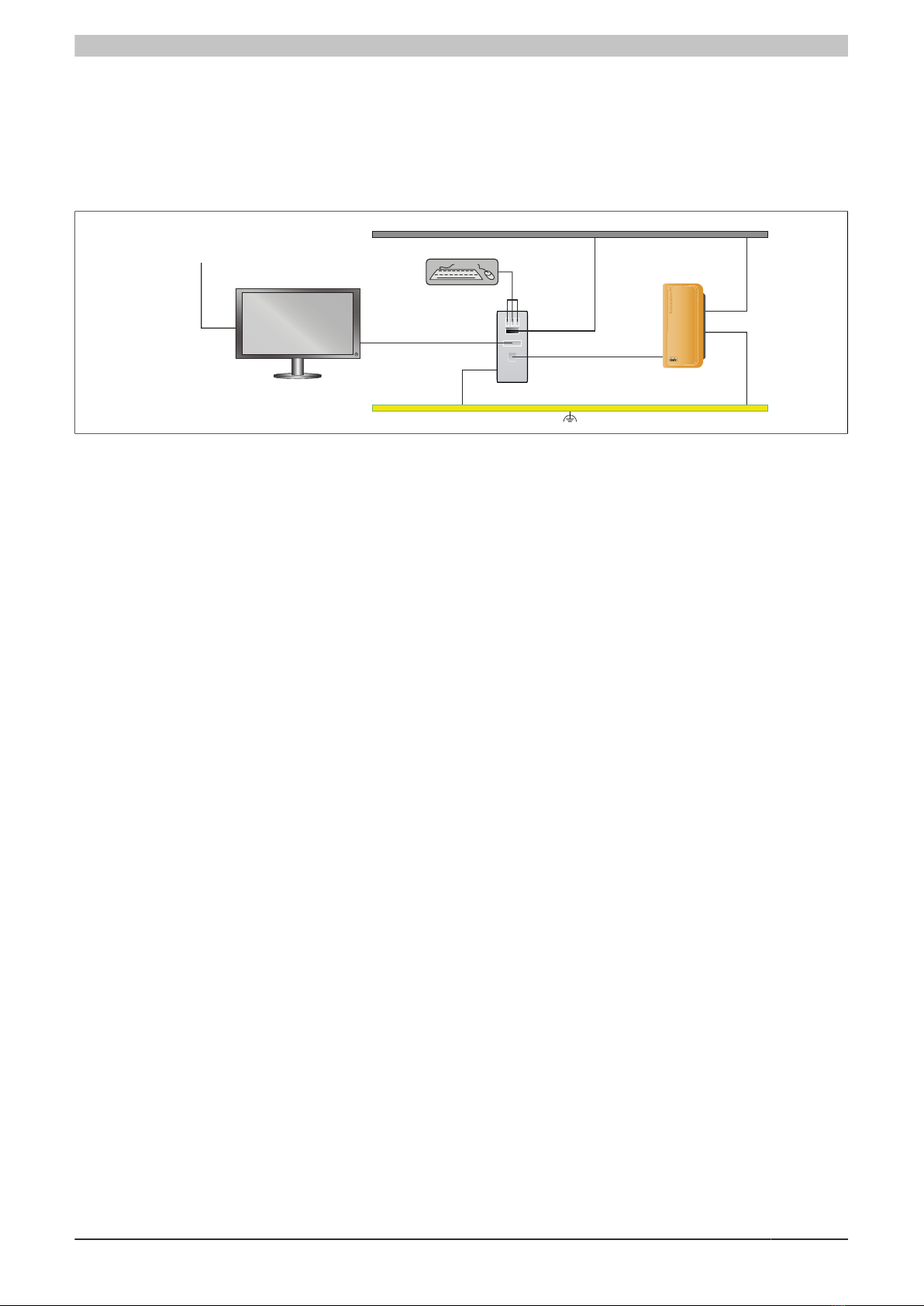
3.3 Connection options......................................................................................................................................... 9
3.3.1 SDL4-DVI connection option..................................................................................................................... 9
3.3.2 General limitations/characteristics........................................................................................................... 10
3.3.2.1 USB endpoint analysis.......................................................................................................................10
3.4 Design/Configuration.....................................................................................................................................11
3.5 System data.................................................................................................................................................. 12
3.5.1 5COSD4.1002-00.................................................................................................................................... 12
3.5.1.1 General information............................................................................................................................12
3.5.1.2 Order data..........................................................................................................................................12
3.5.1.3 Technical data....................................................................................................................................13
3.5.1.4 Dimensions.........................................................................................................................................14
3.5.2 Device interfaces and slots..................................................................................................................... 15
3.5.2.1 Device interfaces - Overview.............................................................................................................15
3.6 Overview........................................................................................................................................................19
4 Dimensioning...........................................................................................................20
4.1 Spacing for air circulation............................................................................................................................. 20
5 Installation and wiring............................................................................................ 21
5.1 Basic information...........................................................................................................................................21
5.2 Installing the SDL4/DVI Converter................................................................................................................23
5.2.1 Procedure................................................................................................................................................ 23
5.3 Installing the cable strain relief clip.............................................................................................................. 24
5.4 Connecting to the power grid....................................................................................................................... 25
5.4.1 Installing the DC power cable................................................................................................................. 25
5.4.1.1 Wiring................................................................................................................................................. 25
5.4.2 Connecting the power supply to a B&R device...................................................................................... 25
5.4.3 Grounding concept.................................................................................................................................. 27
5.5 Connecting cables.........................................................................................................................................28
5.6 Removing the SDL4/DVI Converter..............................................................................................................29
5.6.1 Procedure................................................................................................................................................ 29

Table of contents
SDL4/DVI Converter User's manual V1.12 3
6 Commissioning........................................................................................................30
6.1 Basic information...........................................................................................................................................30
6.2 Switching on the device for the first time..................................................................................................... 30
6.2.1 General information before switching on the device...............................................................................30
6.2.2 Switching on the SDL4/DVI Converter....................................................................................................30
7 Software................................................................................................................... 31
7.1 Updates......................................................................................................................................................... 31
8 Maintenance.............................................................................................................32
8.1 Repairs/Complaints and replacement parts..................................................................................................32
9 International and national certifications...............................................................33
9.1 Directives and declarations...........................................................................................................................33
9.1.1 CE marking..............................................................................................................................................33
9.1.2 EMC Directive..........................................................................................................................................33
9.2 Certifications..................................................................................................................................................34
9.2.1 UL certification.........................................................................................................................................34
9.2.2 EAC..........................................................................................................................................................34
10 Accessories........................................................................................................... 35
10.1 General accessories................................................................................................................................... 35
10.1.1 Accessories - Order data...................................................................................................................... 35
10.2 0TB103.9x................................................................................................................................................... 36
10.2.1 General information............................................................................................................................... 36
10.2.2 Order data............................................................................................................................................. 36
10.2.3 Technical data....................................................................................................................................... 36
10.3 Cables......................................................................................................................................................... 37
10.3.1 SDL3/SDL4 cables................................................................................................................................ 37
10.3.1.1 5CASD3.xxxx-00.............................................................................................................................. 37
10.3.2 DVI cables............................................................................................................................................. 40
10.3.2.1 5CADVI.0xxx-00...............................................................................................................................40
10.4 Cable strain relief clip................................................................................................................................. 43
10.4.1 5ACCRHMI.0012-000............................................................................................................................ 43
10.4.1.1 General information..........................................................................................................................43
10.4.1.2 Order data........................................................................................................................................43
10.4.1.3 Technical data..................................................................................................................................43
11 Environmentally friendly disposal.......................................................................44
11.1 Separation of materials............................................................................................................................... 44

Introduction
4 SDL4/DVI Converter User's manual V1.12
1 Introduction
1.1 Manual history
Version Date Change
1.00 June 2019 •First version
1.05 July 2019 •Updated "+24 VDC power supply" on page 15.
1.10 September 2019 •Updated temperature specifications in "Technical data" on page 13 and "USB interfaces" on page
18.
1.11 January 2020 •Updated temperature specifications in "Technical data" on page 13 and "USB interfaces" on page
18; updated weight specifications.
1.12 April 2020 •Updated temperature specifications in "Technical data" on page 13 and "USB interfaces" on page
18.
1.2 Information about this document
This document is not intended for end customers! The safety guidelines required for end customers
must be incorporated into the operating instructions for end customers in the respective national lan-
guage by the machine manufacturer or system provider.
1.2.1 Organization of notices
Safety notices
Contain only information that warns of dangerous functions or situations.
Signal word Description
Danger! Failure to observe these safety guidelines and notices will result in death, severe injury or substantial damage to property.
Warning! Failure to observe these safety guidelines and notices can result in death, severe injury or substantial damage to property.
Caution! Failure to observe these safety guidelines and notices can result in minor injury or damage to property.
Notice! Failure to observe these safety guidelines and notices can result in damage to property.
General notices
Contain useful information for users and instructions for avoiding malfunctions.
Signal word Description
Information: Useful information, application tips and instructions for avoiding malfunctions.
1.2.2 Guidelines
European dimension standards apply to all dimension diagrams.
All dimensions in mm.
Unless otherwise specified, the following general tolerances apply:
Nominal dimension range General tolerance per
DIN ISO 2768 medium
Up to 6 mm ±0.1 mm
Over 6 to 30 mm ±0.2 mm
Over 30 to 120 mm ±0.3 mm
Over 120 to 400 mm ±0.5 mm
Over 400 to 1000 mm ±0.8 mm

General safety guidelines
SDL4/DVI Converter User's manual V1.12 5
2 General safety guidelines
2.1 Intended use
Programmable logic controllers, operating and monitoring devices (e.g. industrial PCs, Power Panels, Mobile Pan-
els) as well as uninterruptible power supplies from B&R have been designed, developed and manufactured for
normal use in industry. They have not been designed, developed and manufactured for use that involves fatal
risks or hazards that could result in death, injury, serious physical harm or other loss without the assurance of
exceptionally stringent safety precautions. In particular, this includes the use of these systems to monitor nuclear
reactions in nuclear power plants, flight control systems, air traffic control, the control of mass transport vehicles,
medical life support systems and the control of weapon systems.
2.2 Protection against electrostatic discharge
Electrical assemblies that can be damaged by electrostatic discharge (ESD) must be handled accordingly.
2.2.1 Packaging
•Electrical assemblies with housing:
Do not require special ESD packaging but must be handled properly (see "Electrical assemblies with hous-
ing").
•Electrical assemblies without housing:
Are protected by ESD-suitable packaging.
2.2.2 Regulations for proper ESD handling
Electrical assemblies with housing
•Do not touch the connector contacts of connected cables.
•Do not touch the contact tips on circuit boards.
Electrical assemblies without housing
The following applies in addition to "Electrical assemblies with housing":
•All persons handling electrical assemblies and devices in which electrical assemblies are installed must
be grounded.
•Assemblies are only permitted to be touched on the narrow sides or front plate.
•Always place assemblies on suitable surfaces (ESD packaging, conductive foam, etc.). Metallic surfaces
are not suitable surfaces!
•Assemblies must not be subjected to electrostatic discharges (e.g. due to charged plastics).
•A minimum distance of 10 cm from monitors or television sets must be maintained.
•Measuring instruments and devices must be grounded.
•Test probes of floating potential measuring instruments must be discharged briefly on suitable grounded
surfaces before measurement.
Individual components
•ESD protective measures for individual components are implemented throughout B&R (conductive floors,
shoes, wrist straps, etc.).
•The increased ESD protective measures for individual components are not required for handling B&R
products at customer locations.
2.3 Regulations and measures
Electronic devices are generally not failsafe. If the programmable logic controller, operating or control device or
uninterruptible power supply fails, the user is responsible for ensuring that connected devices (such as motors)
are brought to a safe state.

General safety guidelines
6 SDL4/DVI Converter User's manual V1.12
When using programmable logic controllers as well as when using operating and monitoring devices as control
systems in conjunction with a Soft PLC (e.g. B&R Automation Runtime or similar product) or Slot PLC (e.g. B&R
LS251 or similar product), the safety measures that apply to industrial controllers (protection by protective equip-
ment such as emergency stops) must be observed in accordance with applicable national and international regu-
lations. This also applies to all other connected devices, such as drives.
All work such as installation, commissioning and servicing are only permitted to be carried out by qualified person-
nel. Qualified personnel are persons who are familiar with the transport, installation, assembly, commissioning and
operation of the product and have the appropriate qualifications for their job (e.g. IEC 60364). National accident
prevention regulations must be observed.
The safety guidelines, information about connection conditions (nameplate and documentation) and limit values
specified in the technical data must be read carefully before installation and commissioning and must be strictly
observed.
2.4 Transport and storage
During transport and storage, devices must be protected against undue stress (mechanical stress, temperature,
humidity, aggressive atmosphere).
2.5 Installation
•The devices are not ready for use and must be installed and wired according to the requirements of this
documentation in order to comply with EMC limit values.
•Installation must be carried out according to the documentation using suitable equipment and tools.
•Devices are only permitted to be installed by qualified personnel when the power is switched off. The control
cabinet must first be disconnected from the power supply and secured against being switched on again.
•General safety regulations and national accident prevention regulations must be observed.
•The electrical installation must be carried out in accordance with relevant regulations (e.g. wire cross sec-
tion, fuse protection, protective ground connection).
2.6 Operation
2.6.1 Protection against contact with electrical parts
In order to operate programmable logic controllers, operating and monitoring devices and uninterruptible power
supplies, it is necessary for certain components to carry dangerous voltages over 42 VDC. Touching one of these
components can result in a life-threatening electric shock. There is a risk of death, serious injury or damage to
property.
Before switching on programmable logic controllers, operating and monitoring devices and uninterruptible power
supplies, it must be ensured that the housing is properly connected to ground potential (PE rail). The ground
connection must also be made if the operating and monitoring device and uninterruptible power supply are only
connected for testing purposes or only operated for a short time!
Before switching on, live parts must be securely covered. All covers must be kept closed during operation.
2.6.2 Ambient conditions - Dust, moisture, aggressive gases
The use of operating and monitoring devices (e.g. industrial PCs, Power Panels, Mobile Panels) and uninterruptible
power supplies in dusty environments must be avoided. This can otherwise result in dust deposits that affect the
functionality of the device, especially in systems with active cooling (fans), which may no longer ensure sufficient
cooling.
The presence of aggressive gases in the environment can also result in malfunctions. In combination with high
temperature and relative humidity, aggressive gases – for example with sulfur, nitrogen and chlorine components
– trigger chemical processes that can very quickly impair or damage electronic components. Blackened copper
surfaces and cable ends in existing installations are indicators of aggressive gases.
When operated in rooms with dust and condensation that can endanger functionality, operating and monitoring
devices such as Automation Panels or Power Panels are protected on the front against the ingress of dust and
moisture when installed correctly (e.g. cutout installation). The back of all devices must be protected against the
ingress of dust and moisture, however, or the dust deposits must be removed at suitable intervals.

General safety guidelines
SDL4/DVI Converter User's manual V1.12 7
2.6.3 Programs, viruses and malicious programs
Any data exchange or installation of software using data storage media (e.g. floppy disk, CD-ROM, USB flash
drive) or via networks or the Internet poses a potential threat to the system. It is the direct responsibility of the user
to avert these dangers and to take appropriate measures such as virus protection programs and firewalls to protect
against them and to use only software from trustworthy sources.
2.7 Cybersecurity disclaimer for products
B&R products communicate via a network interface and were developed for secure connection with internal and,
if necessary, other networks such as the Internet.
Information:
In the following, B&R products are referred to as "product" and all types of networks (e.g. internal
networks and the Internet) are referred to as "network".
It is the sole responsibility of the customer to establish and continuously ensure a secure connection between
the product and the network. In addition, appropriate security measures must be implemented and maintained
to protect the product and entire network from any security breaches, unauthorized access, interference, digital
intrusion, data leakage and/or theft of data or information.
B&R Industrial Automation GmbH and its subsidiaries are not liable for damages and/or losses in connection
with security breaches, unauthorized access, malfunctions, digital intrusion, data leakage and/or theft of data or
information.
The aforementioned appropriate security measures include, for example:
•Segmentation of the network (e.g. separation of the IT network from the control network1))
•Use of firewalls
•Use of authentication mechanisms
•Encryption of data
•Use of anti-malware software
Before B&R releases products or updates, they are subjected to appropriate functional testing. Independently of
this, we recommend that our customers develop their own test processes in order to be able to check the effects
of changes in advance. Such changes include, for example:
•Installation of product updates
•Significant system modifications such as configuration changes
•Deployment of updates or patches for third-party software (non-B&R software)
•Hardware replacement
These tests should ensure that implemented security measures remain effective and that systems in the customer's
environment behave as expected.
1) The term "control network" refers to computer networks used to connect control systems. The control network can be divided into zones, and there can be
several separate control networks within a company or site. The term "control systems" refers to all types of B&R products such as controllers (e.g. X20), HMI
systems (e.g. Power Panel T30), process control systems (e.g. APROL) and supporting systems such as engineering workstations with Automation Studio.

System overview
8 SDL4/DVI Converter User's manual V1.12
3 System overview
3.1 Information about this user's manual
This user's manual contains all necessary information about the SDL4/DVI Converter.
For information about B&R industrial PCs, see the respective user's manuals.
Information:
All specifications in dimension diagrams and associated tables are in millimeters [mm].
3.2 SDL4/DVI Converter for Automation PCs
The SDL4/DVI Converter makes operation via SDL4 with Automation PCs
possible for monitors and panels that are only equipped with a DVI inter-
face. This makes it easy to upgrade systems to SDL4 as part of retrofit
measures and conversions.

System overview
SDL4/DVI Converter User's manual V1.12 9
3.3 Connection options
3.3.1 SDL4-DVI connection option
With the SDL4/DVI Converter, monitors and panels that are only equipped with a DVI interface can also be con-
nected to a B&R industrial PC with SDL4 even over long distances.
Various USB devices can be connected to the 3 available USB interfaces (e.g. keyboard, mouse).
Monitor/Panel
B&R industrial PC
USB devices
DVI-D cable
SDL3/SDL4 cables
SDL4/DVI Converter
Power supply (SELV/PELV)
Power supply
Maximum cable length for SDL4: 100 m
Maximum cable length for DVI and USB: 5 m
Necessary components:
•Monitor or panel with DVI interface
•B&R industrial PC with SDL4 interface
•SDL4/DVI Converter
•DVI-D cable, SDL3/SDL4 cable
Optional components:
°USB devices and USB cables
Limitations
•Service and diagnostic data is not transferred.
•Data transfer is limited to the DVI specification (single link). If SDL panels are connected, they can only
be used as DVI display units.

System overview
10 SDL4/DVI Converter User's manual V1.12
3.3.2 General limitations/characteristics
•USB 2.0 transfer is limited to 150 Mbit/s with SDL4.
•If multiple USB devices are connected to the panel, it is important to note that only a certain number of
USB endpoints are available. If this number is exceeded, communication problems with the USB devices
may occur. This property is explained in detail below.
3.3.2.1 USB endpoint analysis
It is possible to analyze the number and type of endpoints on a particular USB device. Third-party USB analysis
tools can be used for this purpose.
The SDL4 connection has a limited number of USB IN and USB OUT endpoints. This can cause problems if multiple
USB devices are connected at the same time.
Endpoints
Devices must be distinguished from endpoints:
A device can be considered a USB peripheral that connects to a host, such as a mouse, keyboard, camera, flash
drive or mass storage device such as a hard disk.
Endpoints can be considered as data sources or storage locations, i.e. buffers that cache data during a transaction.
This means that a USB device can have multiple endpoints. There is no direct relation between the number of
endpoints and the number of devices supported by a USB port.
Devices
SDL4 technology currently supports up to seven USB devices. Hubs are not counted since they are transparent
(not visible) from the user's perspective. They are not considered as a device, nor are they counted in relation
to endpoints.
The limitation concerning the maximum number of connected devices or maximum number of endpoints applies
as soon as one of the maximum values is reached. For example, if all endpoints are assigned (i.e. allocated) by
connecting two devices, no more devices are permitted to be connected (although the maximum of seven devices
has not yet been reached).
Hubs
SDL4 currently supports up to eight downstream ports per hub. This means that it is possible to identify all eight
ports on a given hub. By comparison, if SDL4 supported only four ports per hub, ports five to eight – on an eight-
port hub – would be switched off and therefore unusable.
If more than one hub is connected (e.g. if several hubs are linked together), the limit of eight ports per hub remains.
Determining the maximum available endpoints
A certain number of endpoints is available depending on the transfer rate of the devices used.
Endpoints
Transfer rate of the devices IN OUT
High speed 11 12
Full speed / Low speed 12 12

System overview
SDL4/DVI Converter User's manual V1.12 11
3.4 Design/Configuration
Configuration
SDL4/DVI Converter Select 1
5COSD4.1002-00 (SDL4/DVI)
SDL3/SDL4/PoE cables Select 1
5CASD3.0030-00 5CASD3.0050-00 5CASD3.0100-00 5CASD3.0150-00
5CASD3.0200-00 5CASD3.0300-00 5CASD3.0500-00 5CASD3.1000-00
DVI cables Select 1
5CADVI.0018-00 5CADVI.0050-00
Terminal blocks Select 1
Power supply connector
0TB103.9 0TB103.91
Accessories Optional selection
Cable strain relief clip
5ACCRHMI.0012-000

System overview
12 SDL4/DVI Converter User's manual V1.12
3.5 System data
3.5.1 5COSD4.1002-00
3.5.1.1 General information
The SDL4/DVI Converter makes operation via SDL4 with Automation PCs possible for monitors and panels that
are only equipped with a DVI interface. This makes it easy to upgrade systems to SDL4 as part of retrofit measures
and conversions.
3.5.1.2 Order data
Model number Short description Figure
Converter
5COSD4.1002-00 SDL4/DVI Converter
Required accessories
Accessories
0TB103.9 Connector 24 VDC - 3-pin, female - Screw clamp terminal block
3.31 mm²
0TB103.91 Connector 24 VDC - 3-pin, female - Cage clamp terminal block
3.31 mm²
SDL3/SDL4/PoE cables
5CASD3.0030-00 SDL3/SDL4/FT50 cable - 3 m - FT50 including Power over Eth-
ernet
5CASD3.0050-00 SDL3/SDL4/FT50 cable - 5 m - FT50 including Power over Eth-
ernet
5CASD3.0100-00 SDL3/SDL4/FT50 cable - 10 m - FT50 including Power over Eth-
ernet
5CASD3.0150-00 SDL3/SDL4/FT50 cable - 15 m - FT50 including Power over Eth-
ernet
5CASD3.0200-00 SDL3/SDL4/FT50 cable - 20 m - FT50 including Power over Eth-
ernet
5CASD3.0300-00 SDL3/SDL4/FT50 cable - 30 m - FT50 including Power over Eth-
ernet
5CASD3.0500-00 SDL3/SDL4/FT50 cable - 50 m - FT50 including Power over Eth-
ernet
5CASD3.1000-00 SDL3/SDL4 cable - 100 m
Optional accessories
Accessories
5ACCRHMI.0000-000 REP HMI grounding clip
5ACCRHMI.0012-000 REP strain relief USB - For SDL4/DVI Converter
DVI cables
5CADVI.0018-00 DVI-D cable - 1.8 m
5CADVI.0050-00 DVI-D cable - 5 m
Table 1: 5COSD4.1002-00 - Order data

System overview
SDL4/DVI Converter User's manual V1.12 13
3.5.1.3 Technical data
Information:
The following specified characteristic data, features and limit values are only valid for these individual
components and may differ from those of the complete system. The data specified for the complete
system applies to the complete system in which this individual component is used, for example.
Model number 5COSD4.1002-00
General information
LEDs Power, SDL4 In, DVI Out
B&R ID code 0xF4EA
Certifications
CE Yes
UL cULus E115267
Industrial control equipment
Interfaces
USB
Quantity 3
Type USB 2.0
Variant Type A
Transfer rate Low speed (1.5 Mbit/s), full speed (12 Mbit/s) to high speed (480 Mbit/s)
DVI interface
Quantity 1
Variant DVI-I
Type DVI-D (single link)
SDL4 In
Quantity 1
Variant Female RJ45 connector, shielded
Type SDL4
Electrical properties
Nominal voltage 24 VDC ±25%, SELV 1)
Nominal current Max. 0.5 A
Overvoltage category per EN 61131-2 II
Galvanic isolation Yes
Operating conditions
Pollution degree per EN 61131-2 Pollution degree 2
Degree of protection per EN 60529 IP20
Ambient conditions
Temperature
Operation 0 to 55°C 2)3)
Storage -20 to 60°C
Transport -20 to 60°C
Relative humidity
Operation 5 to 90%, non-condensing
Storage 5 to 95%, non-condensing
Transport 5 to 95%, non-condensing
Vibration 4)
Operation (continuous) 2 to 9 Hz: 1.75 mm amplitude / 9 to 200 Hz: 0.5 g peak
Operation (occasional) 2 to 9 Hz: 3.5 mm amplitude / 9 to 200 Hz: 1 g peak
Storage 2 to 8 Hz: 7.5 mm amplitude / 8 to 200 Hz: 2 g peak / 200 to 500 Hz: 4 g peak
Transport 2 to 8 Hz: 7.5 mm amplitude / 8 to 200 Hz: 2 g peak / 200 to 500 Hz: 4 g peak
Shock 4)
Operation 15 g peak, 11 ms
Storage 30 g peak, 6 ms
Transport 30 g peak, 6 ms
Elevation
Operation Max. 3000 m 2)
Mechanical properties
Housing
Material Aluminum
Coating White
Dimensions
Width 40 mm
Height 100 mm
Depth 80 mm
Weight Approx. 420 g
Table 2: 5COSD4.1002-00 - Technical data
1) EN 60950 requirements must be observed.
2) The temperature specifications correspond to a specification at 500 meters. The max. ambient temperature is typically derated 1°C per 1000 meters starting
at 500 m above sea level.
3) Depends on the total power of the connected USB devices, see section "USB interfaces".
4) Top-hat rail clamp set X20AC0RF1 can also be used for improved installation / vibration resistance.
Vibration testing is performed per EN 60068-2-6. Shock testing is performed per EN 60068-2-27.

System overview
SDL4/DVI Converter User's manual V1.12 15
3.5.2 Device interfaces and slots
3.5.2.1 Device interfaces - Overview
Information:
The interfaces available on the device or module are numbered for the purpose of clear differentiation.
The numbering used by the operating system may deviate, however.
View A
View B A B
Legend
1"LED status indicators" on page 18 4"+24 VDC power supply" on page 15
2"DVI Out interface" on page 17 5"Grounding" on page 16
3"USB interfaces" on page 18 6"SDL4 In interface" on page 16
3.5.2.1.1 +24 VDC power supply
Danger!
The device is only permitted to be supplied with a SELV/PELV power supply or with safety extra-low
voltage (SELV) per EN 60950.
The necessary 3-pin connector is not included in delivery; for suitable accessories, see "0TB103.9x" on page 36.
The device is protected against overload and reverse polarity by a soldered fuse (10 A, fast-acting). If the fuse
is defective (e.g. due to overload), the device must be sent to B&R for repairs. If the polarity is reversed, it is not
necessary to replace the fuse.
Pin Description Figure
1 +
2 Functional ground
3 -
•Reverse polarity protection
•3-pin
•Male
Electrical properties
Nominal voltage 24 VDC ±25%, SELV1)
Nominal current Max. 0.5 A
Overvoltage category per EN 61131-2 II
Galvanic isolation Yes
1) EN 60950 requirements must be observed.

System overview
16 SDL4/DVI Converter User's manual V1.12
3.5.2.1.2 Grounding
Caution!
The functional ground (power supply pin 2 and ground connection) must be connected to the central
grounding point (e.g. control cabinet or system) via the shortest possible path with the lowest possible
resistance and with the largest possible wire cross section. This type of grounding is mandatory for
proper functionality.
For example, a copper strip must be attached to the ground connection
at a central grounding point of the control cabinet or system in which the
device is installed. The wire cross section should be as large as possible
(at least 2.5 mm²).
3.5.2.1.3 SDL4 In interface
The SDL4 In interface is a female RJ45 connector and operated with SDL4
transmission technology.
Information:
Hot plugging output devices on the interface for service purposes is supported by the hardware and
graphic drivers of approved operating systems.
A maximum of 500 mating cycles are specified for this interface.

System overview
SDL4/DVI Converter User's manual V1.12 17
3.5.2.1.4 DVI Out interface
The DVI interface is a female DVI-I connector with a
maximum resolution of 1920 x 1200 pixels and uses
DVI-D transmission technology.
Information:
Hot plugging output devices on the interface for service purposes is supported by the hardware and
graphic drivers of approved operating systems.
A maximum of 100 mating cycles are specified for this interface.
Pinout
Pin Pinout Description Pin Pinout Description
1 TMDS data 2- DVI lane 2 (negative) 16 HPD Hot plug detection
2 TMDS data 2+ DVI lane 2 (positive) 17 TMDS data 0- DVI lane 0 (negative)
3 TMDS data 2/4 SHIELD Shield for data pairs 2 and 4 18 TMDS data 0+ DVI lane 0 (positive)
4Not connected Not connected 19 TMDS data 0/XUSB1
SHIELD Shield of data pair 0 and USB1
5 Not connected Not connected 20 Not connected Not connected
6 DDC clock DDC-based control signal (clock) 21 Not connected Not connected
7 DDC data DDC-based control signal (data) 22 TMDS clock shield Shield of clock pair
8 Not connected Not connected 23 TMDS clock+ DVI clock (positive)
9 TMDS data 1- DVI lane 1 (negative) 24 TMDS clock - DVI clock (negative)
10 TMDS data 1+ DVI lane 1 (positive) C1 Not connected Not connected
11 TMDS data 1/XUSB0
SHIELD Shield of data pair 1 and USB0 C2 Not connected Not connected
12 Not connected Not connected C3 Not connected Not connected
13 Not connected Not connected C4 Not connected Not connected
14 +5 V power1) +5 V power supply C5 Not connected Not connected
15 Ground (return for +5 V,
HSync and VSync) Ground - -
1) Protected internally by a multifuse.
3.5.2.1.4.1 Cable lengths and resolutions for DVI transfer
The following table shows the relationship between segment length and maximum resolution depending on the
DVI cable:
ResolutionDVI cable
Segment length [m]
VGA
640 x 480
SVGA
800 x 600
XGA
1024 x 768
HD
1366 x 768
SXGA
1280 x 1024
UXGA
1600 x 1200
FHD
1920 x 1080
1.8 5CADVI.0018-00 5CADVI.0018-00 5CADVI.0018-00 5CADVI.0018-00 5CADVI.0018-00 5CADVI.0018-00 5CADVI.0018-00
55CADVI.0050-00 5CADVI.0050-00 5CADVI.0050-00 5CADVI.0050-00 5CADVI.0050-00 5CADVI.0050-00 5CADVI.0050-00

System overview
18 SDL4/DVI Converter User's manual V1.12
3.5.2.1.5 LED status indicators
Position LED Color Status Explanation
Power
1)
Green On Device ready for operation
On Active SDL4 connection.SDL4 In
2)
Yellow
Off No active SDL4 connection.
Blinking
(approx. 2.5 Hz)
Active DVI connection.DVI Out
3)
Yellow
Off No DVI connection.
3.5.2.1.6 USB interfaces
Warning!
USB peripheral devices can be connected to the USB interfaces. Due to the variety of USB devices
available on the market, B&R cannot guarantee their functionality. The functionality of USB devices
available from B&R is guaranteed.
USB1-3
Standard USB 2.0
Variant Type A, female
Quantity 3
Low speed (1.5 Mbit/s)
Full speed (12 Mbit/s)
Transfer rate
High speed (480 Mbit/s)
Current-carrying capacity1)
USB1-3 Max. 0.5 A per USB
Max. ambient temperature (complete system) Rev. B0 Rev. C0 Rev. D0
At 3.25 W USB total power 40°C 50°C 55°C
At 7.50 W USB total power 35°C 40°C 50°C
Cable length Max. 5 m (without hub)
1) The USB interfaces are protected by a maintenance-free "USB current-limiting switch" (max. 0.5 A).

System overview
SDL4/DVI Converter User's manual V1.12 19
3.6 Overview
Model number Short description Page
Accessories
0TB103.9 Connector 24 VDC - 3-pin female - Screw clamp terminal block 3.31 mm² 36
0TB103.91 Connector 24 VDC - 3-pin female - Cage clamp terminal block 3.31 mm² 36
5ACCRHMI.0012-000 REP strain relief USB - For SDL4/DVI Converter 43
Converter
5COSD4.1002-00 SDL4/DVI Converter 12
DVI cables
5CADVI.0018-00 DVI-D cable - 1.8 m 40
5CADVI.0050-00 DVI-D cable - 5 m 40
SDL3/SDL4/PoE cables
5CASD3.0030-00 SDL3/SDL4/FT50 cable - 3 m - FT50 including Power over Ethernet 37
5CASD3.0050-00 SDL3/SDL4/FT50 cable - 5 m - FT50 including Power over Ethernet 37
5CASD3.0100-00 SDL3/SDL4/FT50 cable - 10 m - FT50 including Power over Ethernet 37
5CASD3.0150-00 SDL3/SDL4/FT50 cable - 15 m - FT50 including Power over Ethernet 37
5CASD3.0200-00 SDL3/SDL4/FT50 cable - 20 m - FT50 including Power over Ethernet 37
5CASD3.0300-00 SDL3/SDL4/FT50 cable - 30 m - FT50 including Power over Ethernet 37
5CASD3.0500-00 SDL3/SDL4/FT50 cable - 50 m - FT50 including Power over Ethernet 37
5CASD3.1000-00 SDL3/SDL4/FT50 cable - 100 m - FT50 including Power over Ethernet 37

Dimensioning
20 SDL4/DVI Converter User's manual V1.12
4 Dimensioning
4.1 Spacing for air circulation
To ensure sufficient air circulation, a specified clearance must be provided above, below, to the side and behind
the device. For the minimum specified clearance, see the following diagrams. This is valid for all variants.
Information:
The following figure and table exclusively show the thermal view of the complete system. If additional
space is required for operating or servicing the device or using accessories (e.g. cable strain relief
clips), this must be taken into account during installation.
Legend
1) Air outlet 2) Air inlet
Spacing
Description Dimension Description Dimension
S1 ≥ 100 S2 ≥ 50
S3 ≥ 100 S4 ≥ 50
Caution!
The specified spacing for air circulation is based on worst-case operation at the maximum specified
ambient temperature. The maximum specified ambient temperature is not permitted to be exceeded!
Table of contents
Other B&R Media Converter manuals
Popular Media Converter manuals by other brands

StarTech.com
StarTech.com ST122HD202 quick start guide

Albalá Ingenieros
Albalá Ingenieros HVM0002C01 manual

PS Audio
PS Audio PerfectWave DirectStream Owner's reference

ADF Web
ADF Web HD67508-A1-232 user manual

König Electronic
König Electronic KN-AVSPLIT10 manual

Okto Research
Okto Research dac8 Stereo owner's manual