manuals.online logo
Brands
  1. Home
  2. •
  3. Brands
  4. •
  5. Bang & Olufsen
  6. •
  7. Turntable
  8. •
  9. Bang & Olufsen BEOGRAM 4002 User manual

Bang & Olufsen BEOGRAM 4002 User manual

Other manuals for BEOGRAM 4002

2

This manual suits for next models

1

Other Bang & Olufsen Turntable manuals

Bang & Olufsen Beogram 3000 User manual

Bang & Olufsen

Bang & Olufsen Beogram 3000 User manual

Bang & Olufsen Beogram 3000 5901 User manual

Bang & Olufsen

Bang & Olufsen Beogram 3000 5901 User manual

Bang & Olufsen Beogram 6500 User manual

Bang & Olufsen

Bang & Olufsen Beogram 6500 User manual

Bang & Olufsen BEOGRAM 4002 User manual

Bang & Olufsen

Bang & Olufsen BEOGRAM 4002 User manual

Bang & Olufsen beogram 2400 User manual

Bang & Olufsen

Bang & Olufsen beogram 2400 User manual

Bang & Olufsen Beogram 5500 User manual

Bang & Olufsen

Bang & Olufsen Beogram 5500 User manual

Bang & Olufsen Beogram 3300 User manual

Bang & Olufsen

Bang & Olufsen Beogram 3300 User manual

Bang & Olufsen BEOCENTER 3600 User manual

Bang & Olufsen

Bang & Olufsen BEOCENTER 3600 User manual

Bang & Olufsen Beogram 4000c User manual

Bang & Olufsen

Bang & Olufsen Beogram 4000c User manual

Bang & Olufsen Beogram 3000 User manual

Bang & Olufsen

Bang & Olufsen Beogram 3000 User manual

Bang & Olufsen Beogram 2200 5721 User manual

Bang & Olufsen

Bang & Olufsen Beogram 2200 5721 User manual

Bang & Olufsen beogram 3000 5211 User manual

Bang & Olufsen

Bang & Olufsen beogram 3000 5211 User manual

Bang & Olufsen Beogram 1200 User manual

Bang & Olufsen

Bang & Olufsen Beogram 1200 User manual

Bang & Olufsen Beogram 4000 User manual

Bang & Olufsen

Bang & Olufsen Beogram 4000 User manual

Bang & Olufsen Beogram 1800 User manual

Bang & Olufsen

Bang & Olufsen Beogram 1800 User manual

Bang & Olufsen Beogram 3000 User manual

Bang & Olufsen

Bang & Olufsen Beogram 3000 User manual

Bang & Olufsen Beocenter 1100 User manual

Bang & Olufsen

Bang & Olufsen Beocenter 1100 User manual

Bang & Olufsen Beogram 5500 User manual

Bang & Olufsen

Bang & Olufsen Beogram 5500 User manual

Bang & Olufsen beogram 2200 User manual

Bang & Olufsen

Bang & Olufsen beogram 2200 User manual

Bang & Olufsen BEOGRAM 1202 User manual

Bang & Olufsen

Bang & Olufsen BEOGRAM 1202 User manual

Bang & Olufsen Beogram 9000 User manual

Bang & Olufsen

Bang & Olufsen Beogram 9000 User manual

Bang & Olufsen BEOGRAM 4002 User manual
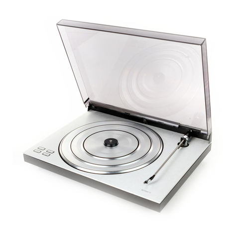
Bang & Olufsen

Bang & Olufsen BEOGRAM 4002 User manual

Bang & Olufsen Beogram RX User manual

Bang & Olufsen

Bang & Olufsen Beogram RX User manual

Popular Turntable manuals by other brands

Technics SP-10 MKIIP Service manual

Technics

Technics SP-10 MKIIP Service manual

Trevi Mpv 1745 SD instructions

Trevi

Trevi Mpv 1745 SD instructions

Noblex NXC1039BT Service manual

Noblex

Noblex NXC1039BT Service manual

I.A.V. Piccolo owner's manual

I.A.V.

I.A.V. Piccolo owner's manual

JVC QL-Y5F Instruction book

JVC

JVC QL-Y5F Instruction book

Gemini CDT-05 MKII product manual

Gemini

Gemini CDT-05 MKII product manual

Rotel RP-820 owner's manual

Rotel

Rotel RP-820 owner's manual

Shuman MC-250BT user manual

Shuman

Shuman MC-250BT user manual

Stanton STR8-150 owner's manual

Stanton

Stanton STR8-150 owner's manual

Audio Technica AT-LPW40WN user manual

Audio Technica

Audio Technica AT-LPW40WN user manual

Crosley McQueen CR7011-GY instruction manual

Crosley

Crosley McQueen CR7011-GY instruction manual

auna TT-Classic Plus instruction manual

auna

auna TT-Classic Plus instruction manual

COMO AUDIO Turntable Analog user manual

COMO AUDIO

COMO AUDIO Turntable Analog user manual

Dual 1009 F owner's manual

Dual

Dual 1009 F owner's manual

AXIOMTEK OPS883-H Series Quick installation guide

AXIOMTEK

AXIOMTEK OPS883-H Series Quick installation guide

Pioneer PL-71 operating instructions

Pioneer

Pioneer PL-71 operating instructions

Vestax PDX-a1 owner's manual

Vestax

Vestax PDX-a1 owner's manual

Denon DP-400 owner's manual

Denon

Denon DP-400 owner's manual

manuals.online logo
manuals.online logoBrands
  • About & Mission
  • Contact us
  • Privacy Policy
  • Terms and Conditions

Copyright 2025 Manuals.Online. All Rights Reserved.

wes
VeeL
ESET
a
a
HS
C471
QR
OL,
B
YPE
5523-5526
EOGRAM
4002-4004
Bang
&
Olutsen
1
O-1
INTRODUCTION
This
service
manual
comprises
Beogram
4002,
type
5513,
which
have
been
constructed
on
the
basis
of
type
5503.
In
the
diagrams
the
components
are
provided
with
an
individual
position
number
and
a
co-ordinate
designation,
e.g.
B3.
This
designation
refers
te
the
placing
on
the
PC
boards
which
are
provided
with
a
printed
division
into
fields
and
with
letters
and
figures
along
the
edge
of
the
PC
board.
Therefore
there
are
no
drawings
of
the
PC
boards
in
the-service
manual.
The
diagram
for
the
CD-4
demodulator
shows
only
one
of
the
stereo
channels
and
the
co-ordinate
designation
for
right
channel
is
bracketed,
e.g.
B3
(C2).
The
diagrams,
which
may
be
unfolded,
are
placed
at
the
back
of
the
manual
so
that
it
is
possible
to
cpen
at
the
preceding
pages
at
the
same
time.
.
The
service
manual
is
complete
and
contains
the
paragraphs
mentioned
in
the
below
table
of
contents.
Supplementary
sheets
will
only
be
made
in
case
of
essential
changes.
CONTENTS
;
SEC.
Technical
data
-
Disassembly
............
ae
eae
e
tana
ene
1
Electrical
description...
2.0.0.0
0002.
c
esc
ec
e
eee
nes
wa
eeees
2
Mechanical
adjustments
-
Lubrication
chart
.
ween
ewer
ace
eters
3
Electrical
adj
justmen?
setae
d
eee
eee
eee
ete
een
eee
4
Fault-finding
...............
See
cece
eer
euseces
Lene
eeaae
wee
8
Mechanical
parts
fist
0.0.0.0...
eeepc
eee
eee
cc
cece
eens
6
Diagram
-
Electrical
parts
list
-
Conditions
of
measurement
.....
T
Service
tips
..
0.
cece
a
cate
ee
eeeeusaceecvnere
8
1-1
Bang
&
Oluisen
BEQGRAM
4002
TECHNICAL
DATA
;
Type
Ne.
$513
Sound
system
Stereo,
matrix
-
a.
Output
2x
0.6m
Speeds
;
33-45
rpm.
Tonearm
Fangential
Autaimatic
racard-size
Yes
Automatic
pickup
movement
Yes
:
Automalic
speed
selection-
Yes
Wow
and
fiutier,
DIN
=
29.05%
—_
Wow
and
flutter,
WRMS.
=<
+0.028%
___
Rumble
DIN
unweighted
>
4508
Rumble
BIN
weighted
=
6508
Speed
deviation
<_
0.02%
Speed
control
range
>
6%
Diat
for
speed
2
pointers
Siyius
pressure
range
Q-+t.d
gram
Tangential
tracking
_
<
.04"
Litt
system
Electronic
Anjishaling
Parallel
tracking,
error
angle
compensaled
Molor
.
Servo
contoted
OG
Drive
system
Bell
Turntable
.
30
cm
1.3
kg
Dust
cover
Hingéd
and
detachable
Fower
supply
.
117
valts
.
Frequency
5G
-
60
Hz
Power
consumption
20
watts
Dimensions
Wx
Hx
DO
49x10
38cm
Weight
it
kg
Pickup
MMC
6000
Styius
Pramanik
diamond
Radius
of
curvature
{GD-4
quadro]
Frequency
range
20-15,000H7
+
1.506
__
20
-
45,000
Hz
(CD-4)
Channel
separation
7000Hz
"
=
25dB
400
-
40.000
Hz
>
20da
"Channel
difference
«
1.508
Infegrmodulation
:
=
1%
Recommended
siyius
pressure
i
gram
_
Compliance
30x
10-Bem/dyn
Eifective
tip
mass
6,22
m9
Output
m¥fomisec,
6.6
mid?
kohms
-
Subject
te
change
without
nctice
DISASSEMBLY
Bang
&
Olufsen
2-1
ELECTRICAL
DESCRIPTION
Since
the
circuitry
of
the
Beogram
4002
-
6000
type
551x
is
basically
idetitical
with
that
of
the
type
550x,
the
electrical
description
will
give
chief
attention
to
those
circuits
which
are
fundamentally
different.
Record
wiping
With
33
activated
in
the
STAND
BY
mode,
the
turntable
will
rotaie
but
the
slide
will
not
travel
in,
making
record
wiping
possible.
In
the
STAND
BY
mode,
1TRI
is
kept
forward
biased
through
LR9,
1R7
and
1R6,
1f33
is
activated,
the
junction
of
1R9
and
LR?
is
connected
to
chassis
potential.
ITR1
is
reverse
biased,
the
collector
goes
high:
this
level
is
transmitted
through
1D8
to
the
base
of
series
transistor
LIC]
as
forward
bias,
with
the
result
that
voltage
is
available
fram
the
power
supply
section.
The
high
level
is
likewise
transmitted
to
the
electronic
switch
through
1D10,
thus
blocking
the
functions
of
the
electronic
switch
and
preventing
slide
transport.
The
turntable
will
rotate
only
as
long
as
33
is
activated.
Tacho
control
The
turntable
is
driven
by
atacho-controlled
DC
motor.
A
generator
in
the
motor
furnishes
an
AC
voltage
whose
frequency
is
dependent
on
the
motor
speed.
This
AC
vollage
is
fed
to
the
network
1CS
-
1R24
to
pin
l
of
LIC3,
The
AC
voltage
is
converted
to
a
square,
which
is
passed
on
to
a
Schmit
trigger.
The
frequency
of
the
square,
dependent
on
the
motor
speed,
controls
one
of
Bang
&
Olufsen
the
output
levels
of
the
Schmitt
trigger;
the
other
output
level
is
controlied
from
a
variable
time
constant
network
consisting
of
1C3
-
1R4-1R16-2R1
for
45r.p.m.
and
103-
}RI5-1R1?
-2R2
for
33
r.p.m.,
Mi
olor
Variabie
frequency
\
i
/
tne
constant
TEI
AA
Qul
schmilt
lngger
LLL.
la
schaitt
trigger
The
output
signal
of
the
Schmitt
trigger
(pin
6)
is
integrated
across
1
R19
-
1C8
and
fed
to
pin
5
which
is
a
differential
amplifier.
The
integrated
signal
at
5
will
be
a
DC
voltage
which
varies
with
the
motor
speed.
This
DC
voltage
is
fed
via
the
differential
amplifier
to
a
power
amplifier.
Fhe
power
amplifier
is
connected
as
a
variable
resistor
to
chassis
potential.
1C10-
1C9-1R20
prayides
negative
feedback
tor
the
power
amplifier
(see
sketch),
preventing
“overregulation™.
1D14
-
1149
-
1R21
provide
a
guarantee
that
the
voltage
across
the
motor
can
only
reach
a
certain
value
(sec
sketch).
Amplit.
cohen
Normal
speed
Speed
mal
When
starting
up
from
motor
stand-still,
the
power
amplifier
will
receive
heavy
drive
to
obtain
very
rapid
speed
increase.
Approx.
§.5¥
is
present
al
the
anode
of
1D
14
so
if
the
voltage
at
pin
4
goes
below
4.6V,
then
1D49,
a
3.3V
Zener
diode,
will
be
forward
biased,
thus
preventing
the
voltage
across
the
motor
from
exceeding
approx.
4.4V
so
that
the
speed
increase
when
starting
up
will
not
be
so
heavy
that
the
motor
reaches
twice
its
wanted
speed,
since
the
motor
regulating
circuil
1s
capable
of
taking
hold
at
twice
that
speed.
The
motor
regulating
circuit
is
powered
with
9V
via
the
series
transistor
LTR2,
controlled
by
1D13.
1D13
is
a
9
Zener
diode.
a
ernad
Bang&Olufsen
|
2-3
Automatic
speed-change
switch,
33
-
45
Motor
contrat
We
will
assume
as
our
starting
point
thai
a
17
cm
record
is
on
the
turntable.
When
ON
is
activated
and
the
slide
begins
travelling
in,
the
conditions
for
lowering
the
pickup
arm
are
not
present.
The
collector
of
1TR6
will
be
low.
This
low
level
is
transmitted
to
the
base
of
ITR8
as
reverse
bias.
The
collector
of
{TR8
and
hence
the
base
of
11C2
will
float,
as
a
result
of
which
11C2
will
be
reverse
biased
and
1RL1
will
be
in
the
neutral
position
(the
33-r.p.m.
positioa).
When
the
slide
passes
the
position
giver
mark
for
touch-down
on
30
cm,
43C1
and
hence
1TR1?
are
reverse
biased,
the
collector
of
1TR17
goes
high,
which
high
level
will
attempt
to
charge
1C2!
of
the
time
constant
network
1R46-
121,
bui
since
the
30
cm
position
marker
is
very
narrow,
1C21]
cannot
obtain
2
full
charge
before
41C1,
and
consequently
1TR17
are
forward
biased.
Since
a4
17
cm
record
is
on
the
turntable,
the
conditions
for.
lowering
the
pickup
arm
are
not
yet
present,
and
the
slide
will
continue
to
travel
in.
The
slide
reaches
the
position
marker
for
25
cm
lower
-
17
cm
speed
change,
41C1
and
hence
1TRI7
are
again
reverse
biased,
this
time
far
a
longer
time
than
for
30
cm
because
the
mark
for
17
cm
speed
change
is
broader
than
the
mark
for
30
cm
lower,
The
high
level
at
1TR17
can
now
have
time
to
charge
1C21,
1IC2
is
forward
biased,
1RL!
operates,
and
the
speed
changes
to
45
r.p.m..
When
the
slide
reaches
the
mark
for
17
cm
lower,
and
we
have
a
17¢m
record
on
the
turntable,
the
conditions
for
lowering
the
pickup
arm
are
present.
The
collector
of
1TR6
goes
high,
which
high
level
is
transmitted
to
the
base
of iT
RS
as
forward
bias.
The
collector
of
1TR8
goes
low,
and
112
is
now
kept
forward
biased
through
1RLI,
1R11,
1R25
and
ITR8.
Lo
pha
Magnet
cail
circuit
Bang
&
Oluisen
The
collector
of
1TR&
is
connected
via
1D32
to
the
"Motor
control
IN”
section
of
the
electronic
switch
so
that
automatic
speed
change
to
43
r.p.m.
can
occur
only
while
the
slide
is
travelling
in
(high
at
the
collector
of
1TR12).
A
low
level
at
the
collector
of
ITR12
places
the
cathode
of
1D32
on
chassis
potential,
and
1C?1
cannot
be
charged.
When
switching
manually
from
33
te
45
r.p.m.,
45
is
activated,
relay
]RL1
operates,
aud
11C2
is
forward
biased
through
IRL1
and
IRiL.
1f33
ts
activated,
the
bias
for
11C2
is
shorted
to
chassis
through
1D12,
LIC2
is
reverse
biased,
and
LRLI
releases.
1D12
prevents
1{C2 from
being
forward
biased
through
19.
IDH
protects
against
induction
peaks.
.
When
the
requirements
for
lowering
the
pickup
have
been
met,
the
collector
o
ITR6
is
high;
this
high
tevel
is
transmitted
via
1D22
to
the
LOWER
section
of
the
electronic
switch
as
a
fixed
level
at
the
cathode
of
1D35,
When
the
slide
switch
passes
the
position
giver
mark,
the
collector
of
1TR17
as
mentioned
before
goes
high;
this
high
level
is
transmitted
to
the
base
of
-
1TR?
as
forward
bias.
1020
will
charge
throngh
1D23,
1TR7
and
1D21.
The
charging
current
in
1C20
gives
a
negative
voltage
jump
at
the
cathode
of
1D22.
This
low
pulse
is
fed
to
the
electronic
switch
to
activate
its
LOWER
.
section.
To
ensure
that.1C20
will
not
pick
up
a
charge
from
the
speed-change
switch
through
1D21
and
1TR7,
1D50
shorts
the
base
of
1TR17
to
chassis
potential
when
the
collector
of
ITR6
is
low.
1219
and
the
time
constant
network
1R4i
-
1C19
ensure
that
automatic
lowering
will
not
occur
when
ihe
detector
arm
reaches
in
above
the
bright
portion
of
the
turntable
(with
ao
record
on
ihe
turntable).
Ifa
low
level
is
applied
to
the
base
of
1TR9,
1TR9
is
reverse
biased,
the
collector
is
high
and
11C4
reverse
biased;
ORLI
will
be
in
the
neutral
position,
+304
If
the
base
of
ITR9
goes
high,
|
TR9
is
forward
biased;
the
collector
goes
low,
and
11C4
is
likewise
forward
biased
and
magnet
coil
ORE
operates.
Parts
of
the
collector
current
of
11C4
will
charge
1C23
across
1R55
and
1R54.
When
1C23
is
charged
to
a
level
of
approx.
0.7V,
1TR10
is
forward
biased.
The
collector
current
in
1TR10
will
impose
a
Joad
on
the
drive
to
ITR9,
1TR9
draws
Jess
current;
this
limits
the
current
in
11C4,
and
hence
the
magnet
coil,
from
4
amps
at
the
memeni
the
magnet
coil
operates
to
approx.
150
mA.
When
1C23
has
accumulated
a
charge,
[R53
and
(R55
are
connected
to
operate
as
base
bias
divider
for
1T
RIO
in
such
a
way
that
the
higher
the
collector
voltage
at
11C4,
the
higher
the
forward
bias
of
ITR10,
1TR10
draws-more
current,
the
base
of
1TR9
is
more
heavily
loaded,
and
the
collector
current
in
11C4
is
limited
as
mentioned
abeve.
1TR10
accordingly
provides
negative
feedback.
Bang
&
Olufsen
|
2-5
DEMODULATOR
Forsicer-
ker
Pick-up
MMC
BOU0
O
PM
equa-|
lizing
eOO\EK
37%
me
latrix
|
Rear
Veastre
sierea
Low
pas
17K
Elektro-
nisk
CD-4
switch
|
Netdel
Eftekt
begrenser
Power
supply
The
CD-4
demodulator
has
a
stabilised
power
supply
of
its
own
which
uses
the
power
supply
of
the
control
circuits
as
reference.
Pa
9
Say
Carrier
detector
The
power
supply
series
transistor,
TR102,
is
forward
biased
by
TR1O1
and
TR1OO,
whose
base
receives
20
V
of
bias.
The
emitter
voltage
of
TR102
is
stabilised
by
TRIO3
and
D101.
30KHz
niveau
input
RH
BkHz
at
PL
Matrix
|
Bang
&
Oluisen
The
carrier
detector
serves
the
purpose
of
limiting
the
lock-in
range
of
the
PLL
if
30
kHz
carrier
drops
out.
Limiting
foHows
the
curve
shown,
the
slope
of
the
curve
(level
range)
being
adjusted
with
R43.
R11
is
used
for
selecting
the
30
kHz
level
at
which
regulation
starts.
JOKHZ
The
matrix
serves
the
purpose
of
mixing
the
sum
and
difference
signals
in
such
a
manner
that
the
front
and
rear
channels
appear
separately.
The
principle
of
the
matrix
is,
in
one
case,
ta
add
the
two
signals
together
to
produce
the
front
signal
and,
in
the
other,
to
subtract
them
so
as
to
obtain
the
rear
signai.
The
difference
signal
is
fed
from
the
output
of
the
ANRS
circuit
ta
the
base
of
TRG.
TR8
and
TR9
operate
as
a
differential
amplifier.
The
two
transisiors
have
a
common
emitter
resistor
so
that,
if
the
current
in
TR
increases,
the
current
in
TR8
will
decrease
conmensurately
and
vice
versa.
..
Since
the
base
of
TR8
is
shorted
to
chassis
potential,
signal-wise,
we
conse-
quenily
obtain
at
the
collector
of
TR9
a
signal
that
is
in
phase
opposition
to
the
signal
at
the
base
of
TR9
and,
at
the
collector
of
TRS,
a
signal
that
is
in
phase
with
the
signal
at
the
base
of
TRY.
The
signals
are
mixed
across
resistors
R81,
R83,
R82
and
R84,
resulting
in
the
appearance
of
the
F
and
R
signais-at
C52
and
C53,
respectively.
,
Bang
&
Oluisen
Stiand
2b
The
silent
circuil
is
tc
ensure
that
the
outputs
of
the
Beogram
6000
are
silent
when
the
pickup
arm
is
not
lowered.
cS2heo
4
CSkyetng
E9,
Electranic
y
CQ-4
suit
When
the
pickup
arm
is
lowered,
approx.
17
V
will
be
present
at
pin
1
of
P8.
The
charge
picked
up
by
C104
ensures
that
the
channels
are
silent
while
the
pickup
arm
is
being
fowered.
When
the
bias
at
the
base
of
TR108
reaches
approx.
+1.2
¥,
TR108
is
forward
biased.
The
collector
of
TR108
goes
low,
TR107
is
reverse
biased,
the
emitter
of
TR107
goes
low,
and
if
a
CD-4
record
is
being
played,
the
low
level
at
the
emitter
of
TR107
will
be
irans-
mitted
to
the
bases
of
TRS,
TR15
and
TR16,
respectively;
both
the
front
and
rear
channels
will
then
be
open.
If
the
pickup
arm
is
raised,
the
voltage
at
pin
1
of
P8
drops
to0
V.
TR108
is
reverse
biased,
the
collector
goes
high
and
TR10?
is
forward
biased.
The
emitter
of
TRi07
goes
high;
this
high
level
is
transmitted
to
the
base
of
TRIS
and,
via
DIOS,
to
the
bases
of
TR16
and
TRS,
TR15,
TRt6
and
TRS
ate
forward
biased
so
that
the
signal
path
in
both
front
and
rear
channels
as
well
as
the
difference
signal
in
the
ANRS
circuit
are
shorted
to
chassis
potential.
7
D106
and
R123
ensure
rapid
discharge
of
C104
when
the
pickup
arm
begins
to
rise.