9
V. Thermal Laminating...
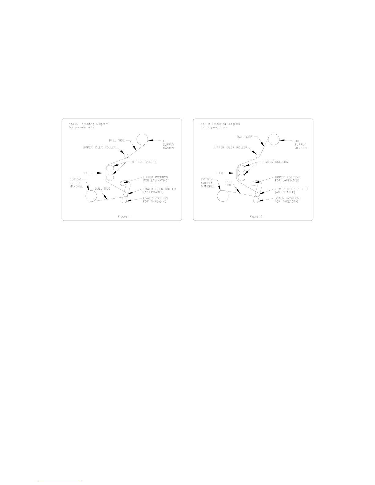
1. Be sure all laminator parts (i.e. safety shield, feed table, etc.) are in their proper positions
and the laminating film is loaded correctly.
2. Set the temperatures according to the film manufacturer’s recommendations for the film
you have chosen. A low-melt film is recommended for inkjet prints. Keep in mind that the
temperature at which you will laminate will vary with different medias and laminating
speeds. See the chart below for approximate temperature ranges. The laminator will take
approximately 25-30 minutes to reach operating temperature. The temperatures will be
indicated on the LCD display.
3 mil DIGIKOTE™ 190°-210°F
5 mil DIGIKOTE™ 220°-230°F
10 mil DIGIKOTE™ 225°-235°F
3. Your new ValueLam 4500 has a digital heat controller. Users can easily adjust the set
temperature to achieve the best quality lamination. The controller has been calibrated to
accurately display the roller temperature in the laminating range.
The heater switch on the right side frame activates the controller. When the switch is turned
on the controller will flash a two letter code and then display the current roller temperature.
When cold, the temperature displayed on the controllers may be different than the actual
ambient temperature to account for correction in the higher temperature range. When the
heater switch is turned on the controller will send power to the heaters, provided the set
temperature is higher than ambient temperature.
When power is being sent to the heaters the controller will illuminate a small red indicator
light in the lower right hand corner of the display. The light goes out when the set
temperature is reached. Power to the heaters cycles on and off when the roller temperature
falls below set temperature during lamination.
4. To determine the set temperature, with the heater switch activated and the current
temperature displayed, press and hold down either the up or down arrow for 3-4 seconds.
The display will change and flash the set temperature and “SU” alternately. After 10
seconds the display will return to the current roller temperature.
To change the set temperature, depress and hold either arrow down for 3-4 seconds until
the set temperature and “SU” flash. Depress and hold the appropriate arrow to raise or
lower the setting. The digits will change slowly initially but will increase speed when held
down longer for large changes. When the desired setting has been reached, depress both
arrows simultaneously to save the Set Temperature.
Each time the machine is turned on it will heat up to the last set temperature. It is advisable
to verify the set temperature when starting to warm up the machine each day.
5. Turn the MOTOR switch ON and perform a test lamination to ensure proper settings for
successful lamination. Watch film as it exits the rollers so it doesn’t wrap around the
rollers. It might be helpful to hold the film at first when starting a lamination run. If any
adjustments are necessary make them now and run another test. Repeat this step until
you obtain desired results.