5
2Mount the System Components
Mounting hardware is not included with the Occupancy Solution Kit. Banner recommends using ¼-20 mounting bolts, self
tapping screws, magnetic mounts, or hardware that is compatible with the mounting surface.
Do not mount any radios inside metal enclosures. Metal around the radios can reduce wireless signal strength.
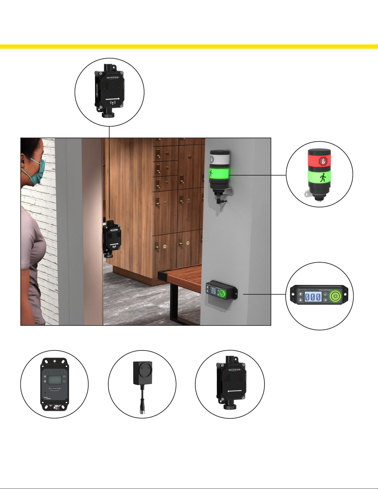
Mount the Indicator Light indoors when
possible and mount so that people entering
the monitored area are able to see the
occupancy status.
Mount the indicator light using the supplied
bracket and ¼-20 mounting bolts, self
tapping screws, or optional magnetic
mounts listed at the end of this document.
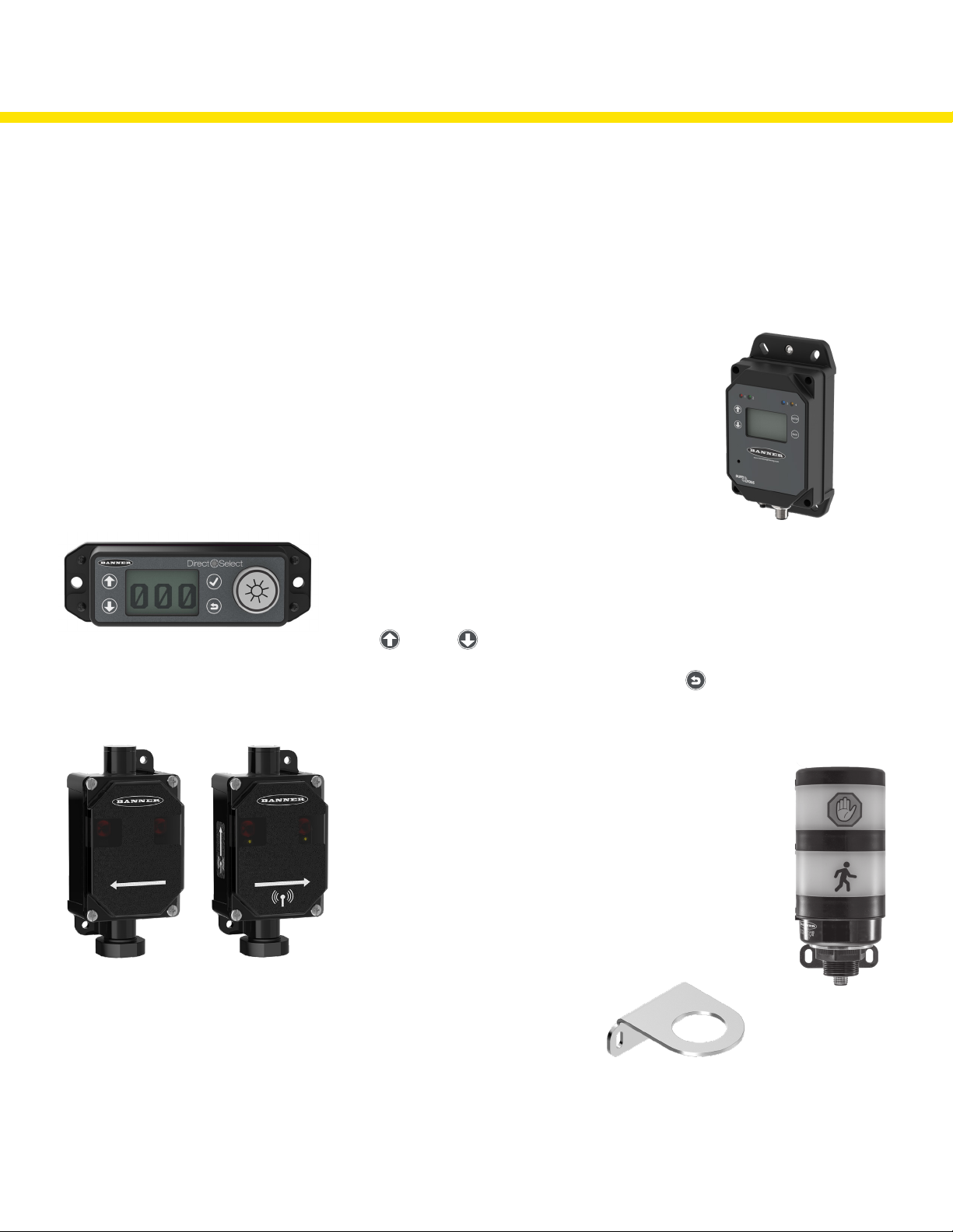
Mount the DXM Controller in a secure
location, outside of any metal cabinets or
enclosures.
The DXM Controller has four mounting
holes. Use ¼-20 mounting bolts or self
tapping screws to secure the controller to
a rigid surface.
The Operator Interface can be mounted near each monitored door, in a central supervisory
location, or can be held by an employee to actively monitor the occupancy level.
Mount the Operator Interface to a rigid surface using the mounting holes and ¼-20 bolts,
self tapping screws, or optional magnetic mounts listed at the end of this document.
How you mount your sensor varies based on the application requirements. User-provided custom mounting fixtures may be
required in cases where the supplied brackets are not compatible with the installation location. Contact your local distributor or
Banner Engineering’s Technical Support team at 1-800-203-5616 for more options or refer to our Troubleshooting section on page
9.
When mounting the Directional Sensor Pair, Banner recommends the sensors be
mounted indoors when possible. The arrows on the face of the Emitter-Receiver Sensor
Pair must point towards the inside of the building/monitored area. Mount the sensors
using two 1/4”-20 mounting bolts, self tapping screws, or the optional magnetic brackets.
Use the side arrows on the Emitter and Receiver to mount the sensor in the correct
orientation.
When mounting the Directional Sensor Pair using the supplied brackets:
1. Mount the Emitter bracket to a rigid surface.
2. Mount the Receiver bracket at the same height as the Emitter bracket. Follow the
bracket assembly instructions on page 4 to re-assemble the Sensors to the bracket.
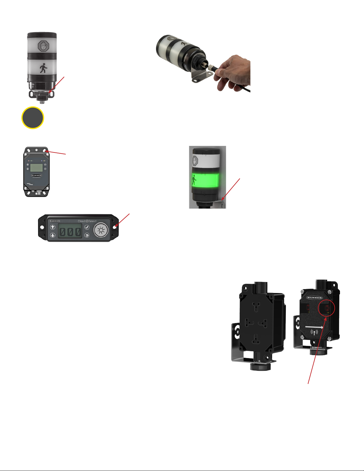
3. Align the Receiver by rotating the housing until it is perpendicular to the Emitter. Two
yellow alignment LEDs should begin to flash on the Receiver when it is aligned.
When mounting the Directional Sensor Pair using the sensor housing mounting holes:
1. Mount the Emitter against a flat surface using the two mounting holes.
2. Place the Receiver across from the Emitter and position it at the same height as the Emitter. Move
the Receiver horizontally until the two yellow Alignment LEDs begin to flash.
3. Secure the Receiver after it has been aligned to the Emitter.
2. Connect the power supply to the
Indicator Light, aligning the keys in the
connector. Hand tighten.
3. Connect the power supply into a
power outlet using the appropriate
regional wall adapter.
Supply Power to the TL70 Wireless Indicator Light and Mount to the Bracket
1. Position the Indicator Light on the
bracket so that the icons are facing
the desired orientation.
Secure with the supplied lock nut.
Hand tighten only.
Mounting Recommendations
• Mount the Directional Sensor Pair so that the sensor’s top is at a minimum height of 1.25 m (50 in) to avoid the potential for miscounts.
Mounting the sensor at a height below 1.25 m (50 in) may result in double counts by detecting arm or leg motion. The Directional
Sensor Pair may need to be mounted higher than 1.25 m (50 in) to avoid counting arm motion or people carrying or pushing objects.
• Mount the Emitter and Receiver less than 30 ft from each other for optimal performance.
Yellow alignment LED