manuals.online logo
Brands
  1. Home
  2. •
  3. Brands
  4. •
  5. BAPI
  6. •
  7. Transmitter
  8. •
  9. BAPI BAPI-Stat Quantum Slim Owner's manual

BAPI BAPI-Stat Quantum Slim Owner's manual

BAPI-Stat “Quantum Slim” Wireless Room
Temperature Transmitter
Building Automation Products, Inc., 750 North Royal Avenue, Gays Mills, WI 54631 USA
Tel:+1-608-735-4800 • Fax+1-608-735-4804 • E-mail:[email protected] • Web:www.bapihvac.com
Specications subject to change without notice.
1 of 4
Installation & Operations
39907_ins_wireless_QuantumSlim rev. 02/07/18
Overview and Identication
Fig. 1: BAPI-Stat “Quantum Slim” Room Transmitter and Hanging Bracket and Remote Sensors
Associated Gateway/Receiver
The Gateway receives the data from transmitters up to 275 feet away, and provides the data
to the BAS via multiple communication options (TCP/IP, JSON, BACnet IP). The Gateway also
sends a conrmation signal to each transmitter upon a successful reception of data, allowing
the transmitter to release the data that it has stored in memory so that no data is lost during
a signal interruption. Operation of the Gateway is described in the Gateway
instruction sheet (39021_RCV_900_BACnet.pdf) Fig. 2:
Gateway/Receiver
External Remote
Probe Sensor
External Hanging
Thermobuffer Sensor
BAPI-Stat “Quantum Slim”
The BAPI-Stat “Quantum Slim” Wireless Temperature Transmitter is designed to monitor temperature inside
refrigerator and freezer cases. The unit mounts on the outside of freezer units and can be mounted either inside or
outside of refrigerator units. It is available with an internal or an external sensor.
The external sensor’s ribbon cable can easily t between the door seal or through hole with FEP cable without affecting
appliance efciency. The temperature is then transmitted to the receiver with a measurement range of -40 to 185˚F
(-40 to 85˚C). The unit has an estimated battery life of 5 years with the default transmit rate of once every 5 minutes.
The unit has an estimated battery life of 5 years with the default transmit rate of once every 5 minutes. The transmitted
temperature is picked up by a Receiver/Gateway and supplied directly to the BAS
via
multiple communication options
(TCP/IP, JSON, BACnet IP). The transmitter stores all data in memory until it receives a successful reception signal
from the Receiver/Gateway, so that no data is lost during a signal interruption. Transmissions can also be triggered
by a temperature change with a user-adjustable threshold. The 902 MHz signal is “frequency agile” for maximum
reliability.
BAPI-Stat “Quantum Slim” Wireless Room
Temperature Transmitter
Building Automation Products, Inc., 750 North Royal Avenue, Gays Mills, WI 54631 USA
Tel:+1-608-735-4800 • Fax+1-608-735-4804 • E-mail:[email protected] • Web:www.bapihvac.com
Specications subject to change without notice.
2 of 4
Installation & Operations
39907_ins_wireless_QuantumSlim rev. 02/07/18
Initial Activation
Fig. 6: Cover
removed from
base plate on
battery power
unit
Fig. 7: Battery
insulator tab
removal
1. Place the base plate against the wall where you want to mount the
sensor and mark the two mounting holes.
2. Drill two 3/16” holes in the center of each marked mounting hole. Insert
a drywall anchor into each hole.
3. Secure the base to the drywall anchors using the #6 x 1 inch mounting
screws provided.
4. Attach Cover by latching it to the top of the base, rotating the cover
down and snapping it into place. Secure the cover by backing out the
lock-down screws using a 1/16” Allen wrench until they are ush with the
bottom of the cover.
5. For units with an internal sensor the mounting process is complete.
6. For remote sensors, string the wire through the freezer door and place
the sensor in the best location to measure the required temperature.
7. Mount the External Probe using a Flexible Probe Bracket (Fig. 4) or use
the clip or screw hole on the Hanging Bracket Sensor (Fig. 5)
Fig. 3: BAPI-Stat “Quantum Slim” Mounting
Drywall Mounting
Fig. 4: External Probe Mounting with a
Flexible Probe Bracket (BA/FPB)
Fig. 5: External
Hanging Bracket
Sensor Mounting
1. Cover Removal: Remove the cover from the base
plate by turning in the cover lockdown screw with
a 1/16” Allen wrench (as described in the Mounting
Section) until the cover can be removed (Fig 6).
2. Battery Tab Insulator Removal for Battery Power
Units: If the unit is ordered with battery power, it will
come with two pre-installed batteries. To activate
the unit, nd the battery tab insulators and pull
them out (Fig. 7). The unit will begin transmitting at
approximately 5 minute intervals.
3. Applying Power to Wired Units: If the unit is
ordered with wired power, it will have a power
terminal block near the top center of the unit. To
activate the unit, apply 9 to 30 VDC (50 mA max)
or 15 to 28 VAC (50 mA max) (Fig. 9). The unit will
begin transmitting at approximately 5 minute intervals
after power is applied.
4. Cover Replacement: Attach Cover by latching it
to the top of the base, rotating the cover down and
snapping it into place. Secure the cover by backing
out the lock-down screws using a 1/16” Allen wrench
until they are ush with the bottom of the cover.
Fig. 9: Power
applied to
terminal block
Fig. 8: Cover
removed from
base plate on
battery power
unit
BAPI-Stat “Quantum Slim” Wireless Room
Temperature Transmitter
Building Automation Products, Inc., 750 North Royal Avenue, Gays Mills, WI 54631 USA
Tel:+1-608-735-4800 • Fax+1-608-735-4804 • E-mail:[email protected] • Web:www.bapihvac.com
Specications subject to change without notice.
3 of 4
Installation & Operations
39907_ins_wireless_QuantumSlim rev. 02/07/18
Pressing the “Ping/Train”
button on the circuit board
will force a transmission.
Note: The unit is factory set to
transmit once every 5 minutes.
The transmission rate can be
changed via the receiver/gateway
network interface (as described
in the gateway instruction sheet
(39021_RCV_900_BACnet.pdf).
Operation
Fig. 12: BAPI-Stat “Quantum
Slim” Circuit Board for Battery
Power Units
Battery Replacement
1. Cover Removal: Remove the cover from the base
plate by turning in the cover lockdown screw with
a 1/16” Allen wrench (as described in the Mounting
Section) until the cover can be removed (Fig 6).
2. Battery Replacement: Remove the batteries from
their holders and discard (Fig. 10). Replace with
new batteries in the correct orientation (Fig. 11).
3. Cover Replacement: Attach Cover by latching it
to the top of the base, rotating the cover down and
snapping it into place. Secure the cover by backing
out the lock-down screws using a 1/16” Allen
wrench until they are ush with the bottom of the
cover. Fig. 10: Battery removal Fig. 11: Battery replacement
Install the provided
batteries. It will begin
transmitting when
power is applied.
Pressing the “Ping/Train”
button on the circuit board
will force a transmission.
Note: The unit is factory set to
transmit once every 5 minutes.
The transmission rate can be
changed via the receiver/gateway
network interface (as described
in the gateway instruction sheet
(39021_RCV_900_BACnet.pdf).
Fig. 13: BAPI-Stat “Quantum
Slim” Circuit Board for Wired
Power Units
The unit is powered by 9 to
30 VDC (50 mA max) or 15
to 28 VAC (50 mA max). It
will begin transmitting when
power is applied.
BAPI-Stat “Quantum Slim” Wireless Room
Temperature Transmitter
Building Automation Products, Inc., 750 North Royal Avenue, Gays Mills, WI 54631 USA
Tel:+1-608-735-4800 • Fax+1-608-735-4804 • E-mail:[email protected] • Web:www.bapihvac.com
Specications subject to change without notice.
4 of 4
Installation & Operations
39907_ins_wireless_QuantumSlim rev. 02/07/18
FCC Wireless Certication and Interference Statement
Wireless BAPI-Stat “Quantum Slim” Room Transmitter (QSL900) - FCC ID: T4FQSL900
This equipment has been tested and found to comply with the limits for a class B digital device, pursuant to part 15 of
the FCC Rules. These limits are designed to provide reasonable protection against harmful interference in a residential
installation. This equipment generates, uses, and can radiate radio frequency energy, and if not installed and used in ac-
cordance with the instructions, may cause harmful interference to radio communications. However, there is no guarantee
that interference will not occur in a particular installation. If this equipment does cause harmful interference to radio or
television reception, which can be determined by turning the equipment off and on, the user is encouraged to try to correct
the interference by one or more of the following measures:
• Reorient or relocate the receiving antenna.
• Increase the separation between the equipment and receiver.
• Connect the equipment into an outlet on a circuit different from that to which the receiver is connected.
• Consult the dealer or an experienced radio / TV technician for help.
In order to maintain compliance with FCC regulations, shielded cables must be used with this equipment. Operation with
non-approved equipment or unshielded cables is likely to result in interference to radio and TV reception. The user is
cautioned that changes and modications made to the equipment without the approval of the manufacturer could void the
user’s authority to operate this equipment.
Possible Problems:
Temperature value is not
being received properly by
the Gateway
Sensor is not
communicating with the
Gateway
Diagnostics
Possible Solutions:
Verify that the controller’s software is congured properly.
Make sure the transmitters are within range of the receiver/gateway.
Verify proper power and termination of the receiver/gateway as shown in the Gateway/
Receiver instructions document “39021_RCV_900_BACnet.pdf” available on the BAPI
website or by contacting BAPI.
Check that the receiver/gateway’s yellow LED to the left of the Ethernet cable jack is
illuminated and that the green LED to the right is blinking indicating a good Ethernet
network connection and network activity.
Perform the “Wireless Sensor Reset” procedure as described above and in the Gateway
instructions document “39021_RCV_900_BACnet.pdf” available on the BAPI website or
by contacting BAPI.
Wireless Sensor Reset
Pressing the “Ping/Training” button on a wireless sensor for 15 seconds will reset the sensor to the original factory
default settings (which are accessed through the associated Gateway receiver). This reset procedure can be used to
re-establish communication between the sensor and the Gateway if communication is lost due to mismatched
addresses. The address of the sensor will be reset to the default: 42415049. This default address can then be entered
for the Gateway (as described in the Gateway instructions document “39021_RCV_900_BACnet.pdf”) to re-establish
communication with the sensor. Once communication is established, the address of the Gateway and the sensor can
be returned to the previous address to re-establish communication with the other sensors on the network (as described
in the Gateway instructions document “39021_RCV_900_BACnet.pdf”).
Besides reseting the wireless address, the reset procedure will also return the sensor to these default values:
Channel = 1, 3 • Transmit power = 0 dBm • Reported intervals = 300 seconds • Sample Interval = 300 seconds
• AES key = not affected by the reset procedure • Battery warning Voltage = 2.5 • All offsets = 0

Other BAPI Transmitter manuals

BAPI H200 User manual

BAPI

BAPI H200 User manual

BAPI Wireless Room Temperature and Humidity... User manual

BAPI

BAPI Wireless Room Temperature and Humidity... User manual

BAPI 418MHz User manual

BAPI

BAPI 418MHz User manual

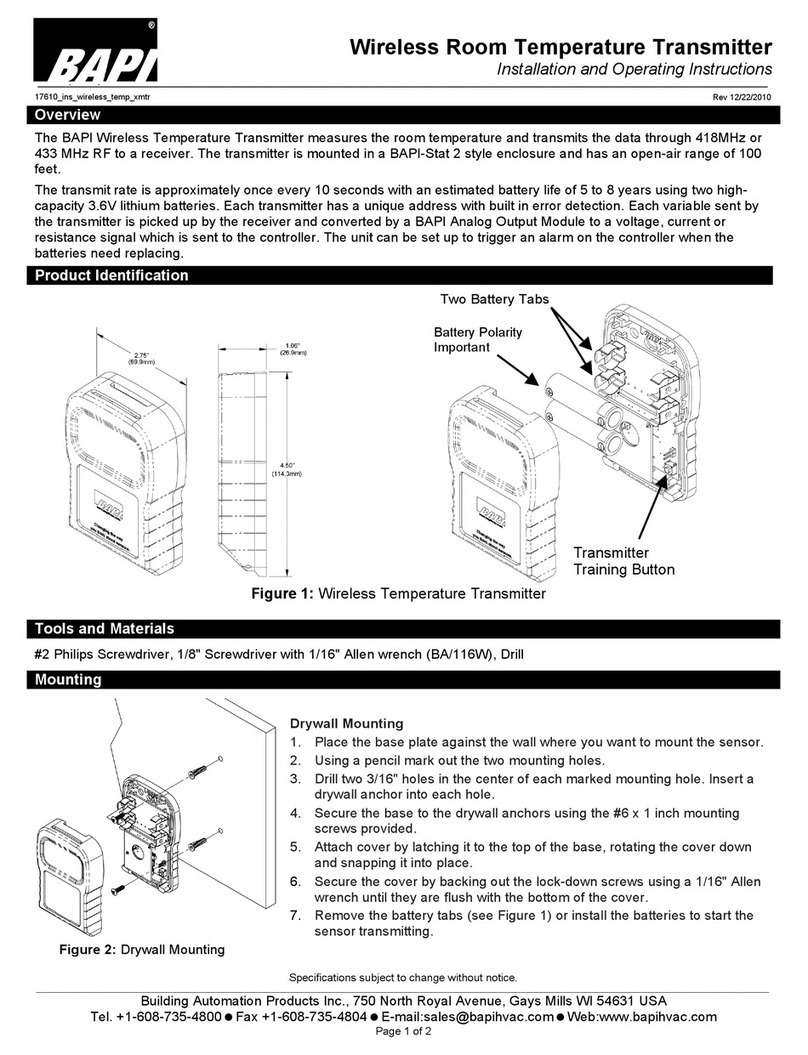
BAPI Wireless Room Temperature Transmitter User manual

BAPI

BAPI Wireless Room Temperature Transmitter User manual

BAPI Delta Style User manual

BAPI

BAPI Delta Style User manual

BAPI BA/T100 Manual

BAPI

BAPI BA/T100 Manual

Popular Transmitter manuals by other brands

evertz 7700 Series manual

evertz

evertz 7700 Series manual

VARIZOOM VZ-WFF instruction manual

VARIZOOM

VARIZOOM VZ-WFF instruction manual

Elenos ETG300 User and maintenance manual

Elenos

Elenos ETG300 User and maintenance manual

RFL Communications 67 PLC 48 DC Manual of instructions

RFL Communications

RFL Communications 67 PLC 48 DC Manual of instructions

Nolan NSTX5C2XXX user guide

Nolan

Nolan NSTX5C2XXX user guide

Platinum Z5 CD manual

Platinum

Platinum Z5 CD manual

Siemens SITRANS DS III series Compact operating instructions

Siemens

Siemens SITRANS DS III series Compact operating instructions

Retekess TR508 instruction manual

Retekess

Retekess TR508 instruction manual

TESTO 915i instructions

TESTO

TESTO 915i instructions

Lightware DVI-OPT-RX110 quick start guide

Lightware

Lightware DVI-OPT-RX110 quick start guide

Emerson Rosemount 5408 Reference manual

Emerson

Emerson Rosemount 5408 Reference manual

Telex WT-450 operating instructions

Telex

Telex WT-450 operating instructions

ALFAtron SMW42S Command guide

ALFAtron

ALFAtron SMW42S Command guide

Emerson Rosemount 2051G quick start guide

Emerson

Emerson Rosemount 2051G quick start guide

Voyager WVOS2TX Installation and operation manual

Voyager

Voyager WVOS2TX Installation and operation manual

BWI Eagle AIR-EAGLE XLT Product information bulletin

BWI Eagle

BWI Eagle AIR-EAGLE XLT Product information bulletin

OWL Intuition-lc Getting started

OWL

OWL Intuition-lc Getting started

Raptor R56 Additional operating instructions

Raptor

Raptor R56 Additional operating instructions

manuals.online logo
manuals.online logoBrands
  • About & Mission
  • Contact us
  • Privacy Policy
  • Terms and Conditions

Copyright 2025 Manuals.Online. All Rights Reserved.