Barco CineVersum 120 User manual

HOME CINEMA
CINEVERSUM SYSTEM
R9010090
OWNERS MANUAL
Cine VERSUM 120
01102003 R5976667/00

Barco nv Home Cinema
Noordlaan 5, B-8520 Kuurne
Phone: +32 56.36.84.30
Fax: +32 56.36.88.62
E-mail: [email protected]
Visit us at the web: www.homecinema.barco.com
Printed in Taiwan

Changes
Barco provides this manual ’as is’ without warranty of any kind, either expressed or implied, including but not limited to the implied war-
ranties or merchantability and fitness for a particular purpose. Barco may make improvements and/or changes to the product(s) and/or the
program(s) described in this publication at any time without notice.
This publication could contain technical inaccuracies or typographical errors. Changes are periodically made to the information in this
publication; these changes are incorporated in new editions of this publication.
Copyright ©
All rights reserved. No part of this document may be copied, reproduced or translated. It shall not otherwise be recorded, transmitted or
stored in a retrieval system without the prior written consent of BARCO.
Trademarks
Brand and product names mentioned in this manual may be trademarks, registered trademarks or copyrights of their respective holders.
All brand and product names mentioned in this manual serve as comments or examples and are not to be understood as advertising for
the products or their manufactures.
Federal Communication Commission (FCC Statement)
This equipment has been tested and found to comply with the limits for a class B digital device, pursuant to Part 15 of the FCC rules.
These limits are designed to provide reasonable protection against harmful interference when the equipment is operated in a residential
environment. This equipment generates, uses, and can radiate radio frequency energy and, if not installed and used in accordance with the
instruction manual, may cause harmful interference to radio communications. Operation of this equipment in a residential area is likely to
cause harmful interference in which case the user is encouraged to try to correct the interference by one or more of the following measures.
Introduction to the user :
If this equipment does cause interference to radio or television reception, the user may try to correct the interference by one or more of the
following measures :
• Re-orientation of the receiving antenna for the radio or television.
• Relocate the equipment with respect to the receiver.
• Plug the equipment into a different outlet so that the equipment and receiver are on different branch circuits.
• Fasten cables connectors to the equipment by mounting screws.
The use of shielded cables is required to comply within the limits of Part 15 of FCC rules and EN55022.
Guarantee and Compensation
Barco provides a guarantee relating to perfect manufacturing as part of the legally stipulated terms of guarantee. On receipt, the purchaser
must immediately inspect all delivered goods for damage incurred during transport, as well as for material and manufacturing faults Barco
must be informed immediately in writing of any complaints.
The period of guarantee begins on the date of transfer of risks, in the case of special systems and software on the date of commissioning,
at latest 30 days after the transfer of risks. In the event of justified notice of compliant, Barco can repair the fault or provide a replacement
at its own discretion within an appropriate period. If this measure proves to be impossible or unsuccessful, the purchaser can demand a
reduction in the purchase price or cancellation of the contract. All other claims, in particular those relating to compensation for direct or
indirect damage, and also damage attributed to the operation of software as well as to other services provided by Barco, being a component
of the system or independent service, will be deemed invalid provided the damage is not proven to be attributed to the absence of properties
guaranteed in writing or due to the intent or gross negligence or part of Barco.
If the purchaser or a third party carries out modifications or repairs on goods delivered by Barco, or if the goods are handled incorrectly,
in particular if the systems are commissioned operated incorrectly or if, after the transfer of risks, the goods are subject to influences not
agreed upon in the contract, all guarantee claims of the purchaser will be rendered invalid. Not included in the guarantee coverage are
system failures which are attributed to programs or special electronic circuitry provided by the purchaser, e.g. interfaces. Normal wear as
well as normal maintenance are not subject to the guarantee provided by Barco either.
The environmental conditions as well as the servicing and maintenance regulations specified in the this manual must be complied with by
the customer.


Table of contents
TABLE OF CONTENTS
1. SafetyInstructions..................................................................................................3
1.1 General Safety Instructions . ............................................................................................................ 3
1.2 Module Related Safety Instructions .................................................................................................... 3
1.2.1 Cine VERSUM 120............................................................................................................... 3
1.2.2 Cine VERSUM Master ...........................................................................................................4
2. SystemConfiguration.............................................................................................. 5
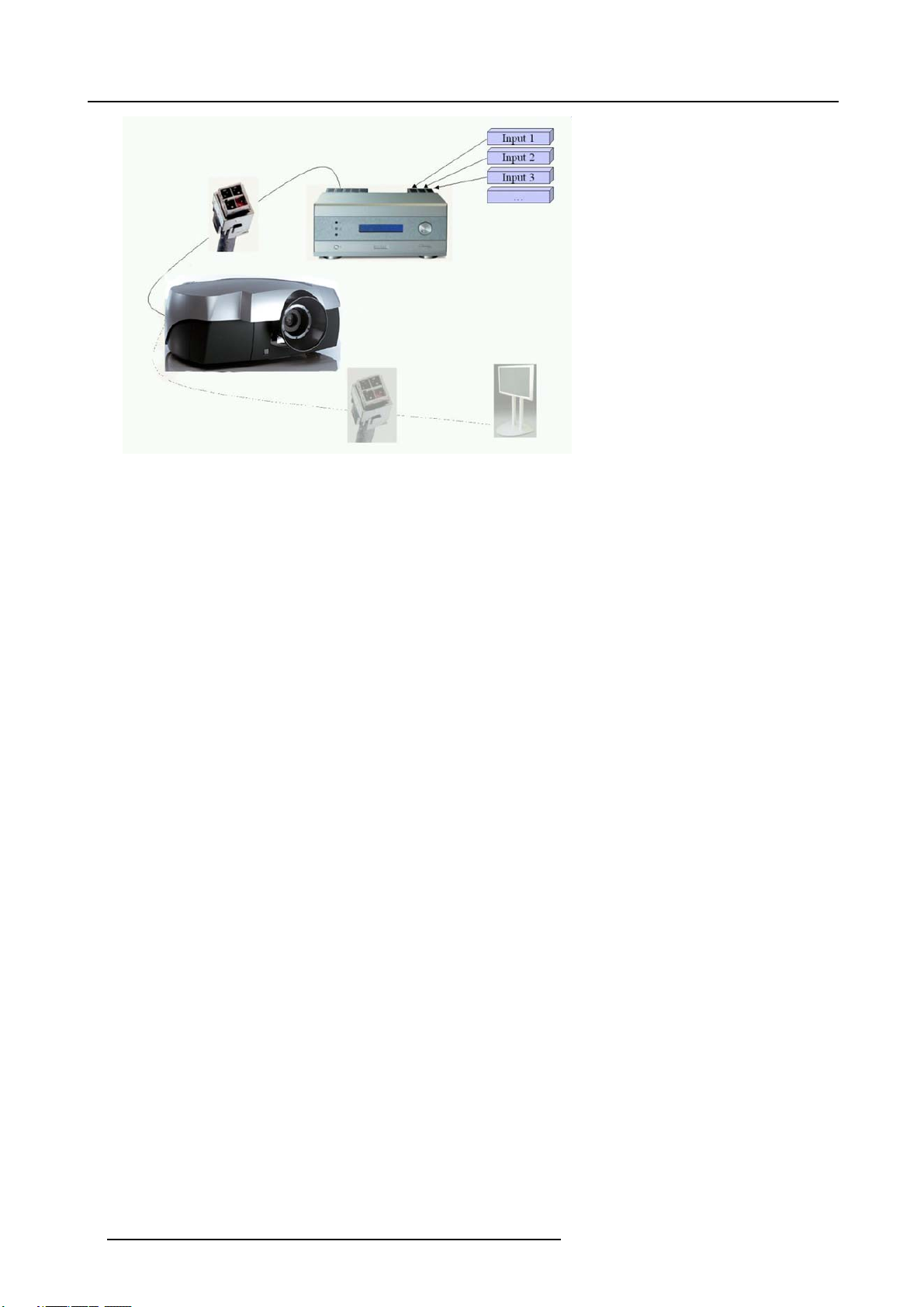
2.1 The Video Distribution Solution......................................................................................................... 5
2.2 Overview of the System ................................................................................................................ 5
3. OverviewUser’sControls..........................................................................................7
3.1 Cine VERSUM Master.................................................................................................................. 7
3.2 Cine VERSUM 120 ..................................................................................................................... 7
3.3 Remote Control ......................................................................................................................... 8
3.4 Remote Control operation . . ...........................................................................................................10
3.4.1 General ..........................................................................................................................10
3.4.2 Battery Insertion in the Remote Control ........................................................................................ 11
3.4.3 Visualization of commands......................................................................................................13
4. Switching On/Offthe CineVersumSystem....................................................................15
4.1 Brief introduction . . . . ...................................................................................................................15
4.2 Upon first startup.......................................................................................................................15
4.3 Switching the system between OPERATION and STANDBY ........................................................................16
4.3.1 From OPERATION mode to STANDBY mode .................................................................................16
4.3.2 From STANDBY mode to OPERATION mode .................................................................................17
4.4 Switching the system between STANDBY and ECONOMIC Standby . ..............................................................17
4.4.1 From STANDBY mode to Economic STANDBY................................................................................18
4.4.2 From Economic STANDBY mode to STANDBY. . . .............................................................................18
4.5 Switching the system OFF completely and BACK to Operation mode...............................................................18
4.5.1 Turning OFF the system from Operation mode ................................................................................19
4.6 Turning ON the system from total OFF mode.........................................................................................19
5. Directsourceselection............................................................................................21
5.1 From standby mode. ...................................................................................................................21
5.2 Return to standby mode ...............................................................................................................22
6. ImageControl.......................................................................................................23
6.1 Brightness Control .....................................................................................................................23
6.2 Contrast Control........................................................................................................................23
6.3 Color (Saturation) Control .............................................................................................................24
6.4 Tint control .............................................................................................................................25
7. Picture in Picture...................................................................................................27
7.1 Turning On/Off the Picture in Picture..................................................................................................27
7.2 Selecting Input Source for PIP Window . . . ............................................................................................28
7.3 Function keys for Picture in Picture ...................................................................................................28
8. LensandLampmanipulations...................................................................................31
8.1 Lens adjustment .......................................................................................................................31
8.1.1 Access to controls...............................................................................................................31
8.1.2 Focus adjustment ...............................................................................................................32
8.1.3 Horizontal shift...................................................................................................................32
8.1.4 Vertical shift......................................................................................................................33
8.1.5 Zoom.............................................................................................................................34
8.2 Lamp ...................................................................................................................................34
8.2.1 Access controls.................................................................................................................. 35
8.2.2 Lamp mode......................................................................................................................35
8.2.3 Lamp power .....................................................................................................................36
9. AspectRatio.........................................................................................................37
9.1 About Aspect Ratios ...................................................................................................................37
9.2 Selecting an Aspect Ratio .............................................................................................................38
Index......................................................................................................................39
R5976667 CINEVERSUM SYSTEM 01102003 1

Table of contents
2R5976667 CINEVERSUM SYSTEM 01102003

1. Safety Instructions
1. SAFETY INSTRUCTIONS
Overview
• General Safety Instructions
• Module Related Safety Instructions
This manual is intended for the user/operator of the installed digital video distribution system. Any change
in cabling or servicing of the installed modules must be performed by service personnel having appropriate
technical training and experience necessary to be knowledgeable of potential hazards to which they are ex-
posed in performing a task, and of measures to minimize the potential risk to themselves or other persons.
1.1 General Safety Instructions
Lightning
For added protection for this video distribution system during a lightning storm, or when it is left unattended and unused for long
periods of time, unplug it from the wall outlet and disconnect the power cord. This will prevent damage to the modules due to a
lightning and power-line surges.
ObjectandLiquidEntry
Never push objects of any kind into the modules through openings as they may touch dangerous voltage points or short-out parts
that could result in a fire or electrical shock. Never spill liquid of any kind on the product.
Servicing
Do not attempt to service the modules yourself as opening or removing covers may expose you to dangerous voltage or other
hazards. Refer all servicing to qualified service personnel.
Damage Requiring Servicing
Unplug the modules from the wall outlet and refer servicing to qualified service personnel under the following circumstances:
• If the power-supply cord or plug is damaged.
• If liquid has been spilled, or objects have fallen into the modules.
• If the module has been exposed to rain of water.
• If the product exhibits a distinct change in performance, this indicates a need for service.
1.2 Module Related Safety Instructions
Overview
• Cine VERSUM 120
• Cine VERSUM Master
1.2.1 Cine VERSUM 120
On cooling
The cooling fans in this projector continue to run for about 1 min. after the projector is turned off. During normal operation, when
turning the power off always use the power down function on the Master or the remote control. Ensure the cooling fan has stopped
before switching off the projector using the power switch.
DURING NORMAL OPERATION, NEVER TURN THE PROJECTOR OFF BY DISCONNECTION THE POWER CORD. FAILURE
TO OBSERVE THIS WILL RESULT IN PREMATURE LAMP FAILURE.
Slots and Openings
Slots and openings in the cabinet and the sides are provided for ventilation; to ensure reliable operation of the projector and to
protect it from overheating, these openings must not be blocked or covered.
Protection from Ultraviolet Radiation
WARNING: DO NOT LOOK DIRECTLY IN THE HIGH INTENSITY LIGHT BEAM. The lamp contained in this product is an intense
source of light and heat. One component of the light emitted from the lamp is ultraviolet light which can damage the eyes.
R5976667 CINEVERSUM SYSTEM 01102003 3

1. Safety Instructions
1.2.2 Cine VERSUM Master
Unit damage
Overheating may lead to the master shutting down during operation.
4R5976667 CINEVERSUM SYSTEM 01102003

2. System Configuration
2. SYSTEM CONFIGURATION
Overview
• The Video Distribution Solution
• Overview of the System
2.1 The Video Distribution Solution
The Cine VERSUM Revolution
Thank you for purchasing the Cine VERSUM system from Barco. You are now at the gates of projection heaven.
The Cine VERSUM from BARCO Home Cinema is the result of a completely new look at home cinema. BARCO has fundamentally
changed the way a home cinema system works, from source to image! We are proud we have fulfilled your demands, with this very
first non-compromise home theater solution ever released.
All the modules of the system form a single transparent solution. The Cine VERSUM Series is not just a new range of products: it
is a future-proof platform that is compatible with all future standards.
What does modular, future-proof, no-compromise mean?
Think of the audio world: in the low end of the market, audio switching, processing and amplification are done within a single unit.
The single unit does it all, and is therefore inherently a compromise “combo”. In the high end of the market however, individual
modules are optimized to do one specific task:
• A pre-amplifier or AV processor.
• A separate power amplifier for all, or multiple power amplifiers for each individual audio channel.
• A digital link between pre- and power amplifier to guarantee a perfect signal transmission.
Barco Home Cinema, with CineVERSUM, brings to the high-end video world what the audio world has been enjoying for many years:
a truly modular solution, with exceptional video quality.
2.2 Overview of the System
Source managing
The Cine VERSUM system allows you to manage your sources in an easy and comfortable way. As the Cine VERSUM Master can
be stored close to your sources, signal loss is limited as much as possible. Once the signal is processed, in a completely digital
way, the high-bandwidth cable allows for non-compromise distribution.
Image 2-1
Source connection
Display linking
Given this one-cable design, we integrated the possibility of chaining multiple display units, one after another. As such, your Cine
VERSUM Master can feed a combination of up to 32 projectors and plasma displays.
R5976667 CINEVERSUM SYSTEM 01102003 5

2. System Configuration
Image 2-2
Display link
6R5976667 CINEVERSUM SYSTEM 01102003

3. Overview User’s Controls
3. OVERVIEW USER’S CONTROLS
Overview
• Cine VERSUM Master
• Cine VERSUM 120
• Remote Control
• Remote Control operation
3.1 Cine VERSUM Master
Front View
The front side of theCine VERSUM Master is provided with the following controls:
Image 3-1
Front side Cine VERSUM Master
Controls function description
Ref. Function Description
1Infra Red Reception LED indicator Lights up when a valid Infra Red signal from the Remote Control has
been captured.
2Infra Red Receiver Reception diode for the Infra Red signals sent by the Remote Control
when a key is pressed.
3Standby LED Blinks when the Cine VERSUM Master has been powered down to
Standby or Economy Standby mode.
4Main power switch (see Switching On/Off the Cine Versum System, page 15)
5LCD Display This display indicates the status of the Cine VERSUM Master and allows
you to navigate through the different menus.
6Selection and Confirmation dial The knob allows to navigate through the different menus.
Table 3-1
3.2 Cine VERSUM 120
Top View
The top side of the Cine VERSUM 120 is provided with the following controls:
R5976667 CINEVERSUM SYSTEM 01102003 7

3. Overview User’s Controls
Image 3-2
Cine VERSUM 120 controls
Controls function description
Ref. Function Description
1Main power switch Button pressed, switches the projector in the ’Standby’ mode. This mode
is indicated by the standby LED which lights up repeatedly 2 times short
on, 1 time long off.
2Infra Red Receiver Reception diode for the IR signals from the Remote Control. Allows
switching On/Off (Standby) of the projector separately and controlling
the Cine VERSUM Master.
3Standby LED Lights up continuously: projector in the operation mode.
Lights up repeatedly 2 times short on, 1 time long off: projector in the
standby mode
Blinks fast: projector in the cooling down mode after switching off
(duration 1 min.).
Lights up repeatedly 1 time long, 1 time short: projector has been started
up in the cooling down mode, waiting for lamp ignition.
4Not used
5Infra Red Reception LED indicator Lights up when a valid IR signal from the Remote Control has been
captured.
Table 3-2
3.3 Remote Control
Top side
The Infra Red Remote Control buttons support the following functionality:
8R5976667 CINEVERSUM SYSTEM 01102003

3. Overview User’s Controls
2
10
11
4
514
6
7
3
12
18
9
Image 3-3
Remote control
Controls function description
Ref. Function Description
1Adjust button To enter the adjustment menus or the leave the adjustment menus. For more
explanation about the adjustment menus, consult the installation manual.
2Address button To match the Remote Control with the unit that you are addressing (number between
0 and 9).
3Pause button To blank the image in the digital link.
4Standby button To power up/down the Cine VERSUM Master and the displays in the link.
5Digit buttons Allows to directly select sources.
6RC operation indication Lights up when a button on the remote control is pressed (Visual indication of remote
control operation – Battery check).
7Function keys The function keys are used in picture in picture (PIP) to position the PIP image.
8EXIT button To go up one step in the menu structure.
9ENTER button To enter the adjustment menus or to confirm an adjustment with the adjustment
menus.
10 TEXT When text is on, press TEXT to switch off OSD display. Press TEXT again, OSD
appears as defined in the OSD configuration window.
11 FREEZE Press to freeze the image
12 * Button Aspect ratio toggle button for the actual image
13 Picture controls Allow to optimize the picture reproduction
Table 3-3
R5976667 CINEVERSUM SYSTEM 01102003 9

3. Overview User’s Controls
Stored sources
The Cine VERSUM Master can be equipped with up to 8 digital and analog input modules. These modules are linked to your sources
and can be selected with the touch of a button on the Remote Control.
The table below allows you to note the stored source per input slot, digit button 1 to 8.
Digit Button Stored source
1
2
3
4
5
6
7
8
3.4 Remote Control operation
Overview
• General
• Battery Insertion in the Remote Control
• Visualization of commands
3.4.1 General
How to use
The Remote Control allows you to control your Cine VERSUM Master, even when it is built into a cabinet. Indeed, the SL/XL cable
allows for 2–way communication. This means you can point the Remote Control to a display unit and still change the settings of the
Cine VERSUM Master.
10 R5976667 CINEVERSUM SYSTEM 01102003

3. Overview User’s Controls
Image 3-4
Master control via 2-way communication SL/XL cable
Backlighting
When a button on the remote control is pressed, backlight is activated automatically. That allows the user to operate the remote
control in a dark room. Backlight is turned off automatically a few seconds after the last button activation.
If backlight and RC operation indicator lights up too long or continuously, batteries need to be replaced.
Factory address setting of the modules
The factory address setting of the modules is as follows:
Module Individual Address Common Address
Cine VERSUM 120 address <9> no common address
Cine VERSUM Master address <1> common address <0>
Common address: is a fixed address, stored in the module. The module will execute the commands sent by
a Remote Control, programmed with the common address <0>.
3.4.2 Battery Insertion in the Remote Control
Where to find the batteries
The batteries are not placed in the remote control to avoid remote control operation in its package, resulting in a shorter battery life
time.
How to install the batteries
1. Push the cover tab (A) with the fingernail a little backwards and pull upwards the cover top (B). (image 3-5)
2. Slide the cover forwards to remove. (image 3-6)
3. Push the battery body towards the spring and lift it up to remove. (image 3-7)
R5976667 CINEVERSUM SYSTEM 01102003 11

3. Overview User’s Controls
4. Insert two AA size batteries, making sure the polarities match the + and – marks inside the battery compartment (image 3-7).
5. Insert the lower tab of the battery cover in the gap at the bottom of the remote control, and press the cover until it clicks in place
(image 3-7).
Image 3-5
Battery cover unlock
Image 3-6
Battery cover removal
Image 3-7
Battery removal
How to reinstall the address
By removing the batteries, the address in the Remote Control will be set to 0. In case the different modules are controlled separately
(own address), the respective address of the module you desire to control has to be set. To reinstall an address, follow procedure
below:
1. Point the Remote Control to the module of which you want to know the address and press the address button (use a pencil).
(image 3-8)
On the screen appears a message box (image 3-9) indicating the address number. In the graphical display of the Cine VERSUM
Master appears the same message (image 3-10).
2. To adapt the address in the Remote Control, cover the IR transmitting diodes and press the address button once, followed within
the 5 seconds by pressing the corresponding digit button, 1 to 8.
Image 3-8 Image 3-9
Message address on-screen
12 R5976667 CINEVERSUM SYSTEM 01102003

3. Overview User’s Controls
Image 3-10
Message address display master
3.4.3 Visualization of commands
How the commands are visualized
When a button on the Remote Control or the dial knob on the Cine VERSUM Master is pressed, the command is visualized on the
screen of the plasma display or of the projector and also on the graphical display of the Cine VERSUM Master. This can take the
form of a menu, a message or a bar scale. Below an illustration of each item:
Image 3-11
On-screenmainmenu
Image 3-12
Main menu on Master display
Image 3-13
On-screen message
Image 3-14
Message on Master display
Image 3-15
On-screen bar scale
Image 3-16
Bar scale on Master display
R5976667 CINEVERSUM SYSTEM 01102003 13

3. Overview User’s Controls
14 R5976667 CINEVERSUM SYSTEM 01102003

4. Switching On/Off the Cine Versum System
4. SWITCHING ON/OFF THE CINE VERSUM SYSTEM
Overview
• Brief introduction
• Upon first startup
• Switching the system between OPERATION and STANDBY
• Switching the system between STANDBY and ECONOMIC Standby
• Switching the system OFF completely and BACK to Operation mode
• Turning ON the system from total OFF mode
4.1 Brief introduction
About the handled system in this manual
The Cine VERSUM is a modular system that provides you the possibility to connect more than one display device to the Cine
VERSUM Master.
In this owner’s manual, we only discuss the most common case : one Master linked to one Projector. For info on the more complex
systems, please review the installation manual.
This is the chapter’s structure:
• Upon first startup
• Switching the system between OPERATION mode and STANDBY
• Switching the system between STANDBY and ECONOMIC STANDBY
• Switching the system OFF completely and BACK TO OPERATION mode.
4.2 Upon first startup
Required steps
There are two steps upon first startup:
1. Press the power switch (A) on the Cine VERSUM Master. (image 4-1)
The Cine VERSUM Master goes from OFF to STANDBY, visualized by blinking of the standby indicator (B).
2. Press the power switch (A) on the Cine VERSUM 120. (image 4-2)
The Cine VERSUM 120 goes from OFF to STANDBY, visualized by blinking of the standby indicator (B).
3. Select “Power up” in the menu on the Cine VERSUM Master, using the jog dial. (image 4-3, image 4-4)
The Cine VERSUM Master and the Cine VERSUM 120 go from STANDBY to operation, visualized by lighting up of the proper
standby indicator (B).
Image 4-1
Cine VERSUM Master
R5976667 CINEVERSUM SYSTEM 01102003 15

4. Switching On/Off the Cine Versum System
Image 4-2
Cine VERSUM 120
Image 4-3
Cine VERSUM Master jog dial
Image 4-4
Power up selection
4.3 Switching the system between OPERATION and STANDBY
Overview
• From OPERATION mode to STANDBY mode
• From STANDBY mode to OPERATION mode
4.3.1 From OPERATION mode to STANDBY mode
Using the Jog dial on the Cine VERSUM Master
1. Press the jog dial once to enter the main menu. (image 4-5)
2. Rotate the jog dial until “Shut down” in the menu is pointed to. (image 4-6)
3. Press jog dial to activate the Shutdown selection.
The Cine VERSUM Master and the Cine VERSUM 120 go from OPERATION to STANDBY. During the power down process, a
power down message appears on-screen and on the Master display. At the end, the Master displays the enter menu screen.
(image 4-7, image 4-8)
16 R5976667 CINEVERSUM SYSTEM 01102003
This manual suits for next models
1
Table of contents
Other Barco Projector manuals

Barco
Barco PGXG-61B User guide

Barco
Barco iD R600+ User manual

Barco
Barco Duet II User manual

Barco
Barco R9002327 User manual

Barco
Barco R9000893 User manual

Barco
Barco MCM-100S User manual

Barco
Barco OV-513 User manual

Barco
Barco RLM W8 User manual

Barco
Barco R5975039 User manual

Barco
Barco R9040100 User manual

Barco
Barco CLM HD8 User manual

Barco
Barco R9002390 User manual

Barco
Barco RLM-W14 User manual

Barco
Barco OV-715 User manual

Barco
Barco CLM HD8 R9050130 User manual

Barco
Barco SIM 7C R9011206 User manual

Barco
Barco RLM series User manual

Barco
Barco RLM W8 User manual

Barco
Barco iCon H600 User manual

Barco
Barco R9001190 User manual