Barker VIP 3500 User manual

(+)
30
AMP
VIP 3500 POWER JACK OWNER'S INSTRUCTIONS
P/Ns 30828, 30900, 31558 (WHITE) and P/Ns 32454, 32455 (BLACK)
GENERAL SAFETY:
Read and understand the Jack installation instructions. Always block trailer wheel when using the jack. Since there are moving parts inside the jack, be
careful of loose clothing, remove or secure loose jewelry (watches, rings, etc.).
30 amp slow blow fuse
VIP Jack travel trailer
battery
Connect the lead-wire directly to the positive (+) lead of
the travel trailer's battery using a twelve (12) gage wire.
Be sure the connection is a good one. THE 30AMP
SLO-BLO FUSE MUST BE INSTALLED AS SHOWN.
INSTALLATION:
IMPORTANT NOTICE:
If it is necessary to change the position of the powerhead relative to the post and flange (in order to provide clearance between powerhead and LP gas bottle
or LP gas cover, or more clearance between the lift gate and the powerhead) loosen set screws and rotate head without lifting off coupling. Retighten
set screws when head is in desired position.
BEFORE INSTALLATION:
Raise your travel trailer's front end and place blocks or stabalizing jacks
under the front "A" frame. Lower the trailer until it rests securely on
stabilizing jacks or blocks. Retract present jack and remove.
H&H Engineering VIP 3,500 Power Jack is designed to lift up to 3,500 pounds a full 18". It's design also includes a night light, attached foot plate, and an
emergency crank handle. An important part of owning and using a VIP Jack is being sure it is properly installed and serviced.
Remove present
jack
"A" frame coupler
IMPORTANT
To insure a good
electrical ground an
internal tooth lock-
washer must be in
place for this bolt.
Make sure powdercoat
or paint is removed from
"A" frame coupler under
washer and that tagged
hole is used.
The bolts should
already be on
your trailer.
Install Jack in hole and secure with 3 bolts & 3 internal tooth lockwashers (bolt holes are threaded). The 3 bolts should already be
on your trailer. The 3 internal lockwashers are supplied by us (in hardware bag). Attach the foot plate to VIP Jack with .50-20 bolt
and .50" lockwasher (supplied in hardware bag).
VIP
SERIES
3000
30 0 0 0 L B S C A P A C I T Y
INITIAL SET-UP AND HOW TO USE YOUR VIP POWER JACK LEVEL:
1. Install your VIP Power Jack (SEE INSTALLATION PAGE 1).
2. Place a small level inside your RV on a surface you want to level. This might be a counter top or freezer compartment of a refrigerator.
NOTE: It will be necessary to move this level to check side to side and front to back condition.
3. Check the "inside level", level your trailer from side to side with stabilizing jacks or boards under the wheels.
4. Checking the "inside level", level your trailer front to back using your VIP Power Jack.
5. Carefully adjust the 3 stainless steel screws on the ring that surround the built in bulls-eye level (see picture) until the air bubble is inside the middle
circle. Your trailer will then be leveled. In the future, you can do all your
leveling by using your VIP Power
Jack built-in level.
Bulls-eye Level
Retaining Ring
Stainless Steel Screws
B A R K E R M F G . B A T T L E C R E E K
POWER
SERIES
3000
High
3 0 0 0 0 L B S C A P A C I T Y
Sticker indicates
the “lock position”
of the level assembly.
MAINTENANCE:
Once a year, the powerhead should be removed and a liberal amount
of grease (preferably a grease with high melting point) applied directly
to the coupling on which the drive pin rests.
DO NOT POUR OIL into top of the jack post.
Once a year, the housing cover should be removed and the gears
inspected for proper lubrication.
Remove 4 screws and tap around edge of housing to free cover.
DO NOT insert screw driver blade! (This may damage mating
surfaces.)
Before replacing cover, clean matging surfaces.
If lubrication is needed, use Mobilith 460 grease or equivalent.
OPERATION (ELECTRIC)
REMEMBER TO KEEP HANDS AND FEET FROM UNDER
THE FOOT PLATE WHEN USING POWER JACK.
When VIP Jack reaches the end of it's travel (either
raising or lowering), the internal clutch activates.
Dolly wheels are not recommended.
Warning
AVOID THE RISK OF INJURY OR DEATH TO YOURSELF AND OTHERS:
USE THE JACK FOR LIFTING THE TRAVEL TRAILER ONLY.
.NEVER GET BENEATH THE TRAILER WHEN IT IS SUPPORTED BY THE JACK.
.SUPPORT THE VEHICLE WITH THE APPROPRIATE MEANS.
.
OPERATION (MANUALLY):
WARNING!!!
Do not use toggle switch with
crank handle in place.
Breaking this rule will cause
serious injury or death.
REMEMBER TO KEEP HANDS AND FEET OUT FROM UNDER
THE FOOT PLATE WHEN USING THE POWER JACK!!
DOLLY WHEELS ARE NOT RECOMMENDED.
BREAKING THESE RULES WILL CAUSE SERIOUS INJURY OR
DEATH.
WARNING
19989
Don't risk serious injury or
death in a shearing or
squeezing accident. Keep
body, hands, and feet away.
VIP 3500 POWER JACK OWNER'S INSTRUCTIONS
P/Ns 30828, 30900, 31558 (WHITE) and P/Ns 32454, 32455 (BLACK)
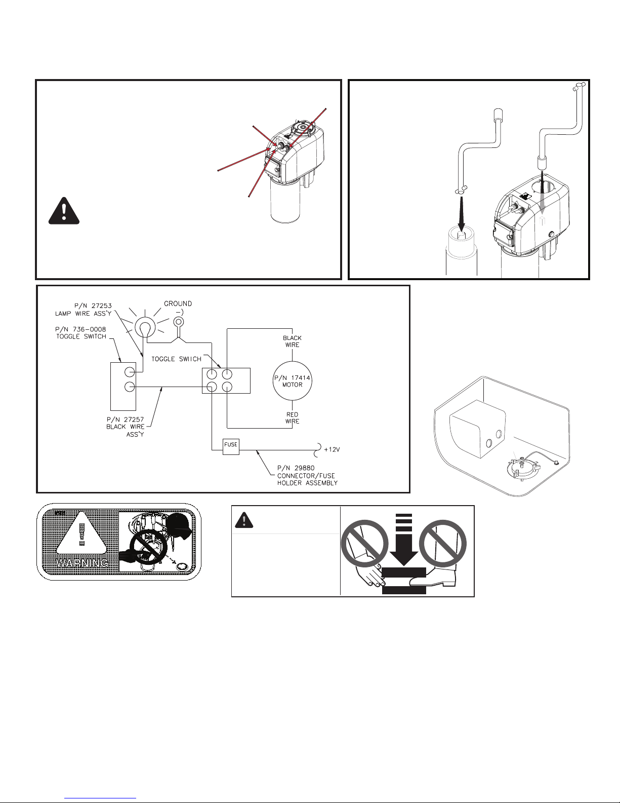
If an electrical failure should occur,
the emergency handle may be in-
serted into the jack post and the
jack can be raised or lowered.
(Access can be obtained by twist-
ing cap off. NOTE: You do not
have to remove or loosen
screws on level to remove the
level assembly.) If the power-
head is removed, crank can
still be used to raise and
lower jack.
..
The JACK will raise and
lower by this
toggle switch--
NOT the travel trailer.
The "night-light" is
controlled by this
toggle switch
UP
DOWN
BARKERMANUFACTURING
P/NXXXXX
Performance
SERIES
3000
High
SCHEMATIC WIRING DIAGRAM
P/N 736-2300
STRAPATTACHMENT:
1. Press strap (1) onto the stud (2) at
the bottom of the cap.
2. Press the retaining ring (3) on stud
(2) snug it down against the strap (1).
3. Repeat this process (4) on the stud
found on the inside of the cover.
THIS WILL SECURE YOUR CAP.
2
314
COVER,
INSIDE
BOTTOM OF CAP
BARKER MFG. BATTLE CREEK
HIGH POWER
SERIES
3000
30000LBS CAPACITY

VIP 3500 POWER JACK OWNER'S INSTRUCTIONS
P/Ns 30828, 30900, 31558 (WHITE) and P/Ns 32454, 32455 (BLACK)
ITEM PART# REQ'D DESCRIPTION
1 30683 1 LOCK INDICATOR LABEL (WHITE)
1 30341 1 LOCK INDICATOR LABEL (BLACK)
2 30331 1 CAPASS'Y (WHITE)
2 30330 1 CAPASS’Y (BLACK)
3 619-0003 3 LOCKWASHER INTERNAL TOOTH
4 736-2300 1 TOGGLE SWITCH
5 736-0008 1 TOGGLE SWITCH
6 606-5001 2 SCREW #10 X .50 PHILLIPS HEAD
7 16392 2 CABLE TIE
8 617-0009 1 THRUST WASHER
9 17419 1 COVER, MACHINED
9 30774 1 COVER, FINISHED (BLACK)
10 29306 1 GASKET
11 28207 1 DRIVE GEAR ASSEMBLY
12 28487 1 TORQUE LIMITER
13 30783 1 BASE FINISHED (WHITE)
13 30782 1 BASE FINISHED (BLACK)
14 608-0006 3 SET SCREW .63-18 X .50
15 618-1002 1 LOCKWASHER .50
16 27257 1 BLACK WIRE ASS'Y
17 17808 1 WIRE CLAMP
18 27262 1 LENS
19 27344 1 MOTOR SLEEVE (WHITE)
19 27276 1 MOTOR SLEEVE (BLACK)
20 26236 1 RUBBER GROMMET
21 17414 1 ELECTRIC MOTOR
22 611-2100 2 HEX LOCK NUT
23 605-0012 4 SCREW
24 27274 1 MOTOR SEAL
25 27338 1 COVER WHITE MACHINED
25 27259 1 COVER BLACK MACHINED
26 80208 1 WASHER, SPACER
27 29880 1 CONNECTOR/FUSE HOLDER ASS'Y
28 623-1216 1 GROOVE PIN
29 30837 1 COVER LABEL
30 606-0010 2 #10-16 X .75 TEK SCREW (ZINC PLATED)
30 606-0008 2 #10-16 X .75 TEK SCREW (BLACK HEAD)
31 27313 1 POSTASS'Y -18" BLACK
31 31367 1 POSTASS'Y- 24" BLACK
32 600-0011 1 HEX BOLT .50-20 X .75
33 80501 2 BUSHING
34 645-0024 1 FLANGE BUSHING
35 641-0009 1 BUSHING
36 603-5016 2 SCREW #10-32 X .75” PHILLIPS
37 16434 2 HOLE PLUG
38 621-0004 2 DOWEL Ø.13" X .75 DOWEL
39 27253 1 LAMP WIRE ASSEMBLY
40 30313 1 LENS GASKET
41 634-0028 1 RETAINING RING
42 26097 1 STRAP
43 21349 1 BASE
44 28259 1 CRANK HANDLE
20 9
10
35
11
26 38
33
22
23
34
13
38 14
28
24
21
27
4
5
6
18 40
29
25
30
36
12
8
17
16
37
1
39
19
OFF
LIGHT ON
BARKER MFG.BATTLE CREEK
Performance
SERIES
3000
High
30000LBS CAPACITY
PARTS:
32
31
3
43
15
7
44
2
42
41
Table of contents
Other Barker Jack manuals

Popular Jack manuals by other brands

MAC TOOLS
MAC TOOLS JSA350LR-LE owner's manual

Clarke
Clarke CTJ2001G Operation & maintenance instructions

BGS technic
BGS technic 9255 manual

HEIN-WERNER AUTOMOTIVE
HEIN-WERNER AUTOMOTIVE AL-50 Instruction Manual & Repairing Guide

Lippert Components
Lippert Components Stabilizer Jack owner's manual

BGS technic
BGS technic 70042 instruction manual


