manuals.online logo
Brands
  1. Home
  2. •
  3. Brands
  4. •
  5. NK TECHNOLOGIES
  6. •
  7. Transducer
  8. •
  9. NK TECHNOLOGIES VTU Series User manual

NK TECHNOLOGIES VTU Series User manual

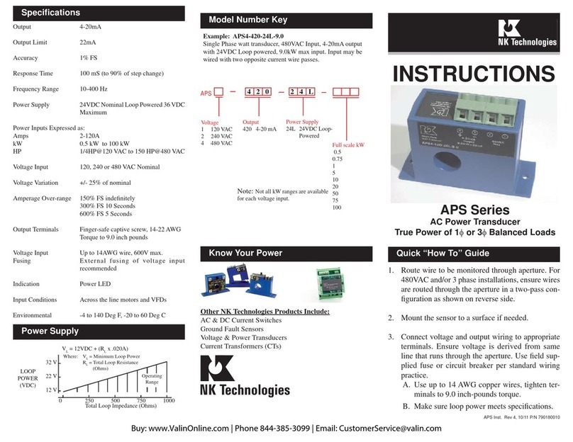
INSTRUCTIONS
1. Ensure correct sensor model was chosen for Moni-
tored Voltage of application.
2. Mount the sensor to a DIN rail using integrated
mounting clip on backside of transducer.
3. Connect monitored voltage (5) & (6) and output
wiring using 24-10AWG copper wires insulated to
75/90°. Refer to Specifications section for voltage
and impedance recommendations.
4. Connect 24VAC or DC power supply fused to 5 amp
to term. 3-4, 24-12 AWG copper. Use twisted pair
for CE compliance. Tighten all conenctions to 5-7
in/lbs torque.
Do not connect power and signal together.
VTU SERIES
AC/DC Voltage Transducers
Ranges 15, 25, 50, 60, 120, 150,
240, 300, 400, 500 and 600 Volts
4-20mA, 0-5/10VDC Outputs
VTU A - 420 - 24U - DIN
OUTPUT:
420 - 4-20mA
005 - 0-5VDC
010 - 0-10VDC
MONITORED VOLTAGE RANGE:
A - 15V
B - 25V
C - 50V
D - 60V
E - 120V
F - 150V
G - 240V
H - 300V
I - 400V
J - 500V
K - 600V
SENSOR TYPE:
VTU - AC/DC Voltage Transducers
Model Number KeySpecifications
Quick “How To” Guide
CASE STYLE:
DIN - DIN rail compatible
POWER SUPPLY:
24U - Nominal 24 VAC/DC
3511 Charter Park Drive, San Jose, CA 95136
800-959-4014 or 408-871-7510 Phone
408-871-7515 FAX
[email protected], www.nktechnologies.com VTU-DIN Instruction Sheet Rev 3 03/19 P/N 292180012
Know Your Power
Other NK Technologies Products Include:
AC & DC Current Transducers
AC & DC Current Operated Switches
1φ& 3φ Power Transducers
Current & Potential Transformers (CTs & PTs)
Power Supply 24VAC/DC External Power
(22-26VDC), <2VA
(Note: Output and power supply
negatives are not isolated).
Use class 2 power supply
Voltage Measurement 15, 25, 50, 60, 120, 150, 240, 300,
400, 500 and 600VAC or DC
Frequency Range 0 - 5KHz
Output 4–20mA (capped at 31mAmax)
0-5VDC (capped at 7.75VDC)
0-10VDC (capped at 11.5VDC)
Response Time 500 ms (to 90% value)
Accuracy < 1% Full Scale
Loading 4-20mA: < 400 ohm
0-5/10V: >50K ohm
Isolation Voltage 2500 Volts
Operating Temp. -20°C to 50°C (surrounding sensor)
Enclosure UL94V-0 Rated
Environmental -4 to 122 ° F
(-20 to 50° C),0–95% RH
Pollution Degree 2
Altitude to 2000 meters
Listings Designed to meet UL/cUL, CE
Warning! Risk of danger
Safe operation can only be guaranteed if the
transducer is used for the purpose for which it
was designed and within the limits of the techni-
cal specifications. When this symbol is used, it
means you must consult all documentation to
understand the nature of potential hazards and
the action required to avoid them.
Warning! Risk of electrical shock
When operating the transducer certain parts may
carry hazardous live voltage (e.g. primary con-
ductors, power supply). The transducer should
not be put into operation if the installation is not
complete.
For products intended for the EU market, the following is ap-
plicable to the CE compliance of the product:
The VTU series comply with EN 61010-1 CAT III 600V max
measurement category. Use 24 V input power and fuse at 5 amps.
Power source overvoltage category I as defined per EN 61010-1
Description
Installation
Output Wiring
VTU SeriesVoltageTransducersare designed tomonitorAC
or DC voltage and detect conditions where supply voltage
is above or below normal. Detecting such conditions helps
users to avoid problems commonly associated with voltage
irregularities such as motor overheating, brownouts and
conductor failure or poor connections.TheVTU is available
with 4-20mA, 0-5 or 0-10 VDC output options.
1. Transducer has no output
A. Power supply is not properly sized Check power supply
voltage and output rating. Each transducer requires less
than 2VA to operate.
B. Output polarity is not properly matched. Check and correct
wiring polarity
2. Output Signal Too Low or Too High
Transducer model improperly sized for application. Determine
the normal operating voltage of your monitored circuit and
ensure transducer selected is equal to or slightly higher than
the normal operating voltage.
3. Transducer output is always at 4mA (or zero voltage)
Primary circuit is not on. Check that the monitored circuit is
actually energized.
4. Transducer output is always at 20mA (or 5/10VDC)
Voltage is higher than transducer range. Select a higher range
product.
Troubleshooting Tips
Monitored Voltage Wiring Connection
CAUTION: TO AVOID ANY POTENTIAL FOR SHOCK
OR SAFETY HAZARD, ENSURE LINE VOLTAGE IS
DISCONNECTED AT SOURCE BEFORE WIRING TO
UNIT.
Connect input voltage to be monitored to terminals (5) and
(6) on transducerusing 24-10AWG copperwires and tighten
terminals to 5-7 inch-pounds torque.
(mA)
(% FS)
Transducer Output vs. Input Voltage
0.0 100.0
50.0
Input Voltage
VTU Series
+
AC/DC Voltage (primary)
(5) (6)
+-
Load
(PLC, meter,etc.)
24 VAC/DC
Power Supply
(1) (2) (3) (4)
Do not connect the power supply and signal together.
There is no isolation between power and signal.
Use twisted pair for power supply conductors for full com-
pliance with CE directives.
Note: Voltage output will be linear in the same manner, with
zero at zero primary voltage and 5 or 10 VDC at the full range
measured voltage.
Connect control or monitoring wires to the sensor terminals
1 and 2. Use up to 24-12AWG copper wire insulated to
75/90°C and tighten terminals to5-7 inch-pounds torque.
Observe polarity, terminal 1 is the positive output, 2 is nega-
tive.
5/10VDC
0 VDC
Current Output
Voltage Output
VTU transducers feature a 35mm wide DIN rail compatible
enclosure and are typically located in the same environ-
ment as motors, contactors, heaters, pull-boxes, and other
electrical enclosures.
To mount on DIN rail: Orient transducer so that line volt-
age terminals 5 and 6 are upright/on top of unit and snap
securely onto DIN rail. To remove, insert small screwdriver
into the lower mounting hole of the spring loaded clip, and
push the handle end of the screwdriver toward the sensor
base to release the tension on the rail.
Push in to release clip
To mount using screws: Insert screws and mount to back
plane or other suitably flat surface.
VTU-DIN Instruction Sheet Rev 3 03/19 P/N 292180012

Other NK TECHNOLOGIES Transducer manuals

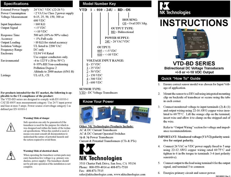
NK TECHNOLOGIES APS Series User manual

NK TECHNOLOGIES

NK TECHNOLOGIES APS Series User manual

NK TECHNOLOGIES AT-TH Series User manual

NK TECHNOLOGIES

NK TECHNOLOGIES AT-TH Series User manual

NK TECHNOLOGIES DT Series User manual

NK TECHNOLOGIES

NK TECHNOLOGIES DT Series User manual

NK TECHNOLOGIES DT Series User manual

NK TECHNOLOGIES

NK TECHNOLOGIES DT Series User manual

NK TECHNOLOGIES AT SERIES User manual

NK TECHNOLOGIES

NK TECHNOLOGIES AT SERIES User manual

NK TECHNOLOGIES VTU Series User manual

NK TECHNOLOGIES

NK TECHNOLOGIES VTU Series User manual

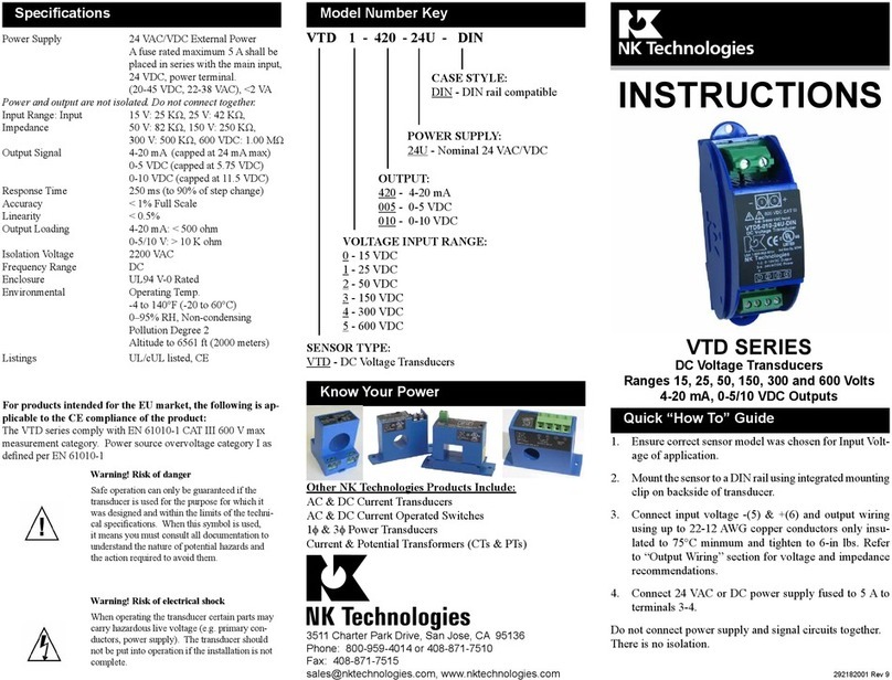
NK TECHNOLOGIES VTD Series User manual

NK TECHNOLOGIES

NK TECHNOLOGIES VTD Series User manual

NK TECHNOLOGIES AT 2 Series User manual

NK TECHNOLOGIES

NK TECHNOLOGIES AT 2 Series User manual

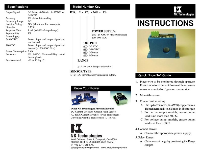
NK TECHNOLOGIES DTC 2-420-24U-FL User manual

NK TECHNOLOGIES

NK TECHNOLOGIES DTC 2-420-24U-FL User manual

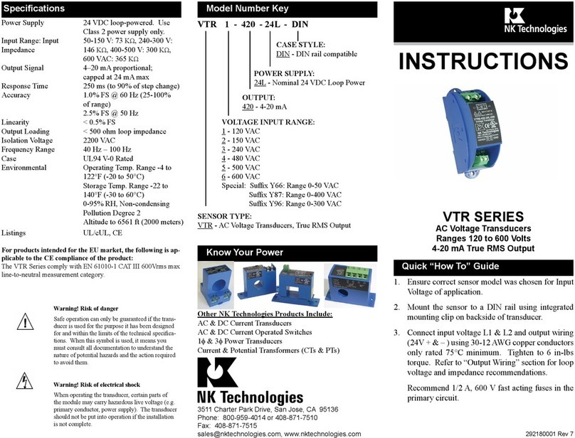
NK TECHNOLOGIES VTR Series User manual

NK TECHNOLOGIES

NK TECHNOLOGIES VTR Series User manual

NK TECHNOLOGIES APS Series User manual

NK TECHNOLOGIES

NK TECHNOLOGIES APS Series User manual

NK TECHNOLOGIES VTD-BD Series User manual

NK TECHNOLOGIES

NK TECHNOLOGIES VTD-BD Series User manual

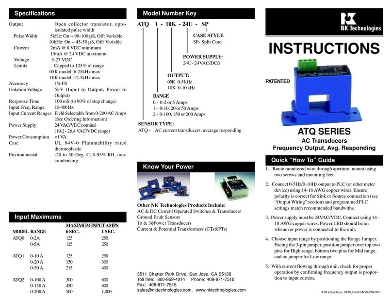
NK TECHNOLOGIES ATQ Series User manual

NK TECHNOLOGIES

NK TECHNOLOGIES ATQ Series User manual

Popular Transducer manuals by other brands

Setra Systems 550 installation guide

Setra Systems

Setra Systems 550 installation guide

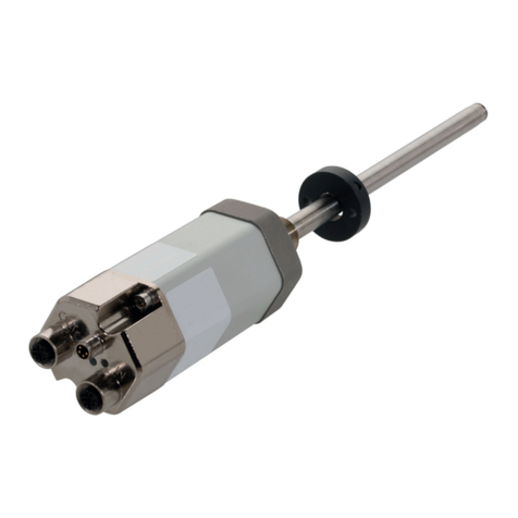
Balluff BTL7-V50D-M P-C003 Series user guide

Balluff

Balluff BTL7-V50D-M P-C003 Series user guide

Humminbird 531392-1 B installation manual

Humminbird

Humminbird 531392-1 B installation manual

TSI Incorporated 8455 Operation and service manual

TSI Incorporated

TSI Incorporated 8455 Operation and service manual

Balluff BTL7-S5 B-M Series user guide

Balluff

Balluff BTL7-S5 B-M Series user guide

Furuno 82B-35R Operator's manual

Furuno

Furuno 82B-35R Operator's manual

HBM S2 Mounting instructions

HBM

HBM S2 Mounting instructions

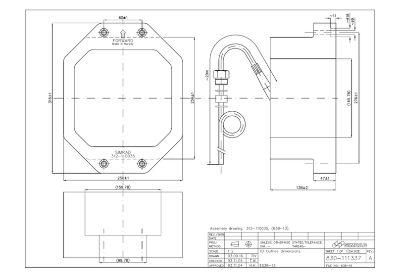
Simrad ES38-12 -  REV C Dimensions

Simrad

Simrad ES38-12 - REV C Dimensions

SOLIDDRIVE SD1 Installation & use guide

SOLIDDRIVE

SOLIDDRIVE SD1 Installation & use guide

Seli SMU-XX manual

Seli

Seli SMU-XX manual

Balluff BTL7-A50 Series user guide

Balluff

Balluff BTL7-A50 Series user guide

S+S Regeltechnik PREMASGARD 114 Series Operating Instructions, Mounting & Installation

S+S Regeltechnik

S+S Regeltechnik PREMASGARD 114 Series Operating Instructions, Mounting & Installation

Shinkawa FK F Series instruction manual

Shinkawa

Shinkawa FK F Series instruction manual

Pulsar dBi Series instruction manual

Pulsar

Pulsar dBi Series instruction manual

HBM U5 Series Mounting instructions

HBM

HBM U5 Series Mounting instructions

Siemens 7KG6000-8AA operating instructions

Siemens

Siemens 7KG6000-8AA operating instructions

Omega PX276 instruction sheet

Omega

Omega PX276 instruction sheet

JBL Professional Series Technical manual

JBL

JBL Professional Series Technical manual

manuals.online logo
manuals.online logoBrands
  • About & Mission
  • Contact us
  • Privacy Policy
  • Terms and Conditions

Copyright 2025 Manuals.Online. All Rights Reserved.