SIAP+MICROS t055 TPIR Guide
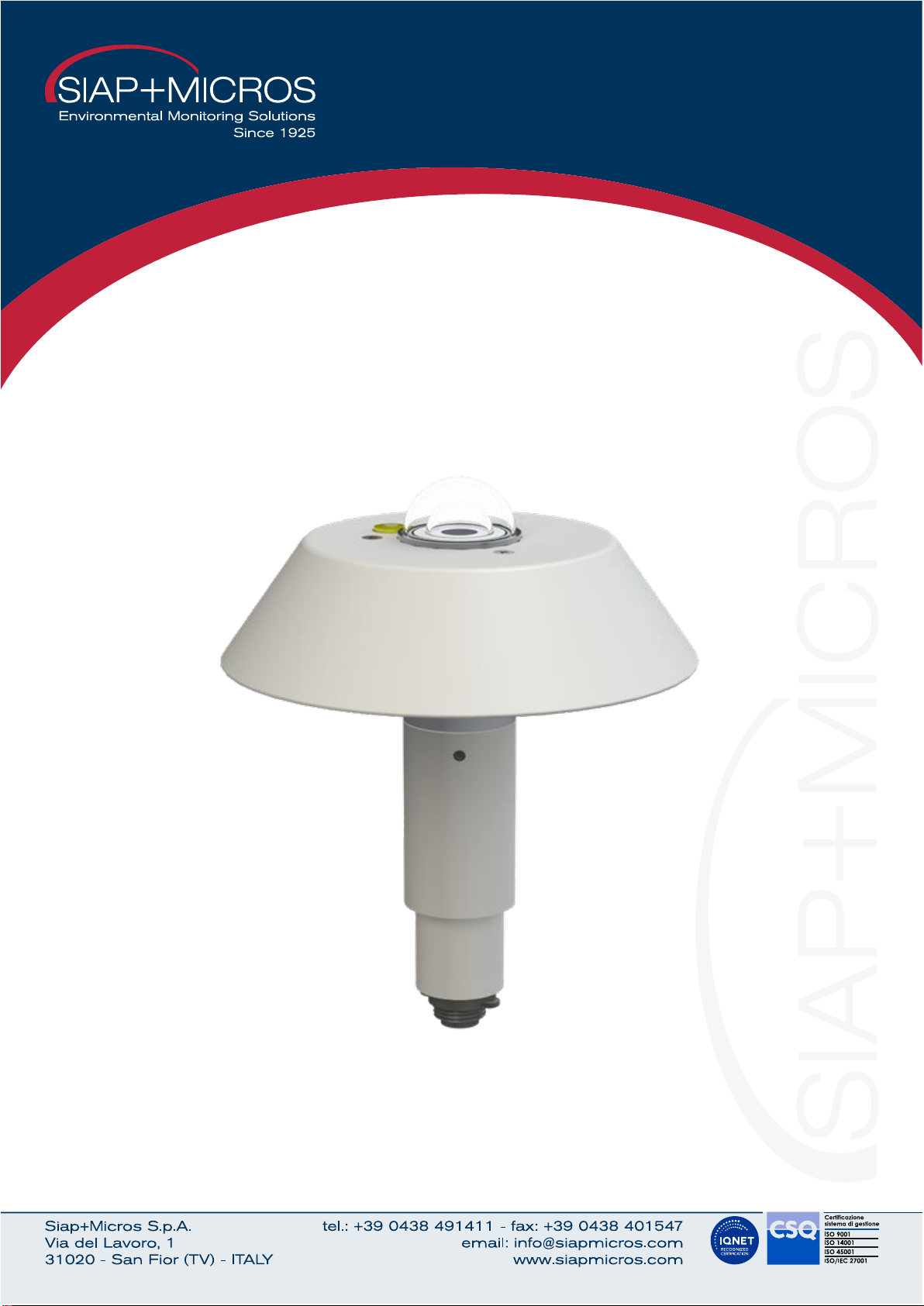
t055 TPIR
Global Solar Radiation Transducer
User Manual and maintenance

User manual and maintenance
t055-di TPIR.docx
27/10/2023 2Vers.: 1.0
Summary
1Introduction ................................................................................................................................................ 3
2Technical specificaion ................................................................................................................................ 4
2.1 Operation scheme ............................................................................................................................. 5
3Installation and maintenance ..................................................................................................................... 6
3.1 Installation.......................................................................................................................................... 6
3.2 Maintanance ...................................................................................................................................... 6
4Electrical connection.................................................................................................................................. 7
4.1 Connector output ............................................................................................................................... 7
4.2 Connection cable ............................................................................................................................... 7
4.3 Data readinding in serial (RS485 Modbus and SDI-12) .................................................................... 7
4.3.1 RS485 Modbus mode .................................................................................................................... 7
4.3.2 SDI-12 mode.................................................................................................................................. 8
5Generic information ................................................................................................................................... 9
5.1 Safety................................................................................................................................................. 9
5.2 Appropriate use of the equipment ................................................................................................... 10
5.3 Storage ............................................................................................................................................ 10
5.4 Moving ............................................................................................................................................. 10
5.5 Disposal information ........................................................................................................................ 10
6Revision history ........................................................................................................................................11

User manual and maintenance
t055-di TPIR.docx
27/10/2023 3Vers.: 1.0
1Introduction
TPIR measures the global solar radiation, calculated as sum of the direct sun radiation, and the radiation
diffused by the sky and scattered clouds. Thanks to its standards of accuracy the sensor is a very suitable
device for various applications in the field of meteorology. TPIR is equipped with a thermopile element,
specifically designed and developed for SIAP + MICROS. The sensing element generates a tension
proportional to the captured radiation, which is acquired by a signal conditioning electronics that normalizes
the output in a standard tension, current, Modbus or SDI-12 signal. Performance features are significantly
improved thanks to a double dome made of special optical glass (Schott K5), which allows a wide range of
solar radiation frequency measurement (0.3 ÷ 3 μm). The production process is fulfilled by a calibration in a
climatic chamber with an artificial light source, in order to obtain high accuracy even when the temperature
varies. The sensor is supplied with power and signal cable (4m).
Ordering Codes:
Current, tension, RS485 Modbus serial Output:........................................t055d TPIR-IVS
SDI-12 serial output: ..................................................................................t055i TPIR-12
User manual and maintenance
t055-di TPIR.docx
27/10/2023 4Vers.: 1.0
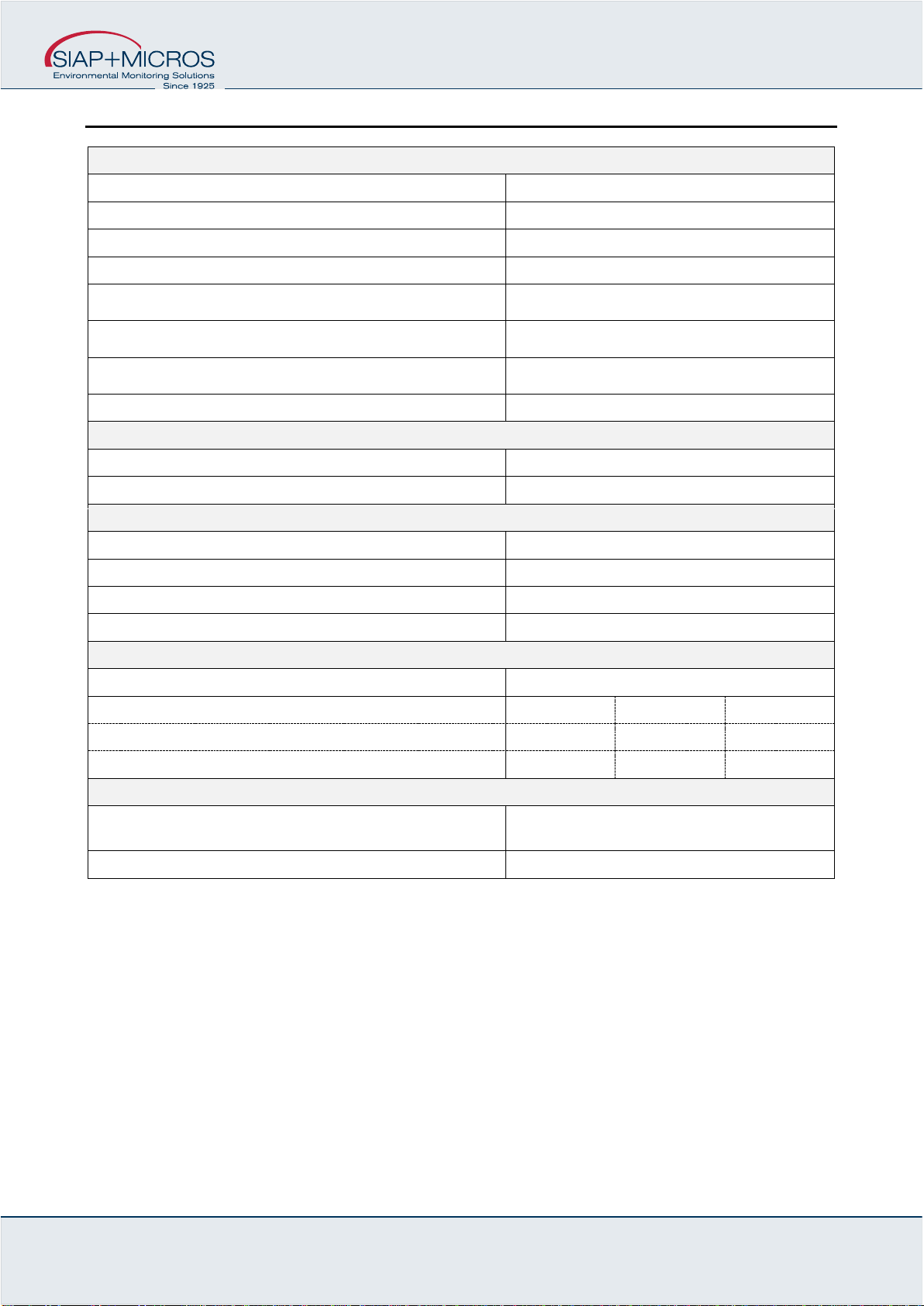
2Technical specificaion
Measurement performance
Transducer
Thermopile
Measurement range
0 ÷ 1300 W/m2
Accuracy
± 10 W/m2
Resolution
1 W/m2
Directional response
< ± 20 W/m2
Non linearity
± 1 %
Spectral range
0.3 ÷ 3 μm
Inclination response
± 2 %
Operating conditions
Temperature
-30 ÷ 60 °C
Humidity
0 ÷ 100 RH%
Outputs
Current
4 ÷ 20 mA ↔-30 ÷ 60 °C
Tension
0 ÷ 2 V ↔-30 ÷ 60 °C
RS485 MODBUS
Temperature
SDI-12
Temperature
Power supply and Consumption
Supply voltage (non-natural output versions)
7 ÷ 30 Vdc
Voltage supply
Min
Typical
Max
Power consumption
5
25
4 ÷ 20 mA
1
3
0 ÷2 V / RS485 MODBUS / SDI-12
Mechanical specifications
Plastic material, aluminium alloy, brass,
stainless steel screws
Protective body
IP67 / 7 pole male connector

User manual and maintenance
t055-di TPIR.docx
27/10/2023 5Vers.: 1.0
Dimension:
H – maximum height: 250 mm
D1 – maximum diameter: 210 mm
D2 – fixing diameter: 40 mm
Element:
A – glass domes
B – fixing shank
C – cover plate
D – thermopile
E - level
Weight: 1,1 kg
2.1 Operation scheme

User manual and maintenance
t055-di TPIR.docx
27/10/2023 6Vers.: 1.0
3Installation and maintenance
3.1 Installation
The sensor must be installed on
special brackets which distance it
sufficiently from reflected heat sources
(for example the same support pole of
the station) which could influence its
correct measurement.
For correct installation, the sensor
should be placed at a distance from
the closest obstacle (pylons, trees,
buildings) equal to 10 times the height
of the obstacle itself, this to minimize
the effects of alteration of the normal air flow.
The TPIR transducer is normally positioned (according to WMO standards) at a height of about 2 meters from
the ground level. Normally, in Siap+Micros meteorological stations, it is installed with special brackets (see
drawing) present on the poles. On these brackets the sensor must be installed with special muffler collars fixed
to the stem of the sensor itself (part with ø40mm).
It is important that the transducer is installed so that no obstacle can generate a darkened area from the sun
(shadow) making correct measurement impossible. In order not even the pole of the monitoring station can
generate this shadow, the transducer must be positioned in the "direction of the sun". For this reason, the TPIR
must be placed in a SOUTH direction if it is installed in the NORTHERN hemisphere, vice versa in the NORTH
direction if it is installed in the SOUTH hemisphere.
3.2 Maintanance
In cases of heavy dirt due to atmospheric pollutants, dust, etc., the glass dome placed on top of the TPIR
transducer must be kept clean with the use of non-abrasive materials and non-corrosive detergents.
Furthermore, the dehumidification salts must be checked periodically. In a "normal" situation, the salts are light
blue/blue, otherwise they become white/pink and must be replaced to guarantee a good response from the
instrument.
User manual and maintenance
t055-di TPIR.docx
27/10/2023 7Vers.: 1.0
4Electrical connection
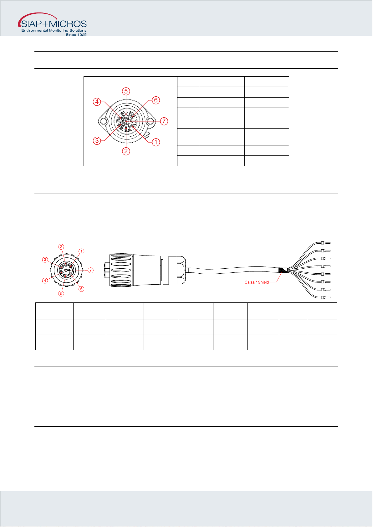
4.1 Connector output
Pin
TPIR-IVS
TPIR-12
1
A-RS485
A-RS485
2
B-RS485
B-RS485
3
+0÷2 Vdc
SDI-12 (data)
4
+4÷20 mA
+4÷20 mA
5
-0÷2 Vdc
-0÷20 mA
-4÷20 mA
6
Vcc
SDI-12 (Vcc)
7
GND
GND
4.2 Connection cable
The connection cable supplied with the sensor is made with circular connectors with housing, 8x0.22 mm2
shielded cable and ferrules for connection to the data logger terminals. The sock is connected to the black
cable.
Pin
1
2
3
4
5
6
7
7
Cable
Red
White
Green
Black
Orange
Yellow
Blue
Brown
TPIR-IVS
A-RS485
B-RS485
+0÷2 Vdc
+4÷20 mA
-0÷2 Vdc
-4÷20 mA
Vcc
GND
GND
TPIR-12
A-RS485
B-RS485
SDI-12
(data)
+4÷20 mA
-4÷20 mA
SDI-12
(Vcc)
GND
GND
4.3 Data readinding in serial (RS485 Modbus and SDI-12)
Sensors with RS485 Modbus or SDI-12 output send data only upon specific request from the PC, data logger
or PLC.
Below are the correct communication parameters of the device performing the interrogation.
4.3.1 RS485 Modbus mode
Serial port settings: 9600 baud, no parity, 8 data bit, 1 bit di stop
Compatible with ModBus RTU protocol, functions supported: “03 – read Holding Registers” e “04 – Read Input
Registers”.
User manual and maintenance
t055-di TPIR.docx
27/10/2023 8Vers.: 1.0
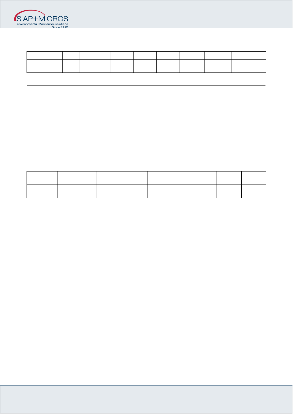
Data type: “2 registers swapped float IEEE 754 in the form CDAB where A is the most significant byte of the
float and D is the less significant byte of the float (swapped float)”.
ID
Registers
Units
Reg. 1-2
Reg. 3-4
Reg. 5-6
Reg. 7-8
Reg. 9-10
Reg. 11-12
Reg. 13-14
7
7
Wm2
-
-
-
Solar
Radiation
-
Diagnostic
Supply Voltage
4.3.2 SDI-12 mode
Serial port settings: 1200 baud, even parity, 7 data bit, 1 bit di stop
Supported commands (a = 3, sensor address)
?! Address Query
aI! Send Identification
aM! Start Measurement
aC! Start Concurrent Measurement
aD0! Send Data
a
Position
Units
Decimals
Position 1
Position 2
Position
3
Position 4
Position 5
Position 6
Position
7
7
1
Wm2
1
Solar
Radiation
Diagnostic
Supply
Voltage
-
-
-
-

User manual and maintenance
t055-di TPIR.docx
27/10/2023 9Vers.: 1.0
5Generic information
The qualitative level of our instruments is the result of a continuous evolution of the product. This may cause
differences between what is reported in the manual and the instrument you have purchased.
Siap+Micros S.p.A. reserves the right to modify without notice technical specifications and dimensions to adapt
them to the needs of the product.
5.1 Safety
Please read these safety instructions carefully before using this product:
•The warranty will be void if the product is used differently from the instructions described in this manual.
•Any sign of tampering will void the warranty
•Use the devices only according to the instructions (environmental management, operation, wiring,
installation, etc.) provided in this manual
•The correct and safe operation of the device can only be guaranteed if the transport, storage, operation
and management of the device are compliant. This also applies to product maintenance.
•The device shall not be exposed to aggressive chemicals or solvents that could damage the plastic
casing and/or corrode the metal parts.
•Maintenance should only be performed by qualified and well trained personnel.
It is appropriate to carry out a careful risk assessment in relation to the context of installation and use of the
device by the installer considering the possible meteorological station in its complexity without being limited to
the sensor.
The instruments must be installed according to the rules of the trade, with equipment that complies with
applicable regulations and using supports correctly sized by qualified technicians and designed for the specific
purpose.
During installation operations, check the suitability of the surrounding environment and compliance with local
safety regulations.
The manufacturer declines all responsibility in case of failure due to negligence of the instructions, tampering,
uses not described in this manual, improper use, use by operators not trained.
Read the instructions and intended use carefully and be sure you understand before installing the device
Before starting the activities, check the integrity of the instrument to be installed, prepare the equipment
necessary for the work and wear the necessary PPE.
Take adequate measures to prevent the access of foreign personnel (untrained and uninformed) during the
installation, maintenance or replacement of the instrument.
Take precautions to avoid falling objects, both during the installation phases and during the operation of the
instrument.
Do not perform any activity in bad weather conditions.

User manual and maintenance
t055-di TPIR.docx
27/10/2023 10 Vers.: 1.0
During maintenance, particularly if the station is not frequented, visually check for the absence of dangerous
insects and, if not, use suitable insecticides.
Consider the presence of any animals near the station, if so, pay attention to them.
Use only SIAP+MICROS original spare parts
The instrument is not classified suitable (according to Directive 2014/34/EU) for use in atmospheres with
potential explosion risk pursuant to Directive 99/92/EC.
SIAP+MICROS strives to minimize health and safety risks in all phases of the instrument's life, including
installation, use, maintenance, decommissioning and disposal.
5.2 Appropriate use of the equipment
Use the instrument for its intended purpose, do not use it for any other purpose or cause malfunctions and/or
damage.
5.3 Storage
If you do not plan to use the equipment for an extended period of time (at least one year) disconnect all cables
from the equipment, place it in a clear plastic bag along with a bag of desiccant salts and seal the bag with
tape. Put appropriate indication on the bag of the contents and weight of the equipment by inserting the wording
"HANDLE WITH CARE".
Store the instrument in an environment with a temperature between 0°C and 60°C with a humidity not
exceeding 80%. Make sure that the instrument is stored in a stable position and that it cannot be damaged or
moved by inexperience or carelessness. Do not stack other tools or weights. Do not place the instrument on
top of other instruments and in any case ensure the solidity and stability of the underlying support.
Non esporre, stoccare lo strumento in ambienti con presenza di vapori e/o gas corrosivi.
5.4 Moving
In order to avoid any damage to the device during transportation, please keep it in upright position without
shaking.
5.5 Disposal information
Electrical and electronic equipment marked with specific symbol in compliance with 2012/19/EU
Directive must be disposed of separately from household waste. European users can hand them
over to the dealer or to the manufacturer when purchasing a new electrical and electronic
equipment, or to a WEEE collection point designated by local authorities. Illegal disposal is
punished by law.
Disposing of electrical and electronic equipment separately from normal waste helps to preserve natural
resources and allows materials to be recycled in an environmentally friendly way without risks to human health.
User manual and maintenance
t055-di TPIR.docx
27/10/2023 11 Vers.: 1.0
6Revision history
The following table shows the description of the changes made to this document.
Version
Date
Updates
1.0
05/06/2023
Current version of the document.
All the information content in this document are the current available at the printing phase. Siap+Micros S.p.A. reserve the rights to change
the specifications without any advance notice
This manual suits for next models
2
Table of contents
Other SIAP+MICROS Transducer manuals

SIAP+MICROS
SIAP+MICROS t012 TTS Guide

SIAP+MICROS
SIAP+MICROS t018 TTP Guide

SIAP+MICROS
SIAP+MICROS t031 TVV Guide

SIAP+MICROS
SIAP+MICROS t003 TRH Guide

SIAP+MICROS
SIAP+MICROS t002 TTT Guide

SIAP+MICROS
SIAP+MICROS t020 TTA Guide

SIAP+MICROS
SIAP+MICROS t033 TDV Guide

SIAP+MICROS
SIAP+MICROS t001 TTEP Guide

SIAP+MICROS
SIAP+MICROS t018 TTP Guide

SIAP+MICROS
SIAP+MICROS t031 TVV Guide


