Barnant Company 877-9605 User manual
OPERATING MANUAL
LIQUID-SENSOR CONTROLLERS
MODEL NO. 877-9600
MODEL NO. 877-9605
AND
LIQUID-PAD DETECTORS
MODEL NO. 877-9500
MODEL NO. 877-9501
Barnant Company
28W092 Commercial Ave.
Barrington, Illinois U.S.A. 60010-2392
(847) 381-7050
(847) 381-7053 (Fax)
800-637-3739
www.barnant.com
A-1299-0578
Edition 03

SAFETY PRECAUTIONS
WARNINGS:If the equipmentisusedinamannerotherthanasspeci-
fied, protection provided by the equipment may be
impaired.
No user serviceable parts are inside of this Controller.
Refer servicing to your dealer.
WARNING:The LIQUID SENSOR Controller must be positioned so
leaking liquid will not enter the rear power connectors.
Use of a power line with a Ground Fault Interrupt (GFI) is
recommended.
CAUTION:Use with caustic liquids not compatible with detector
materials voids warranty.
i
EU Declaration of Conformity
Name of Apparatus:Liquid-Sensor Controller
Model Number:877-9605
Description of Apparatus:Fluid Monitor System
Barnant Company declares that the above model is in conformity to the following
harmonized standards and directives:
Applicable
DirectivesApplicable
SpecificationsManufacturer’s
Report Number
73/23/EEC
93/68/EECEN61010-1/A2: 1995TR9516
89/336/EEC
92/31/EEC
93/68/EEC
EN61326-1/A1: 1998TR9519
The last two digits of the year in which the current configuration of the above models
was assessed per the Low Voltage Directive is: 00.
Manufacturer:
Barnant Company Division
Cole-Parmer Instrument Company
28W092 Commercial Avenue
Barrington, IL 60010
USA
Tel.: 847-381-7050
Manufacturer’s Signature:
22 August, 2000
________________________________________________
James W. DollDate
Vice President, Engineering

TABLE OF CONTENTS
TitlePage
SAFETY PRECAUTIONS.....................................i
INTRODUCTION...........................................2
APPLICATIONS............................................3
DESCRIPTION.............................................6
INSTALLATION AND SETUP..................................9
OPERATION.............................................13
Operator Control and Indicators.............................13
Startup Procedure.......................................15
Operational Checks......................................15
SENSITIVITY ADJUSTMENT................................16
MAINTENANCE AND TROUBLESHOOTING....................17
Fuse Replacement.......................................17
Cleaning ...............................................17
Troubleshooting.........................................18
ACCESSORIES...........................................19
SPECIFICATIONS.........................................20
WARRANTY..............................................21
PRODUCT RETURN.......................................21
TECHNICAL ASSISTANCE..................................21
APPENDIX A: AUXILIARY CABLE CONNECTIONS.............22
Only the Model 877-9600 Liquid-Sensor Controller is UL and cUL listed.
1
Trademarks bearing the ® symbol in this publication are registered in the U.S. and in other countries.

INTRODUCTION
The LIQUID-SENSOR Controller is a two-channel alarm system used to
sense liquid leaks using a specially designed detector or used with other
liquid detectors such as high or low liquid level detectors. The Model
877-9600 LIQUID-SENSOR Controller operates from 115V ACand the
Model877-9605operatesfrom230VAC.Whenanalarmconditionissensed
oneitherchannel,theLIQUID-SENSORControllercanperformthefollowing
actions:
•Disconnect power to a pump drive.
•Activate an auxiliary pump drive to resume pumping through a second
pump drive.
•Activate the front panel red ALARM ON indicator.
•Sound an audible alarm if the audible alarm is enabled.
•Provide a contact closure output that can be used to activate an
Environment Monitor for automatically telephoning the user of the failure,
or to activate any other device that operates from a contact closure
input. The contact closure may also be used to operate shut-off or
switchable valves to redirect flow.
The LIQUID-PAD Detector Model 877-9500 (detector with cable) or Model
877-9501 (detector without cable) is used to sense leaks in pump heads
resultingfromrupturesofthetubing.Thisdetectorisnotsuppliedwiththeunit
and must be ordered separately. (See ACCESSORIES.)
2

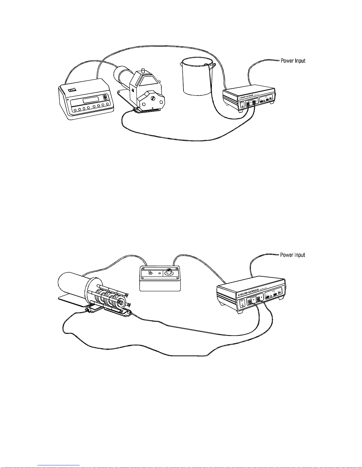
APPLICATIONS
The LIQUID-SENSOR Controller and LIQUID-PAD Detector can be used
with a wide variety of different pump systems for leak detection. The alarm
controller has two inputs. These can both be used with LIQUID-PAD
Detectors, or one input can be used with a LIQUID-PAD Detector and the
secondinputusedwithothertypedetectorssuchasaliquidleveldetectorfor
determining high or low levels in a container. Figures 1 through 5 show
varioussuggested detectorarrangements indifferent pumpsystems. Tubing
is omitted for clarity.
3
Figure 1. Typical B/T ®RAPID-LOAD ®Pump with LIQUID-PAD Detector
positioned under open side of pump

4
Figure 2. Typical L/S ®Cartridge Pump with two LIQUID-PAD Detectors
centered under the group of cartridges
Figure 3. Typical L/S EASY-LOAD ®Pump with LIQUID-PAD Detector
positioned under main pump, auxiliary pump mounted on top
of main pump and both pumps connected to Alarm Controller
for automatic switch over when a leak is detected
5
Figure 4. Typical I/P ®EASY-LOAD Pump with LIQUID-PAD Detector
centered under the pump and a level detector connected to the
second input of the Alarm Controller
Figure 5. Standard Stacked Pump System with two LIQUID-PAD
Detectors positioned for optimum leak detection
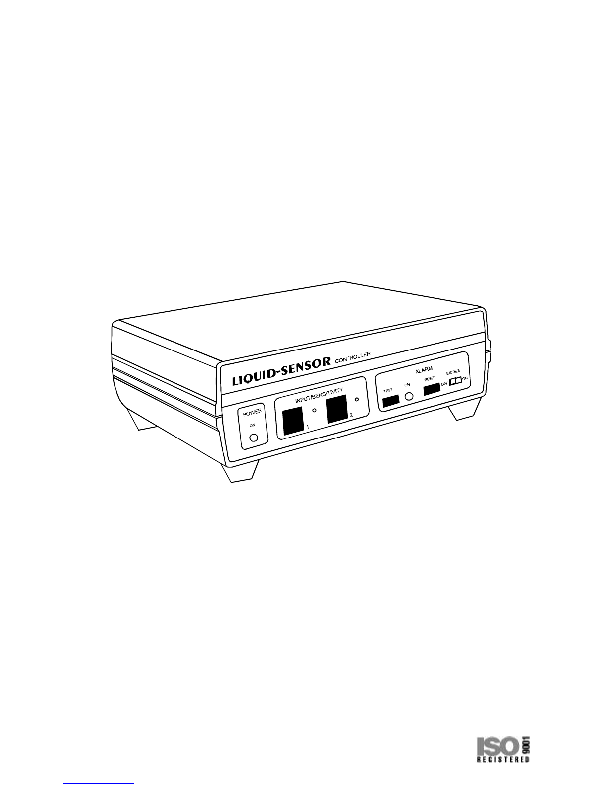
DESCRIPTION
The LIQUID-SENSOR Controller, shown in Figure 6, is used to monitor
various liquid detector devices. When an alarm condition is detected, the
controller deactivates the rear panel MAIN OUTPUT power connector and
suppliespowertotheAUXILIARYOUTPUTpowerconnector.Also,whenthe
alarm condition is detected, a contact closure output is provided at the rear
panel CONTACT CLOSURE OUTPUT connector (a 1/8-inch phone-type
connector) for activating remote devices such as an Environment Monitor or
a second pump drive. The fault condition is indicated by a red ALARM ON
indicator on the front panel and by an audible alarm (unless the ALARM
AUDIBLE switch has been set to OFF).
TheMAINandAUXILIARYconnectors,showninFigures7and8,areusedto
connect to external devices such as pumps. The pump connected to the
MAINOUTPUTconnectorwilloperatewhennoalarmconditionexists.When
an alarm condition is detected, power to the MAIN OUTPUT connector is
turnedoffandpowerisappliedtotheAUXILIARYOUTPUTconnector.Thus,
ifnopumpisconnectedtotheAUXILIARYOUTPUTconnector,pumpingwill
cease. If a pump is connected to the AUXILIARY OUTPUT connector, that
pump will be turned on. The switch over occurs within one second after
detection of an alarm condition.
6
Figure 6. LIQUID-SENSOR Controller (Alarm Module)
Power is applied to the unit through a permanently attached line cord on the
115V AC model and through an IEC 320/CEE 22 connector coupler (female
line cord/male socket) on the 230V AC units. A number of accessory input
and output power cords are available. (See ACCESSORIES.) The power is
controlled by the rear panel OFF-ON switch. Power-on is indicated by a front
panel green POWER ON indicator.
The CONTACT CLOSURE OUTPUT connector (rear panel) provides a
latched contact closure output, rated 30V DC at 1 ampere max., when an
alarmconditionisdetected.ThisoutputcanbeconnectedtoanEnvironment
Monitor,whichthencantelephonetheusertosignalthealarmcondition.This
output can also be connected to any device that operates from a contact
closure condition, such as a warning system. An accessory cable is listed in
the ACCESSORIES Section.
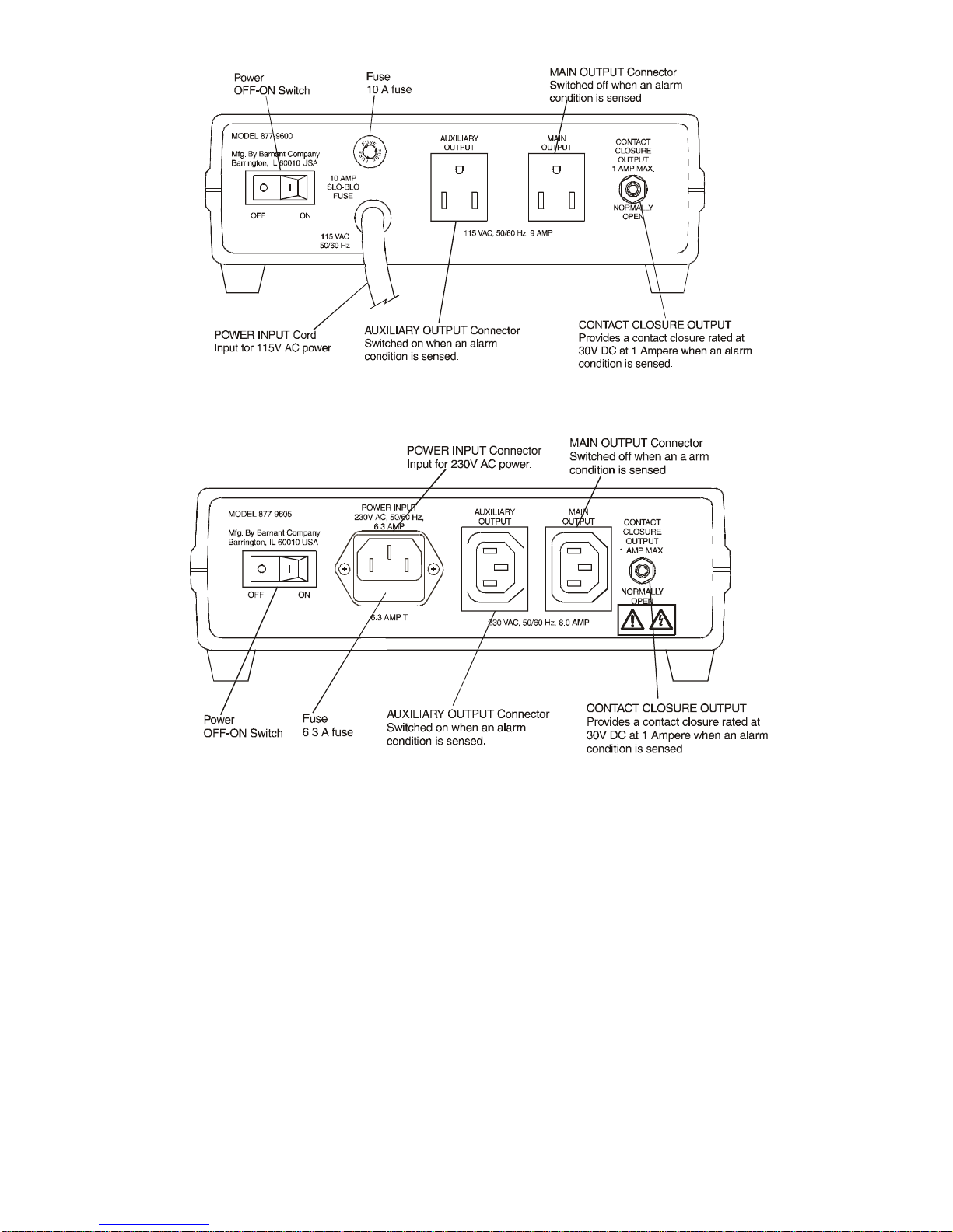
7
Figure 7. Rear Panel Model 877-9600 (115V AC)
Figure 8. Rear Panel Model 877-9605 (230V AC)
The locking modular INPUT connectors (front panel) connect to external
detectors. Each input has a SENSITIVITY adjustment that is used only with
the LIQUID-PAD Detectors. The sensitivity is factory set so that when the
detector is placed within one inch of the pump, less than one mL of
water-based liquid will trigger the detector. For other types of liquids, or to
change the sensitivity level, refer to the SENSITIVITY ADJUSTMENT
Section. Sensitivity adjustment may be required when operating with cables
longer than 3-1/2 feet or in a high-temperature, high-humidity environment.
The LIQUID-SENSOR Controller is housed in a slate gray ABS plastic
enclosure, with aluminum front and rear panels. The unit can be placed on a
flat surface, on a support platform or on the top surface of some
MASTERFLEX ®or other type pumps.
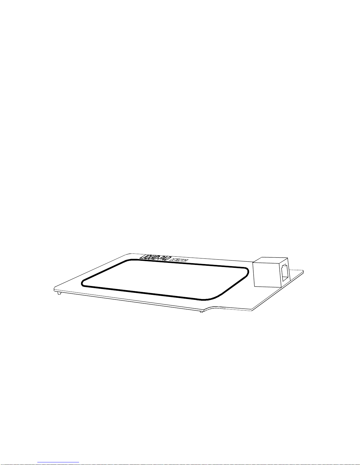
The LIQUID-PAD Detector Model 877-9500 (with cable) or Model 877-9501
(without cable), Figure 9, operates on a capacitance change principle. The
detector is designed to be placed under the pump. If a leak occurs in the
pump tubing, the liquid will fall on the top surface of the detector. When
sufficient surface area is moistened (less than 1 mL of water-based liquid
when using the factory sensitivity setting), the change in capacitance is
sufficient to activate the alarm circuits. The detector has a locking modular
type connector. The cable between the detector and the controller is 3-1/2
feet long with modular locking connectors on both ends. Ten-foot and
fifteen-foot accessory cables are available. Refer to APPENDIX A for pin
configuration for the cables when connecting other detector types.
A four-inch hook-and-loop fabric fastener strip allows for attachment of the
detector pad to a flat surface to prevent the detector pad from moving. The
detector pad can also be permanently mounted by attaching it to a flat
surfacewithtwo#4screws.Thescrewlocationsatthecornersofthedetector
padare indicated bytwocircular markers.Thedetector structurewillneedto
be punctured by the screw for permanent attachment.
8
Figure 9. LIQUID-PAD Detector Model 877-9501

INSTALLATION AND SETUP
NOTE:Retainallpackingmaterialsuntilproperoperationhasbeenverified.
WARNING:The LIQUID-SENSOR Controller must be positioned so
leakingliquidwillnot enter the rear power connectors.Use
ofapowerlinewithaGroundFaultInterrupt(GFI)isrecom-
mended.
Proceed as follows to setup the LIQUID-SENSOR Controller:
1. Place the rear panel power OFF-ON switch in the OFF position.
NOTE:For 115V AC pump models, the pump power cord will plug directly
into the MAIN OUTPUT or AUXILIARY OUTPUT connectors on the
rearpanel of theLIQUID-SENSORController. For230VACmodels,
use pump cable 77096-50 for pumps with European connectors or
pump cable 77096-55 for pumps with other style connectors.
2. Connect pumps as follows:
a.If a main pump and a standby (auxiliary) pump are to be used,
connectthemainpumptotheMAINOUTPUTconnector on therear
panel and connect the standby (auxiliary pump) to the AUXILIARY
OUTPUT connector.
b.Ifonly themainpump istobe usedwithno standby,andthe pumpis
to shut down when an alarm condition exists, connect the main
pump to the MAIN OUTPUT connector. The AUXILIARY OUTPUT
connectorcanbeusedtopowerotherdevicessuchaslights,remote
alarms or other equipment.
c.Ifonly themainpump istobe usedwithno standby,andthe pumpis
not to shut down when an alarm condition exists, connect the main
pump to a separate power source. The MAIN OUTPUT connector
andtheAUXILIARYOUTPUTconnectorcanbeusedtopowerother
devices such as lights, remote alarms or other equipment.
3. Connect one end of the detector cable(s) to the front panel INPUT
connector(s) and the other end to the desired detector(s). Only one
detectorcanbeconnectedtoeachINPUTconnector.Detectorsmustbe
connected using a cable configured as shown in APPENDIX A. Make
sure cable connections are secure or unit will not function
properly .
4. The LIQUID-PAD Detector must be positioned under the pump so that
any leakage will drip onto the detector pad target area (area outlined
with the black lines). The detector can be secured in place using
hook-and-loop fabric fasteners or can be permanently fastened with #4
screws.Twocircularmarksarelocatedontheouteredgeofthe detector
9

for position of screws. Do not insert screws in any other location on the
detectorpads.Thelocationofthedetectorforvarioustypicalpumpsare
as follows:
a.For a typical B/T RAPID-FLOW pump, the detector should be
located directly under the opening at the right side of the pump as
shown in Figure 10.
b.For typical L/S Cartridge pumps, the detector should be centered
under the group of cartridges. For large numbers of cartridges, use
two detectors as shown in Figure 11.
10
Figure 11. Positioning LIQUID-PAD Detectors
under an L/S Cartridge Pump
Figure 10. Positioning a LIQUID-PAD Detector
under a B/T RAPID-FLOW Pump
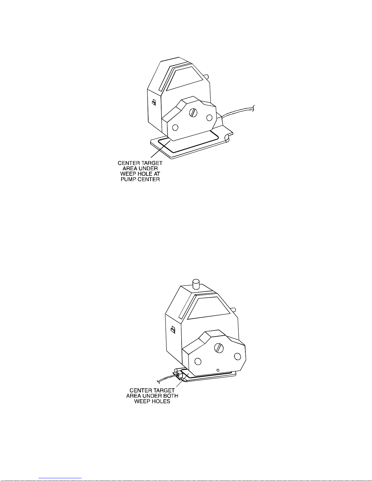
c.FortypicalL/SEASY-LOADpumps,thedetectorshouldbecentered
directly under the weep hole as shown in Figure 12.
d.For typical I/P EASY-LOAD pumps, two weep holes are located
under the pump. A single detector can be centered under the weep
holes as shown in Figure 13. For better reliability, two separate
detectors can be used with one centered under each weep hole as
shown in Figure 14.
11
Figure 12. Positioning a LIQUID-PAD Detector under an
L/S EASY-LOAD Pump
Figure 13. Positioning a single LIQUID-PAD Detector under an
I/P EASY-LOAD Pump
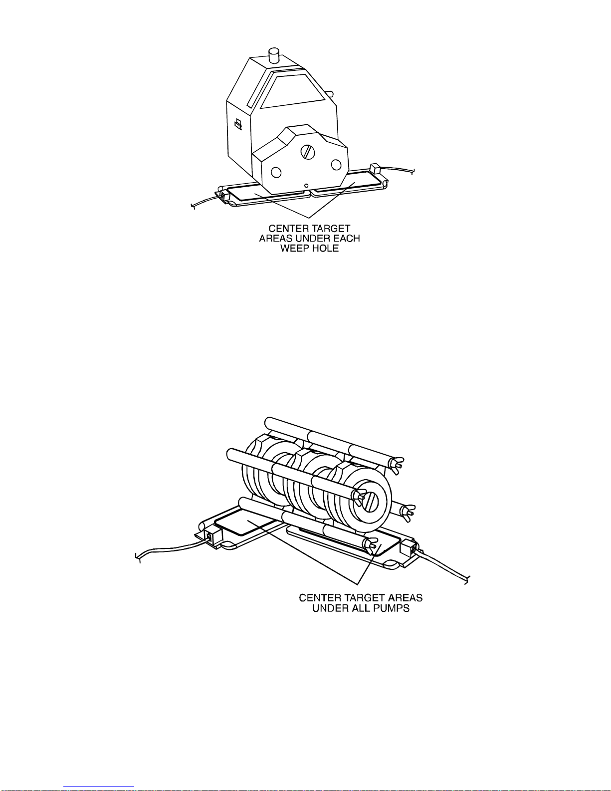
e.For typical standard stacked pumps where only one or two pumps
are used, a single detector can be centered under the stack of
pumps. When a larger number of pumps are used, two detectors
should be positioned to assure optimum leak detection as shown in
Figure 15.
12
Figure 14. Positioning two LIQUID-PAD Detectors under an
I/P EASY-LOAD Pump
Figure 15. Positioning two LIQUID-PAD Detectors under a
stack of Standard Pumps

5. If an Environment Monitor (such as a COLE-PARMER Model 08330) is
to be used or if another external device requiring a contact closure to
activate it is to be used, connect the 1/8-inch phone cable connector
from the rear panel CONTACT CLOSURE OUTPUT connector to the
external device.
6. Connect the LIQUID-SENSOR Controller POWER INPUT cord as
follows:
a.For 115V AC unit, connect line cord to 115V AC 50/60 Hz power
source.
b.For230VACunit,connectpowercablebetweenrearpanelPOWER
INPUT connector and 230V AC 50/60 Hz power source.
This completes the electrical connectors. Proceed with the OPERATION
Section.
OPERATION
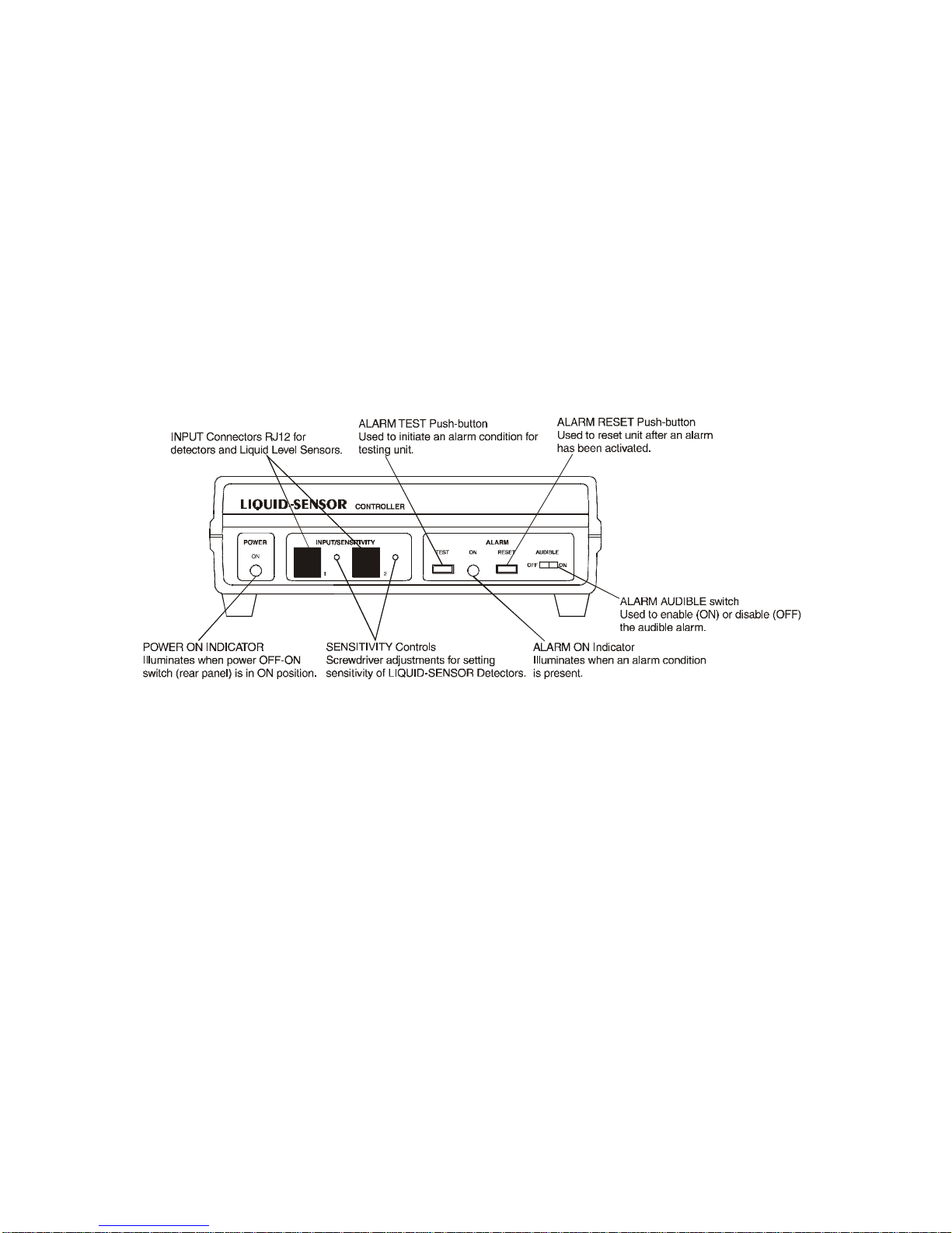
Operator Controls and Indicators
All operator controls except the power OFF-ON switch are located on the
front panel as shown in Figure 16. These controls and indicators are as
follows:
POWER ON IndicatorGreen LED illuminates when power
OFF-ON switch is in the ON position and
input power is present.
SENSITIVITY ControlsAdjusts the sensitivity of the circuit for use
with the LIQUID-PAD Detectors. (Pre-set at
factory for typical applications.)
ALARM TEST Momentary push-button. Tests the audible
alarm, the visual alarm, the switching of AC
power from the rear panel MAIN OUTPUT
to the AUXILIARY OUTPUT connectors and
the contact closure at the rear panel
CONTACT CLOSURE OUTPUT connector.
These are activated while the button is
pushed and reset automatically upon
release.
ALARM ON IndicatorRed LED illuminates when an alarm
condition is present.
13

ALARM RESET Momentary push-button. Resets alarm
circuits after alarm condition is removed
(detector pad wiped clean, tank filled, etc.).
While push-button is held in, the system
reverts to the non-alarm condition. If the
alarm condition is not cleared when the
ALARM RESET switch is released, the unit
will go back into the alarm condition. It may
be convenient to hold in the ALARM
RESET button while priming or purging the
system when a level detector is used.
ALARM AUDIBLE
OFF-ON SwitchIn the OFF position, the audible alarm will
not sound during an alarm condition. In the
ON position, the audible alarm will sound
during an alarm condition.
Power OFF-ON Rocker type switch located on rear panel.
Disconnects all AC power from unit and
from equipment connected to the MAIN
OUTPUT or AUXILIARY OUTPUT
connectors.
14
Figure 16. LIQUID-SENSOR Controller Front Panel

Startup Procedure
1. Check that all connections have been made as described in the
INSTALLATION Section.
2. Check that detectors are connected and properly positioned. Only one
detector can be connected to each channel. Use hook-and-loop fabric
fasteners to secure detector in position or, if permanent mounting is
desired, detector can be attached with #4 screws as described in the
INSTALLATION Section.
NOTE:Tubing may break at locations other than expected. Using a second
detector can provide for better detection.
3. Iftheaudible alarmistooperate,set ALARMAUDIBLEswitchtothe ON
position.Ifnoaudiblealarmisdesired,placeALARMAUDIBLEswitchin
the OFF position.
4. Set rear panel power OFF-ON switch to the ON position and check that
the front panel green POWER ON indicator is lit. The equipment should
now be operating normally.
5. If an alarm condition exists, proceed to the SENSITIVITY
ADJUSTMENTSection.Ifleveldetectorsareused,theymayneedtobe
inverted or rotated 180 °for proper operation. The audible alarm can be
turnedoffbyplacingtheALARMAUDIBLEswitchintheOFFposition.
6. Perform the LIQUID-PAD Detector Sensitivity Check using drops of the
same liquid used in your application.
Operational Checks
LIQUID-SENSOR CONTROLLER
An operational check of the LIQUID-SENSOR Controller can be performed
using the ALARM TEST switch. This test should be performed only when
temporary transfer of power from the MAIN OUTPUT connector to the
AUXILIARY OUTPUT connector will not be disruptive.
Proceed as follows:
1. Set the ALARM AUDIBLE switch to ON for the audible alarm to be
activated or to OFF to deactivate the audible alarm.
2. Set power OFF-ON switch to ON position and check that POWER ON
indicator is illuminated.
3. Press and hold the ALARM TEST SWITCH. Check that the audible
alarm sounds (if activated), the ALARM ON indicator is illuminated, that
power shifts from the MAIN OUTPUT connector to the AUXILIARY
OUTPUT connector and that the CONTACT CLOSURE OUTPUT
activates any equipment connected to the output.
15

LIQUID-PAD DETECTOR SENSITIVITY CHECK
The LIQUID-PAD Detector sensitivity may be checked as follows:
1. Connect detector to one of the front panel INPUT connectors, if not
already connected.
2. Place water one drop at a time on the detector pad. Do not drop water
from more than one inch.
3. Check number of drops required to activate alarm. Pre-set factory
setting should activate alarm with less than 1 mL of liquid. If activation
level is not as desired, refer to SENSITIVITY ADJUSTMENT Section.
4. After activating alarm, momentarily press then release the RESET
button. Alarm condition should still be present.
5. Wipe detector surface clean with a dry cloth and momentarily press,
then release, the RESET button. Alarm condition should terminate,
ALARM ON indicator should extinguish and, if activated, audible alarm
should turn off.
SENSITIVITY ADJUSTMENT
Generally, no sensitivity adjustment of the LIQUID-SENSOR Controller is
required. However, various liquids or environmental conditions such as
temperature and humidity may require adjustment of the SENSITIVITY
controls for use with the LIQUID-PAD Detectors. The SENSITIVITY
adjustment is accessed through the small hole adjacent to each INPUT
connector. Contact closure or logic level detectors do not require adjustment
of the SENSITIVITY control.
If the factory default setting for sensitivity is not activating the alarm, or is
falsely activating the alarm for the liquid being sensed, adjust the input
sensitivity with one channel connected at a time. Turn the SENSITIVITY
control clockwise to increase sensitivity (fewer drops will activate) or
counterclockwise to decrease sensitivity.
NOTE:If the sensitivity is increased so much that the red ALARM ON
indicator illuminates, the RESET button must be depressed each
time sensitivity is decreased until the indicator extinguishes.
Normal sensitivity adjustment is between one-quarter and two turns
counterclockwise from the activation point. The activation point is defined as
that sensitivity set when ALARM ON indicator just illuminates. Refer to Table
1 for typical sensitivity settings for various liquids. The middle column
indicatesthe number of turns counterclockwisefrom theactivation pointthat
16

the sensitivity control should be set for proper operation. The last column
indicates the quantity of fluid required in the target area of the detector to
activate the detector.
Sensitivity will change with detector position or when used near metallic
objects (e.g., table). Also, sensitivity changes when using longer (optional)
cables.
CAUTION:Use with caustic liquids not compatible with detector
materials voids warranty.
MAINTENANCE AND TROUBLESHOOTING
WARNING:No user serviceable parts are inside of this Controller.
Refer servicing to your dealer.
Fuse Replacement
The 115V AC LIQUID-SENSOR Controller uses a 10-A Slo-Blo fuse (3AG,
part number B-1115-0052), which is located in the fuse holder on the rear
panel. The 230V AC LIQUID-SENSOR Controller uses a 6.3-A fuse (5 x 20
mm, part number B-1115-0054), which is located in the drawer in the
POWER INPUT connector on the rear panel. Replace only with the correct
fuse.
Cleaning
Cleanthetopsurfaceofthedetectorpadwithasoft,drycloth.Ifliquidcleaner
is used, rinse and dry thoroughly before resuming operation. Keep the
LIQUID-SENSOR Controller enclosure clean by using a mild detergent.
Never immerse or use excess fluid.
17
Fluid TypeSetting (Turns ccw
from activation point)Nominal Volume
Distilled Water112< 1 mL
Tap Water112< 1 mL
Acetic Acid (10% max.)112< 0.5 mL
Alcohols112< 0.5 mL
Glycerin112< 2.0 mL
10W Motor Oil12< 2.0 mL
Table 1. Typical Sensitivity Settings

Troubleshooting
The following chart will help identify most problems that can be corrected by
the operator. If the fault cannot be located, return unit for servicing.
Troubleshooting Chart
SYMPTOMCAUSEREMEDY
POWER ON indicator
does not illuminate
with Power OFF-ON
switch in ON position
Fuse blownReplace fuse
Power cord not
plugged into active
power source
Plug in power cord
ALARM LIGHT
illuminates but audible
alarm does not sound
ALARM AUDIBLE
switch not set to ON
position
Set switch to ON
position
Alarm does not
activate for a fault
condition
Detector not connectedConnect detector
Sensitivity set too lowIncrease sensitivity
(LIQUID-PADDetector
only)
Detector cable
defectiveReplace cable
Detector inoperativeReplace detector
RESET button does
not reset unit when
depressed
Fault not clearedClear fault
Sensitivity set too
highLower sensitivity
(LIQUID-PAD Detector
only)
RESET button failureReturn unit for servicing
Alarm activated but
pump continues to
operate
Pump not connected
to MAIN OUTPUT
but directly to a
power source
Connect pump to MAIN
OUTPUT for shutdown
when an alarm
condition is sensed.
Alarm activated but
auxiliary pump does
not turn on
Auxiliary Pump not
connected to
AUXILIARY OUTPUT
Connect auxiliary pump
to AUXILIARY OUTPUT
18
This manual suits for next models
3
Table of contents
Popular Controllers manuals by other brands

MicroSet
MicroSet MS pH 97 instruction manual

Siemens
Siemens K60 4I/1O operating instructions

Veris Industries
Veris Industries G Series installation guide

Viessmann
Viessmann 4100 H0 Operation manual

Honeywell
Honeywell S05 Series installation instructions

omal automation
omal automation AE 10 instruction manual

ILX Lightwave
ILX Lightwave LDC-3900 user guide

Kolin
Kolin KAG-75WCINV user manual

MSR ELECTRONIC
MSR ELECTRONIC PolyGard SPC3-11 Series user manual

Rockwell Automation
Rockwell Automation Allen-Bradley 1756-L72EROMS installation instructions

ETAP
ETAP Easydim2 installation manual

Chromalox
Chromalox CTF-025 Quick start manual


