Barnes Synventive eGate 2.0 User manual

Elevate your process
HOT RUNNER TECHNOLOGY
eGate 2.0 Field Installation Guide
For Medium-to-Large Part Molding
®
SVC-16-0039_EN-Rev03
EN
08/ 2019

- 2 -
H O T R U N N E R T E C H N O L O G Y
eGate® 2.0 Field Installation Guide
EN
Master Language is English eGate® 2.0 Field Installation Guide SVC-16-0039_EN-Rev03
RESTRICTED: Property of Synventive
For limited third party distribution based on need
and intended use.
All rights reserved. Errors and omissions excepted.
© 2019 Synventive Molding Solutions
Introduction
Dear Customers,
Thank you for purchasing a Synventive eGate® System. Our objective is to provide you with a product that is a good t for the
application, trouble free in performance, and support it with the best service in the industry. If problems occur during the use of
this product, please contact us at one of the locations provided.
This manual is designed as a reference document for the proper installation, operation and maintenance of Synventive eGate®
Systems as well as a guideline for securing occupational health and safety in connection with the use of this system. Synventive
does not warrant that the information is complete or accurate for every application. Synventive reserves the right to make
changes to this document from time to time as new products are developed and new information identied.
This manual contains essential information, to ensure its general applicability to Synventive eGate® Systems. The customer is
exclusively responsible for the protection of their personnel and equipment. Synventive is not liable for any personal injury or
damage caused by improper use, installation or handling of the product. This product should only be installed and used by fully
trained and qualied personnel. The customer is required to provide the necessary personal protective equipment, such as
protective gloves, hearing protection, protective shields etc. In no case does this document provided by Synventive release the
customer from its obligations.
This manual is intended for tooling and molding personnel who install and maintain the eGate® System. It should be forwarded
with the eGate® System when shipped to the molder or between molding locations.
This document is copyright protected and it is intended exclusively for the users of Synventive eGate® Systems. It may not be
copied and distributed without the written consent of Synventive Molding Solutions.
Yours faithfully,
Synventive Molding Solutions
Headquarters:
USA – Peabody, MA
Synventive Molding Solutions Inc.
10 Centennial Drive
Peabody, MA 01960
Tel.: +1 978 750 8065
Fax: +1 978 646 3600
Email: [email protected]
Germany – Bensheim
Synventive Molding Solutions GmbH
Heimrodstraße 10
P. O. Box 3123
64625 Bensheim
Tel. :+49 (0)6251 9332-0
Fax :+49 (0)6251 9332-90
Email: [email protected]
China – Suzhou
Synventive Molding Solutions (Suzhou) Co. Ltd.
12B Gang Tian Industrial Square
Suzhou Industrial Park, China 215021
Tel.: +86 512 6283 8870
Fax: +86 512 6283 8890
Email: [email protected]
Customer Service:
The Americas
24/7 Technical Support Line
1-800-367-5662 – Press 4 from the Main Menu
Europe
Technical Support
+49 6251 93320 (8:00 am - 5:00 pm)
For after hours service, please contact your
local service representative
Asia
24/7 Technical Support
+86 512 62838870-866 (8:30 am - 5:00 pm)
+86 13862017765 after hours

- 3 -
H O T R U N N E R T E C H N O L O G Y
eGate® 2.0 Field Installation Guide
EN
Master Language is English eGate® 2.0 Field Installation Guide SVC-16-0039_EN-Rev03
RESTRICTED: Property of Synventive
For limited third party distribution based on need
and intended use.
All rights reserved. Errors and omissions excepted.
© 2019 Synventive Molding Solutions
Table of Contents
1 Safety Instructions............................................................................................................................................................. 4
1.1 CE approved Equipment .................................................................................................................................................. 4
1.2 Purpose of use of an eGate® Controller System for Hot Runners................................................................................ 4
1.3 Denition of Qualied Persons with Technical Knowledge............................................................................................. 4
1.4 Safety Instructions within the Instruction Manual ............................................................................................................ 5
1.5 eGate® System Instruction Manual ............................................................................................................................... 5
1.6 Safety Instructions and Symbols used............................................................................................................................. 6
1.7 General Safety Instructions............................................................................................................................................... 8
2 Preparing & Installing eGate® Components Product Specications...........................................................................10
2.2 eGate® Component Overview....................................................................................................................................... 11
2.3 Controller Installation.......................................................................................................................................................12
2.4 Drive Box Installation.......................................................................................................................................................13
2.5 Junction Box Installation .................................................................................................................................................14
3 Connecting eGate® Components..................................................................................................................................15
3.1 eGate® Installation Overview.........................................................................................................................................16
4 Service Instructions......................................................................................................................................................... 17
4.1 Actuator Removal Procedure .........................................................................................................................................18
4.2 Fuses & Circuit Breakers................................................................................................................................................ 19
5 Annex...............................................................................................................................................................................20
5.1 Disposal ...........................................................................................................................................................................20
5.2 Patents.............................................................................................................................................................................20
5.3 Global Ofces / Sales Agencies ..................................................................................................................................... 21

- 4 -
H O T R U N N E R T E C H N O L O G Y
eGate® 2.0 Field Installation Guide
EN
Master Language is English eGate® 2.0 Field Installation Guide SVC-16-0039_EN-Rev03
RESTRICTED: Property of Synventive
For limited third party distribution based on need
and intended use.
All rights reserved. Errors and omissions excepted.
© 2019 Synventive Molding Solutions
Safety Instructions
1 Safety Instructions
1.1 CE approved Equipment
●Only CE approved equipment rated for application should be used with Synventive Hot Runner Systems.
1.2 Purpose of use of an eGate® Controller System for Hot Runners
1.2.1 Use compatible with the intended Purpose
● The goal of the Synventive eGate® Hot Runner System is to carefully transport the melt from the plastication
unit to the cavity with an optimum temperature distribution and optimum distribution concept.
●Synventive eGate® Controller System for Hot Runners are not stand alone systems and must be incorporated in
the injection mold for use.
●All Synventive eGate® Controller System for Hot Runners are used exclusively for the processing of
thermoplastic materials based on the individual requirements of the specied material.
●A max. injection pressure of 30,000 psi (2068 bar) applies to Synventive Hot Runner standard components
(unless otherwise stated).
● Use in conformity with the specied purpose also includes the study and understanding of and the compliance
with all instructions and tasks of the submitted instructions for use.
●Synventive eGate® Hot Runner Systems may be incorporated only into specially designed cavities of injection
molds.
●To guarantee a reliable operation of the Synventive eGate® Controller System for Hot Runners, it is necessary to
comply with the specied periodic inspections and regular maintenance.
1.2.2 Use in conict with the intended Purpose
●Synventive eGate® Controller System for Hot Runner may be only used in the manner described in section 1.2.1
Use compatible with the intended Purpose. Any other use is excluded. If the eGate® Controller System for Hot
Runner System is used in any manner that contradicts the intended purpose, the right to any warranty claims
shall cease to exist.
1.3 Denition of Qualied Persons with Technical Knowledge
Technical knowledge means that personnel must -
●Be capable of reading and fully understand electrical/hydraulic circuits
●Fully understand the interrelationship of the built-in safety systems
●Have knowledge regarding the function and build-up of technical components.
A qualified person is one who, due to his technical training and experience, has sufficient knowledge
that he can evaluate the work transferred -
●Can recognize possible hazards.
●Can instigate measures to eliminate hazards.
●has the required repair and assembly knowledge.

- 5 -
H O T R U N N E R T E C H N O L O G Y
eGate® 2.0 Field Installation Guide
EN
Master Language is English eGate® 2.0 Field Installation Guide SVC-16-0039_EN-Rev03
RESTRICTED: Property of Synventive
For limited third party distribution based on need
and intended use.
All rights reserved. Errors and omissions excepted.
© 2019 Synventive Molding Solutions
Safety Instructions
1.4 Safety Instructions within the Instruction Manual
●The Synventive eGate® Controller System for Hot Runners is an incomplete machine. When the eGate® Controller
System is tted into a machine, the interaction between the entire machine and the eGate® Controller System,
causes changes to the potential hazards. In particular, the inuence of electrical controls which cause mechanical
movements. This necessitates a hazard analysis and operating instructions for the entire machine.
●These operating instructions are intended to provide information and to prevent hazards when installing the eGate®
Controller System for Hot Runners in the machine as well as information and guidelines for transport, storage and
maintenance (inspection, servicing, repair) of the eGate® Controller System.
●Only by strictly observing these operating instructions, is it possible to prevent accidents and material damage and
ensure fault-free operation of the eGate® Controller System for Hot Runners.
1.5 eGate® System Instruction Manual
●Comply with all safety instructions contained in the customer drawings.
●Use customer drawings for general information only. For detailed information, refer to the supplied Synventive 3D
model.
Parts of the Synventive customer documentation are:
●User Guide
●Field Installation Guide
●Customer drawings
●Electrical wiring information
● Product Certicate / Hot Runner Check List
●Manifold mounting check list
●Parts list
●3D-Model (in digital form)
●General safety instruction for the Synventive Hot Runner Systems

- 6 -
H O T R U N N E R T E C H N O L O G Y
eGate® 2.0 Field Installation Guide
EN
Master Language is English eGate® 2.0 Field Installation Guide SVC-16-0039_EN-Rev03
RESTRICTED: Property of Synventive
For limited third party distribution based on need
and intended use.
All rights reserved. Errors and omissions excepted.
© 2019 Synventive Molding Solutions
Safety Instructions
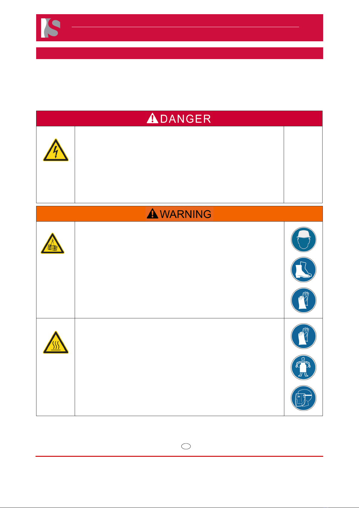
1.6 Safety Instructions and Symbols used
The following safety instructions and symbols and operating advice are used in this manual. They are highlighted by the respective
word. The described measures are used to prevent injuries and avoid damage to the eGate® Controller System and must be followed.
1.6.1 Danger Symbols Denitions
Danger
indicates an imminent hazardous situation which may result in death or serious injury.
Warning
indicates a dangerous situation that may lead to irreversible injury.
Caution
indicates a dangerous situation that may lead to reversible injury.
Notice
indicates a situation that may lead to material damage and provides additional
information on proper procedures and trouble-free labor without the possibility of
personal injury.
1.6.2 Mandatory Safety Signs of the Personal Protective Equipment
Read the user
instruction
Wear safety shoes Wear close-tting
working cloth
Wear headgear Wear protective
goggles
Wear face protection
Wear work gloves Wear apron against
high temperature
Wear hearing
protection
1.6.3 Warning Symbols
General warning Warning of electrical
danger
Warning of hot surface
Warning of overhead
load
Warning of fork lift
trucks operating
Warning of falling
objects

- 7 -
H O T R U N N E R T E C H N O L O G Y
eGate® 2.0 Field Installation Guide
EN
Master Language is English eGate® 2.0 Field Installation Guide SVC-16-0039_EN-Rev03
RESTRICTED: Property of Synventive
For limited third party distribution based on need
and intended use.
All rights reserved. Errors and omissions excepted.
© 2019 Synventive Molding Solutions
Safety Instructions
1.6.4 Product Safety Label
Electrical danger
1.6.5 Electrical Symbol
Potential earth ground
1.6.6 Components of the Synventive eGate® Controller System
●Injection Molding Machine (IMM) is CE approved according 2006/42/EG, 2004/108/EG, 2006/95/EG
●eGate®Hot Runner System is CE approved according 2006/42/EG, 2004/108/EG, 2006/95/EG,
EN ISO 12100 -1:2003/A1:2009, EN ISO 12100-2:2003/A1:2009, EN 60204-1:2006, EN 61000-6-4:2007
●eGate®Controller System is CE approved according: EN 60204-1:2010, EN ISO12100:2010, EN 61010-1:2010
- 8 -
H O T R U N N E R T E C H N O L O G Y
eGate® 2.0 Field Installation Guide
EN
Master Language is English eGate® 2.0 Field Installation Guide SVC-16-0039_EN-Rev03
RESTRICTED: Property of Synventive
For limited third party distribution based on need
and intended use.
All rights reserved. Errors and omissions excepted.
© 2019 Synventive Molding Solutions
Safety Instructions
1.7 General Safety Instructions
All safety instructions shall be carefully studied before the operation of the Synventive eGate® Controller System for Hot Runner is
initiated. When working with the Hot Runner System, all safety instructions contained here in must be followed.
Noncompliance with safety notes and instructions could result in serious injuries.
Danger to Life by Electric Shock
The electrical cables connected to the Controller System, Injection Molding Machine and
Hot-Runner are under high voltage.
Serious personal injury or death can result from electrical contact.
Electrical work must be carried out by qualied persons.
Verify that all power source connections are properly grounded.
In emergency case - Switch all systems off.
For rst aid contact your medical / safety representing.
Heavy Weight Hazard
Transport and lifting equipment should be operated only by trained personnel.
Use personal protective equipment, such as head gear, safety shoes and work gloves.
Operate lifting and transport equipment slowly and carefully to avoid uncontrolled
swinging of the manifold.
Lifting and transport equipment for lifting Hot Runner Systems shall be approved and
properly rated taking into account the weight and size of the manifold.
For rst aid contact your medical / safety representing.
Hot Surfaces Hazard
Contact between the skin and the hot injection mold could result in burns.
Use personal protective equipment, such as work gloves, apron, sleeves and face
protection, to guard against burns.
When servicing or handling the hot runner system outside the manifold plates or the
injection molding machine, care must be taken to heed the hot surface exposure
warnings.
For rst aid contact your medical / safety representing.

- 9 -
H O T R U N N E R T E C H N O L O G Y
eGate® 2.0 Field Installation Guide
EN
Master Language is English eGate® 2.0 Field Installation Guide SVC-16-0039_EN-Rev03
RESTRICTED: Property of Synventive
For limited third party distribution based on need
and intended use.
All rights reserved. Errors and omissions excepted.
© 2019 Synventive Molding Solutions
Safety Instructions
Danger of Material Defects
Only approved and CE certied temperature controllers rated for application with over current / voltage protection should be used
with Hot Runner Systems.
Verify that all cables are damage free and in good condition.
Verify that all electrical connectors are clean and making good contact, and are securely fastened and latched. Dirty or otherwise
contaminated connector pins can cause loss of signal and subsequent errors.
Clean all connectors with a spray-type commercial electrical contact cleaner / degreaser and allow them to dry fully before
reconnecting.
All Synventive Hot Runner Systems shall be tted with a temperature controller to provide separate temperature adjustment for
each heating zone; the controller shall have the Soft-Start function for gradual heat-up. In this way you can prevent premature
wearing and damage to the hot runner system.
To extend the lifetime of temperature sensors, avoid long-term operation of temperature control in manual mode.
Immediately replace defective temperature sensors.
If you replace heaters or their parts, always use original spare parts from Synventive and carry out the replacement as described
in this manual.
Do not interchange power supply cables with temperature sensor cables. Temperature sensor cables are not suitable for high
voltage applications and will melt if exposed to high currents. Power supply cables are not suitable for use as temperature sensor
cables for data transfer to the temperature controller.
To maximize the life of temperature sensors, maintain the operating temperature as specied in the respective material safety
data sheets during processing.
Take notice of the production and color identication of temperature sensor cables.
Always use the specied temperature sensor.
Check that the aluminium surfaces of heaters do not come in contact to the nozzle cutouts. If they do, enlarge the nozzle cutouts
as needed. Any contact between the heaters and the nozzle cutouts will lead to the risk of improper temperature control, which
could result in damage to the aluminum casting.
If applicable, set the necessary operating temperature to the lowest level possible to avoid plastic degradation and to prevent
damage to the temperature sensors.
The cooling compound for nozzles with a cooling insert should always have the correct mixing ratio to prevent corrosion and
obstructed circulation.
- 10 -
H O T R U N N E R T E C H N O L O G Y
eGate® 2.0 Field Installation Guide
EN
Master Language is English eGate® 2.0 Field Installation Guide SVC-16-0039_EN-Rev03
RESTRICTED: Property of Synventive
For limited third party distribution based on need
and intended use.
All rights reserved. Errors and omissions excepted.
© 2019 Synventive Molding Solutions
Preparing & Installing eGate® Components
2 Preparing & Installing eGate®Components
2.1 Product Specications
Item eGate®Controller
Zone Count 8-Zone Controller: 1 – 8 Zones
16-zone Controller: 1 – 16 Zones
System Weight
8-Zone Controller: 120 lbs (54.4 kg)
16-Zone Controller: 137 lbs (62.1 kg)
2-Zone Drive Box: 23 lbs (10.4 kg)
4-Zone Drive Box: 46 lbs (20.9 kg)
6-Zone Drive Box: 68 lbs (30.8 kg)
8-Zone Drive Box: 90 lbs (40.8 kg)
Note: Drive Boxes are daisy-chained in order to achieve zone counts higher than 8-zones.
Mains Connection:
220-240 VAC, 1 phase, 50/60 Hz
8-Zone Controller: 20 amp
16-zone Controller: 40 amp
Environmental
Conditions:
Operating temperature: 0 – 43 °C (32 - 110 °F) IP32
Storage temperature: -40 to 85 °C (-40 - 185 °F)
Relative humidity: 0-80% non-condensing

- 11 -
H O T R U N N E R T E C H N O L O G Y
eGate® 2.0 Field Installation Guide
EN
Master Language is English eGate® 2.0 Field Installation Guide SVC-16-0039_EN-Rev03
RESTRICTED: Property of Synventive
For limited third party distribution based on need
and intended use.
All rights reserved. Errors and omissions excepted.
© 2019 Synventive Molding Solutions
Preparing & Installing eGate® Components
2.2 eGate® Component Overview
Controller and Tablet Assembly
ELA2-08ZC02-K01 (8-zone)
ELA2-16ZC02-K01 (16-zone)
ELA2-08ZC02P-K01
(8-zone, with Priamus triggering)
ELA2-16ZC02P-K01
(16-zone, with Priamus triggering)
Controller to Drive Box Power Cable ELALCDC0204 (2 m long)
ELALCDC0504 (5 m long)
ELALCDC0804 (8 m long)
ELALCDC1504 (15 m long)
Controller to Drive Box Digital
Communication Cable
TRG502-T4T-1m (1 m long)
TRG502-T4T-5m (5 m long)
TRG502-T4T-10m (10 m long)
Controller to IMM Cable ELAIMMC4572-03 (4.6 m long)
ELAIMMC7620-03 (7.6 m long)
ELAIMMC15000-03 (15 m long)
Drive Box ELA2-LDRVBOX##
## = 02,04,06,08 (zones)
One 8-zone Drive Box plus applicable
2, 4, 6, or 8-zone Drive Box, then ## =
10,12,14,16 (zones)
Junction Box to Drive Box Cable ELALJDC0204 (2 m long)
ELALJDC0504 (5 m long)
ELALJDC0804 (8 m long)
ELALJDC1504 (15 m long)
Junction Box
ELA2-08LJB-01 (8-zone)
ELA2-16LJB-01 (16-zone)
Electric Actuator Assembly ELA761602M0# # = 1, 3, 6
(1 m,3 m,6 m long cable cong.)
a) Linear Motion Converter LCA02-01
b) Motor assembly ELA7616-#000 # = 1, 3, 6
(1 m, 3 m, 6 m long cable cong.)
c) Cooling Jacket ELA7616-WJA-01

- 12 -
H O T R U N N E R T E C H N O L O G Y
eGate® 2.0 Field Installation Guide
EN
Master Language is English eGate® 2.0 Field Installation Guide SVC-16-0039_EN-Rev03
RESTRICTED: Property of Synventive
For limited third party distribution based on need
and intended use.
All rights reserved. Errors and omissions excepted.
© 2019 Synventive Molding Solutions
Preparing & Installing eGate® Components
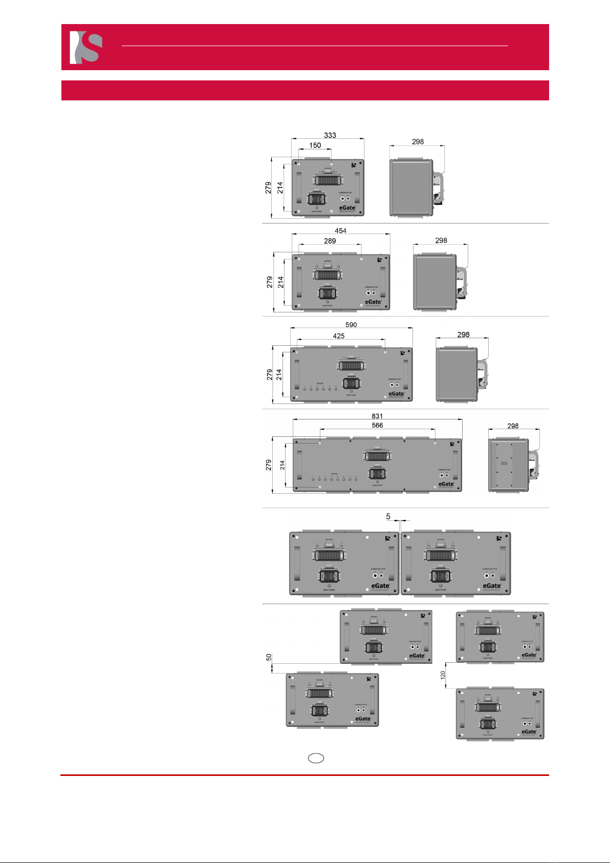
2.3 Controller Installation
The eGate® Controller which includes a Tablet with pre-
installed eShop Software, is designed to be put on the ground
beside the Injection Molding Machine (IMM), preferably on the
operator side.
In order to ensure sufcient ventilation of the Controller,
please ensure a minimum installation space according to the
illustrations.
●Ensure that mold release spray and residue
from plastic grinding do not come in proximity
of the Controller.
●Apply the brakes on the Controller when an
appropriate location has been choosen.
Doc007818.png
Doc007819.png
The Tablet can be removed from the Controller and mounted
on the Injection Molding Machine via Magnets included on the
back of the Tablet Enclosure.
NOTICE
●The cable must reach the controller and
should be protected from excessive heat and
mechanical damage.
●The tablet may be repositioned or removed at
any time.
Doc007611.png
Doc007624.png
- 13 -
H O T R U N N E R T E C H N O L O G Y
eGate® 2.0 Field Installation Guide
EN
Master Language is English eGate® 2.0 Field Installation Guide SVC-16-0039_EN-Rev03
RESTRICTED: Property of Synventive
For limited third party distribution based on need
and intended use.
All rights reserved. Errors and omissions excepted.
© 2019 Synventive Molding Solutions
Preparing & Installing eGate® Components
2.4 Drive Box Installation
The Drive Box is designed to be ideally mounted
on the Injection Molding Machine (ideally near
Top Operator side) via four M10 Socket Head
Cap Screws. Consult Synventive prior to nalizing
mounting location.
The Drive Boxes can be mounted either horizontal
or vertical orientations.
Two Drive Boxes are required for any application
requiring more than 8 Electric Actuators. In this
conguration:
●The Communication Port from each
Drive Box would be daisy-chained.
●Each Drive Box Power/Sensor
Cable would be connected to the
applicable eGate® Junction Box.
●Each Drive Box Main Power
Cable would be connected to the
applicable Power Connector on the
eGate® Controller.
ELA2-LDRVBOX02
(2-Zone)
ELA2-LDRVBOX04
(4-Zone)
ELA2-
LDRVBOX06
(6-Zone)
ELA2-LDRVBOX08 (8-Zone)

- 14 -
H O T R U N N E R T E C H N O L O G Y
eGate® 2.0 Field Installation Guide
EN
Master Language is English eGate® 2.0 Field Installation Guide SVC-16-0039_EN-Rev03
RESTRICTED: Property of Synventive
For limited third party distribution based on need
and intended use.
All rights reserved. Errors and omissions excepted.
© 2019 Synventive Molding Solutions
Preparing & Installing eGate® Components
2.5 Junction Box Installation
Since eGate® Hot Runner Systems are supplied pre-wired
and pre-plumbed with a customized wireguard, the Junction
Box is mounted to the Synventive wireguard. The connections
on the Junction Box include the motor power and encoder
signals.
The Junction Box is available in 8-zone and 16-zone
congurations.
The eGate® Junction Box allows the attachment of up to 8
Electric Actuators per connector to the Synventive eGate®
Drive box.
In order to ensure Actuator Connectors do not interfere with
other mold components, please ensure a minimum installation
space according to the illustrations
Doc007808.png
Doc007809.png

- 15 -
H O T R U N N E R T E C H N O L O G Y
eGate® 2.0 Field Installation Guide
EN
Master Language is English eGate® 2.0 Field Installation Guide SVC-16-0039_EN-Rev03
RESTRICTED: Property of Synventive
For limited third party distribution based on need
and intended use.
All rights reserved. Errors and omissions excepted.
© 2019 Synventive Molding Solutions
Connecting eGate® Components
3 Connecting eGate® Components
The eGate® components are connected to the Controller via cables.
NOTICE
All connections must be made or broken with the power off.
Make the connections as follows:
1) Establish a connection with the Cable (ELALJDC##04) between the Junction
box and the Drive box.
## = 02, 05, 08, 15 (m) Cable lengths
Doc007830.png
2) Establish connections with power Cable (ELALCDC##04) and Communication
cable (TRG502-T4T- #m) between the Controller and the Drive Box.
## = 02, 05, 08, 15 (m) Cable lengths
# = 1, 5, 10 Cable lengths
Doc007831.png
3) Connect the IMM Interface cable (ELAIMMC####-03) between the Controller
and the IMM.
ELAIMMC4572-03 (4.6 m Cable length)
ELAIMMC7620-03 (7.6 m Cable length)
ELAIMMC15000-03 (15 m Cable length)
Doc007832.png
4) Connect the controller Power Cord to the main 220-240VAC power source.
NOTICE
●Install the necessary power plug (supplied by customer) on the end
of the Power Cord.
●Synventive recommends an industrial Power Plug with minimum
rating of:
●250V, 30A, 50-60Hz per IEC 60309 for an 8-Zone Controller
●250V, 60A, 50-60Hz per IEC 60309 for a 16-Zone Controller
●Failure to connect ground will result in system malfunction.
●Contact Synventive if the Power source is lless than or greater than
220-240V.
●Reference the eGate® User Guide for next steps.
Doc007833.png
NOTICE
The Actuator assembly is supplied pre-connected by Synventive for all pre-wired systems with pre-plumbed cooling
circuits. Max. number of motors for cooling circuits are 3.

- 16 -
H O T R U N N E R T E C H N O L O G Y
eGate® 2.0 Field Installation Guide
EN
Master Language is English eGate® 2.0 Field Installation Guide SVC-16-0039_EN-Rev03
RESTRICTED: Property of Synventive
For limited third party distribution based on need
and intended use.
All rights reserved. Errors and omissions excepted.
© 2019 Synventive Molding Solutions
Connecting eGate® Components
3.1 eGate® Installation Overview
Up to 8 Zones system Greater than 8 zones system
Doc007834.png Doc007835.png
Doc007836.png

- 17 -
H O T R U N N E R T E C H N O L O G Y
eGate® 2.0 Field Installation Guide
EN
Master Language is English eGate® 2.0 Field Installation Guide SVC-16-0039_EN-Rev03
RESTRICTED: Property of Synventive
For limited third party distribution based on need
and intended use.
All rights reserved. Errors and omissions excepted.
© 2019 Synventive Molding Solutions
Service Instructions
4 Service Instructions
WARNING
It is necessary to turn off the Controller Main Power Switch and unplug the Controller from
the main power source and lock the plug end of the power cord with a Shackle (examples
shown to the right) prior to doing any service on the eGate® control system.
Lock and Tag out Procedures for Electrical Plug-Type Equipment:
When working on, repairing, or adjusting electrical plug-type equipment, the following procedures must be utilized to prevent accidental
or sudden start-up:
●Turn off Controller Main Power Switch.
●Un-plug Controller from wall socket or in-line socket.
●Place Shackle over Power Cord, and lock the Shackle.
●Place locks and tags on all stored energy isolating devices that are capable of accepting a lockout device. Tags
cannot replace locks. Tags will be attached securely at the same location that the lockout devices would have been
attached. Where a tag cannot be attached directly to the energy isolating device, the tack will be attached as close
as possible and so that it would be immediately obvious to anyone attempting to operate the equipment.
●Test equipment to ensure power source has been removed by switching system to “On”.
●While keeping load side of plug within direct and immediate view, perform requierd operations.
●Inspect power cord and socket before removing Tag. Any defects must be repaired before placing the equipment back
in service.
●Remove Tag and place equipment back in service.
WARNING
Allow a minimum of 5 minutes after power has been disconnected prior to servicing equipment. Some circuits remain
active via charged capacitors (so 5 minutes are required in order to ensure the capacitors have been discharged).

- 18 -
H O T R U N N E R T E C H N O L O G Y
eGate® 2.0 Field Installation Guide
EN
Master Language is English eGate® 2.0 Field Installation Guide SVC-16-0039_EN-Rev03
RESTRICTED: Property of Synventive
For limited third party distribution based on need
and intended use.
All rights reserved. Errors and omissions excepted.
© 2019 Synventive Molding Solutions
Service Instructions
4.1 Actuator Removal Procedure
1) Turn off the eGate® Controller power.
NOTICE
Failure to turn off power prior to starting this
procedure can lead to severe Controller damage.
2) Disconnect the power and signal connectors from the
Junction Box for each Actuator to be removed.
Step 1:
Remove the 4 screws
Step 2:
Pull out the connectors assembly
Doc007837.png Doc007838.png
Step 3:
Remove the 4 small screws
Step 4:
Remove and slide out the signal
and power connectors
Doc007839.png Doc007840.png
3) Remove the 4 screws from Linear Motion Converter that
retain the Actuator on the Manifold Plate.
Hot Surfaces Hazard
Contact between the skin and hot surfaces will
result in burns.
NOTICE
It is necessary to heat the Hot Runner system
to operating temperature if there is plastic in the
Hot Runner system so that the Valve Pin can be
safely removed.
4) Slide the Actuator to unlock the Valve pin.
Doc007803.png
Doc007841.png
Doc007842.png

- 19 -
H O T R U N N E R T E C H N O L O G Y
eGate® 2.0 Field Installation Guide
EN
Master Language is English eGate® 2.0 Field Installation Guide SVC-16-0039_EN-Rev03
RESTRICTED: Property of Synventive
For limited third party distribution based on need
and intended use.
All rights reserved. Errors and omissions excepted.
© 2019 Synventive Molding Solutions
Service Instructions
5) Pull and remove the Actuator as shown.
Doc007843.png
Remove the Motor from the Motion Converter
1) Remove the 2 screws as right picture shows.
Doc007844.png
2) Remove the Motor assembly.
Doc007846.png
4.2 Fuses & Circuit Breakers
Reference Fuse Kit located inside of Controller Door and Troubleshooting Guide for information regarding Fuses and Circuit Breakers.

- 20 -
H O T R U N N E R T E C H N O L O G Y
eGate® 2.0 Field Installation Guide
EN
Master Language is English eGate® 2.0 Field Installation Guide SVC-16-0039_EN-Rev03
RESTRICTED: Property of Synventive
For limited third party distribution based on need
and intended use.
All rights reserved. Errors and omissions excepted.
© 2019 Synventive Molding Solutions
Annex
5 Annex
5.1 Disposal
Disposal of eGate® systems should involve the recycling of basic materials. Synventive rejects any responsibility for health and safety
risks to personnel or other damages caused by the re-use of individual parts for a purpose other than the originally specied purpose.
●Remove electrical components (heating, temperature sensors) and process through your recycling program.
●Dismantle cables and dispose them in accordance with local environmental regulations.
NOTICE
Metal parts must be separated for recycling (scrapping, collection points).
It is necessary to comply with the instructions from competent firms authorized to dispose of the specific materials.
5.2 Patents
Please note the copyright protection reminder pursuant to DIN ISO 16016. The specied patents are the property of Synventive
Molding Solutions. Their distribution and dissemination is permitted only subject to approval.
The products are protected by US, CA, CN, JP and European Community patents published on WEB.
http://www.synventive.com/Patents.aspx?terms=us%20patents
Property of Synventive. Not for third parties without written permission.
Table of contents
Other Barnes Industrial Equipment manuals


