Barnstead International MaxQ 4000 User manual
MaxQ 4000
Incubated and
Refrigerated Shakers
MODEL NO.
SHKA4000
SHKA4000-1CE
SHKA4000-5
SHKA4000-6CE
SHKA4000-7
SHKA4000-8CE
SHKE4000
SHKE4000-1CE
SHKE4000-5
SHKE4000-6CE
SHKE4000-7
SHKE4000-8CE
057-287-00 • 8/9/06
2
Table of Contents
Safety Information ..............................................................................................................................................3
Alert Signals ................................................................................................................................................3
Warnings ......................................................................................................................................................3
General Specifications ........................................................................................................................................5
Environmental Operating Conditions ........................................................................................................10
Declaration of Conformity ..........................................................................................................................10
A-Class, Control Panel ..............................................................................................................................11
E-Class, Control Panel ..............................................................................................................................12
Unpacking and Installation ..............................................................................................................................13
Shipping Carton ........................................................................................................................................13
Unpacking ..................................................................................................................................................13
Location ....................................................................................................................................................13
Electrical Requirements ............................................................................................................................14
Platform Installation ..................................................................................................................................15
Flask Clamp Installation ............................................................................................................................15
Test Tube Rack Installation ......................................................................................................................16
Operation ........................................................................................................................................................17
A-Class ......................................................................................................................................................17
Power Switch ........................................................................................................................................17
Speed Control and Display ....................................................................................................................17
Time(r) ....................................................................................................................................................17
Temperature Controller - Setting Temperature ......................................................................................18
Temperature Calibration ........................................................................................................................18
E-Class ......................................................................................................................................................20
Turning Shaker On..................................................................................................................................20
Setting Shaking Speed ........................................................................................................................20
Calibrating Shaking Speed ..................................................................................................................20
Setting Operating Temperature ............................................................................................................21
AC Power Loss ....................................................................................................................................21
Temperature Calibration ........................................................................................................................22
Setting Timer for Timed Shaking ..........................................................................................................23
Setting Timer for Continuous Shaking ..................................................................................................23
RS232 Interface ....................................................................................................................................24
Hyperterminal Configuration ..................................................................................................................24
Setting High-Limit Control ....................................................................................................................25
Setting Low-Limit Control, Refrigerated Units ......................................................................................26
Optional Refrigeration System ..............................................................................................................27
Maintenance ....................................................................................................................................................29
Troubleshooting ................................................................................................................................................30
Replacement Parts............................................................................................................................................31
Wiring Diagrams ....................................................................................................................................33
Ordering Procedures ........................................................................................................................................34
Warranty ..........................................................................................................................................................36
3
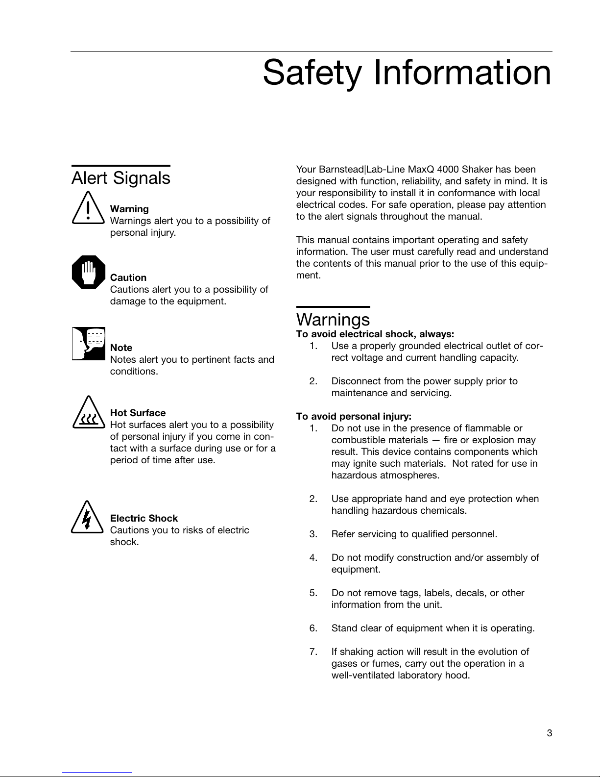
Safety Information
Warning
Warnings alert you to a possibility of
personal injury.
Caution
Cautions alert you to a possibility of
damage to the equipment.
Note
Notes alert you to pertinent facts and
conditions.
Hot Surface
Hot surfaces alert you to a possibility
of personal injury if you come in con-
tact with a surface during use or for a
period of time after use.
Alert Signals Your Barnstead|Lab-Line MaxQ 4000 Shaker has been
designed with function, reliability, and safety in mind. It is
your responsibility to install it in conformance with local
electrical codes. For safe operation, please pay attention
to the alert signals throughout the manual.
This manual contains important operating and safety
information. The user must carefully read and understand
the contents of this manual prior to the use of this equip-
ment.
Warnings
To avoid electrical shock, always:
1. Use a properly grounded electrical outlet of cor-
rect voltage and current handling capacity.
2. Disconnect from the power supply prior to
maintenance and servicing.
To avoid personal injury:
1. Do not use in the presence of flammable or
combustible materials — fire or explosion may
result. This device contains components which
may ignite such materials. Not rated for use in
hazardous atmospheres.
2. Use appropriate hand and eye protection when
handling hazardous chemicals.
3. Refer servicing to qualified personnel.
4. Do not modify construction and/or assembly of
equipment.
5. Do not remove tags, labels, decals, or other
information from the unit.
6. Stand clear of equipment when it is operating.
7. If shaking action will result in the evolution of
gases or fumes, carry out the operation in a
well-ventilated laboratory hood.
Electric Shock
Cautions you to risks of electric
shock.
4
SAFETY INFORMATION
8. Use equipment only for its intended purpose.
Use only the accessories and attachments that
are shipped with the equipment or are specified
for it. Substituting other attachments or acces-
sories can produce hazards or make the unit
inoperative.
9. Perform regular maintenance service as speci-
fied in this manual and keep unit in good repair.
Do not operate with known defects.
10. Do not use the shaker to mix flammable materi-
als or where the transfer of mechanical energy
to glass could cause glass breakage.

5
General Specifications
Model number All Analog
“A” Series units
All Analog
“A” Series units
All Digital
“E” Series units
All Digital
“E” Series units
Length 32” (81.3 cm) 32” (81.3 cm) 32” (81.3 cm) 32” (81.3 cm)
Width 22.5” (57.2 cm) 22.5” (57.2 cm) 22.5” (57.2 cm) 22.5” (57.2 cm)
Height 22” (55.9 cm) 22” (55.9 cm) 22” (55.9 cm) 22” (55.9 cm)
Exterior Unit Dimensions
Model number All Analog
“A” Series units
All Analog
“A” Series units
All Digital
“E” Series units
All Digital
“E” Series units
Voltage AC 120 220-240 120 220-240
Amperage 5.0 3.0 5.0 2.5
Wattage 625 725 625 625
Frequency 60 50/60 60 50/60
Voltage AC 120 220-240 120 220-240
Amperage 9.0 5.0 9.0 4.5
Wattage 1100 1200 1100 1100
Frequency 50/60 50/60 50/60 50/60
Voltage AC 120 220-240 120 220-240
Amperage 14.0 7.0 14.0 7.0
Wattage 1500 1500 1500 1500
Frequency 60 50 60 50
Electrical - Standard Temperature
Refrigerated
High Temperature
Weight 120 lbs (54.4 kg) 120 lbs (54.4 kg) 165 lbs (74.9 kg) 165 lbs (74.9 kg)
6
GENERAL SPECIFICATIONS
Speed Accuracy 40 to 400 rpm 40 to 400 rpm 15 to 500 rpm
±1 rpm
15 to 500 rpm
±1 rpm
Timer Continuous or timed
operation from 1-60
min.
Continuous or timed
operation from 1-60
min.
Continuous or timed
operation 0.1-999
hours or 0.1-999
mins.
Continuous or timed
operation 0.1-999
hours or 0.1-999
mins.
Display
3 individual LED
displays indicate
temperature in 1°C
increments. Analog
tachometer displays
speed in rpm.
3 individual LED
displays indicate
temperature in 1°C
increments. Analog
tachometer displays
speed in rpm.
3 individual LED
displays indicate
temperature, time
and speed simulta-
neously. 3 charac-
ters height 1/2
inch (1.27 cm)
3 individual LED
displays indicate
temperature, time
and speed simulta-
neously. 3 charac-
ters height 1/2
inch (1.27 cm)
Mutable Alarms None None
Audible portion of
the alarm can be
silenced for a period
of 1 hour without
deactivating the
actual alarm
condition by
depressing any key.
Audible portion of
the alarm can be
silenced for a period
of 1 hour without
deactivating the
actual alarm
condition by
depressing any key.
Motor Permanent Magnet
DC
Permanent Magnet
DC
Solid State
Brushless DC
Solid State
Brushless DC
Soft Start Feature None None
Software algorithms
prevent sudden
start/stops.
Software algorithms
prevent sudden
start/stops.
RS232 Interface * None None
Monitor speed,
temperature in °C
and time with a
computer.
Monitor speed,
temperature in °C
and time with a
computer.
Recorder Output * None None
10 mv/°C output
monitors tempera-
ture with external
chart recorder.
10 mv/°C output
monitors tempera-
ture with external
chart recorder.
Model number All Analog
“A” Series units
All Analog
“A” Series units
All Digital
“E” Series units
All Digital
“E” Series units
* Interface cables not to exceed 9.8 ft. (3 m) in length.
7
GENERAL SPECIFICATIONS
Model number All Analog
“A” Series units
All Analog
“A” Series units
All Digital
“E” Series units
All Digital
“E” Series units
Speed None None
Audible with flashing
LED indicate when
speed deviates
more than 10% of
set point.
Audible with flashing
LED indicate when
speed deviates
more than 10% of
set point.
Speed Shut off None None
When speed devi-
ates 10% of set
point, unit will shut
down immediately.
When speed devi-
ates 10% of set
point, unit will shut
down immediately.
Timer None None
Beeps twice when
time has expired.
Shaking motion
stops.
Beeps twice when
time has expired.
Shaking motion
stops.
Unbalanced Load None None
If the unit is running
in an unbalanced
condition, an alarm
will sound and the
shaker will stop until
the end user cor-
rects the condition.
The speed display
will flash “bAL” on
speed panel LED.
If the unit is running
in an unbalanced
condition, an alarm
will sound and the
shaker will stop until
the end user cor-
rects the condition.
The speed display
will flash “bAL” on
speed panel LED.
Alarms
Catalog Number L x W
30110 Universal 18” x 18” (45.7 x 45.7 cm)
Optional Platform Dimensions in. (cm)

GENERAL SPECIFICATIONS
8
The Barnstead|Lab-line MaxQ 4000 series of bench top,
incubated and refrigerated shakers are available in either
analog or digital control configurations:
•A-Class shakers: SHKA4000, SHKA4000-1CE,
SHKA4000-5, SHKA4000-6CE, SHKA4000-7,
SHKA4000-8CE: control temperature by a
Proportional/Integral/Derivative (PID) micro-
processor-based controller. Solid-state control
maintains time and speed and is adjustable with
rotary dials. Analog tachometer displays speed
in RPM, verifying accuracy of speed setting.
Refrigerated units feature environmentally safe
CFC free insulation and coolant.
•E-Class shakers: SHKE4000, SHKE4000-1CE,
SHKE4000-5, SHKE4000-6CE, SHKE4000-7,
SHKE4000-8CE: control temperature, time and
speed by a Proportional/Integral/Derivative (PID)
microprocessor-based controller that is
adjustable with membrane switches on a key-
pad in 1 rpm increments. Refrigerated units
feature environmentally safe CFC free insulation
and coolant. Flashing display indicates power
interruption. Pressing any key will clear display.
Non-volatile memory maintains speed and time
set points in the event of a power interruption.
Speed and time set points are automatically
reactivated after power is restored.
•Temperature range and accuracy follow. All
units have a uniformity of ±0.5°C at 37°C in
flask:
Standard Temperature: SHKA4000,
SHKA4000-1CE, SHKE4000,
SHKE4000-1CE, 10°C above ambient
to 60°C, ±0.1°C at 37°C in flask.
High Temperature: SHKA4000-5,
SHKA4000-6CE, SHKE4000-5,
SHKE4000-6CE, 10°C above ambient
to 80°C, ±0.1°C at 37°C in flask.

9
GENERAL SPECIFICATIONS
•Refrigerated: SHKA4000-7, SHKA4000-8CE,
SHKE4000-7, SHKE4000-8CE, 15°C below
ambient to 60°C, ±0.1°C at 37°C in flask.
Refrigeration system needs to be turned off
whenever the set point is at or above 32°C.
In addition, all versions offer:
•Space efficient tubular heaters.
•Drive interrupt halts shaking action when lid is
opened.
•All set points are retained by non-volatile mem-
ory that automatically reactivates after power is
restored.
•Visual, user adjustable over-temperature safety
signal with independent thermostat controls the
heat if main controller fails.
•3/4 inch (1.9 cm) triple eccentric orbital drive.
•6permanently lubricated ball bearings.
•50 lb (22.7 kg) platform load capacity at safe
speeds less than 400 rpm for A-Class shakers
and less than 500 rpm for E-Class shakers.
•UL, cUL and CE certification.
10
GENERAL SPECIFICATIONS
Environmental Operating Conditions
Pollution Degree** 2
Installation Category** II
Altitude 2000 meters MSL (Mean Sea Level)
Relative Humidity 20% to 80% maximum, non-condensing
Electrical Supply 120 VAC or 240 VAC
Voltage Tolerance +10% of normal rated line
Temperature 15°C to 32°C
Product Usage This product is intended for use indoors only
**Refer to IEC 664-1
Caution
It is not recommended to operate shaker in a CO2
enriched atmosphere. The formation of carbonic acid
could cause electrical failures.
Declaration of Conformity
(for CE models only)
Barnstead International hereby declares under its sole responsibility that this product conforms with the tech-
nical requirements of the following standards:
EMC: EN 61000-3-2 Limits for harmonic current emissions
EN 61000-3-3 Limits for voltage fluctuations and flicker
EN 61326-1 Electrical equipment for measurement, control, and
laboratory use; Part I: General Requirements
Safety: EN 61010-1 Safety requirements for electrical equipment for
measurement, control, and laboratory use;
Part I: General Requirements
EN 61010-2-051 Part II: Particular requirements for laboratory equipment for
mixing and stirring
per the provisions of the Electromagnetic Compatibility Directive 89/336/EEC, as amended by 92/31/EEC and
93/68/EEC, and per the provisions of the Low Voltage Directive 73/23/EEC, as amended by 93/68/EEC.
The authorized representative located within the European Community is:
Electrothermal Engineering Ltd.
419 Sutton Road
Southend On Sea
Essex SS2 5PH
United Kingdom
Copies of the Declaration of Conformity are available upon request.
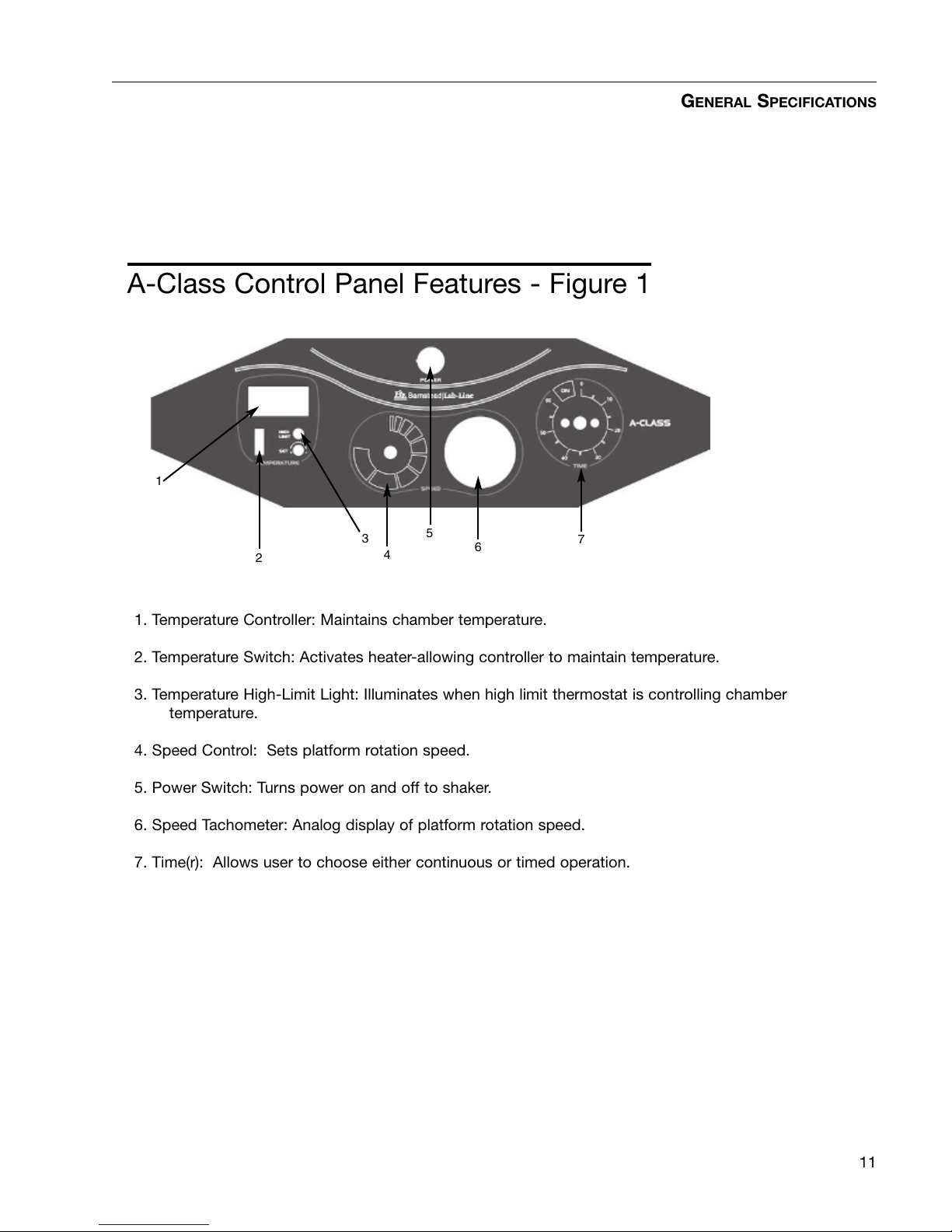
1. Temperature Controller: Maintains chamber temperature.
2. Temperature Switch: Activates heater-allowing controller to maintain temperature.
3. Temperature High-Limit Light: Illuminates when high limit thermostat is controlling chamber
temperature.
4. Speed Control: Sets platform rotation speed.
5. Power Switch: Turns power on and off to shaker.
6. Speed Tachometer: Analog display of platform rotation speed.
7. Time(r): Allows user to choose either continuous or timed operation.
11
GENERAL SPECIFICATIONS
A-Class Control Panel Features - Figure 1
1
2
3
4
5
67
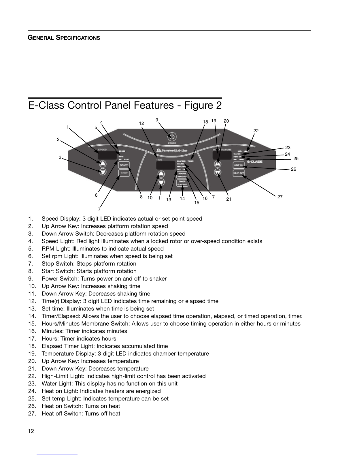
1. Speed Display: 3 digit LED indicates actual or set point speed
2. Up Arrow Key: Increases platform rotation speed
3. Down Arrow Switch: Decreases platform rotation speed
4. Speed Light: Red light Illuminates when a locked rotor or over-speed condition exists
5. RPM Light: Illuminates to indicate actual speed
6. Set rpm Light: Illuminates when speed is being set
7. Stop Switch: Stops platform rotation
8. Start Switch: Starts platform rotation
9. Power Switch: Turns power on and off to shaker
10. Up Arrow Key: Increases shaking time
11. Down Arrow Key: Decreases shaking time
12. Time(r) Display: 3 digit LED indicates time remaining or elapsed time
13. Set time: Illuminates when time is being set
14. Timer/Elapsed: Allows the user to choose elapsed time operation, elapsed, or timed operation, timer.
15. Hours/Minutes Membrane Switch: Allows user to choose timing operation in either hours or minutes
16. Minutes: Timer indicates minutes
17. Hours: Timer indicates hours
18. Elapsed Timer Light: Indicates accumulated time
19. Temperature Display: 3 digit LED indicates chamber temperature
20. Up Arrow Key: Increases temperature
21. Down Arrow Key: Decreases temperature
22. High-Limit Light: Indicates high-limit control has been activated
23. Water Light: This display has no function on this unit
24. Heat on Light: Indicates heaters are energized
25. Set temp Light: Indicates temperature can be set
26. Heat on Switch: Turns on heat
27. Heat off Switch: Turns off heat
12
GENERAL SPECIFICATIONS
1
2
3
4
5
7
68
9
E-Class Control Panel Features - Figure 2
10 11
12 18
17
16
13 15
14
19 20
21
22
23
24
25
26
27

Shipping Carton
This should be inspected upon delivery. When received,
carefully examine for any shipping damage before
unpacking. If damage is discovered, the delivering carri-
er should specify and sign for the damage on you copy
of the delivery receipt.
Open the carton carefully making certain that all parts are
accounted for before packaging materials are discarded.
After unpacking, if damage is found, promptly report it to
the carrier and request a damage inspection properly.
IMPORTANT: Failure to request an inspection of damage
within a few days after receipt of shipment absolves the
carrier from any liability for damage. You must call for a
damage inspection promptly.
Unpacking
Use the packing list below when unpacking to verify that
the complete unit has been received. Do not discard
packing materials until all is accounted for.
The following items are included in the shipment:
MaxQ 4000 shaker
Operator’s Manual- 057-287-00
Product Registration Card- 528-022-00
Inspection Tag- 528-028-00
Mounting Plate Mat- 790-316-11
Thumb Screw Knob (4) - 562-184-10
Male Connector (E-class only)- 420-359-00
If any items are missing, contact Barnstead International
at 1-800-553-0039.
Location
Put the shaker on a level table or bench capable of sup-
porting the weight of the shaker with any accessories
while in operation. Place shaker near an electrical outlet
that matches the unit nameplate requirements. Allow
approximately 2” (5 cm) of clearance around the unit for
free air convection, accessory attachments and user con-
venience. Shakers with refrigeration should be placed
near an accessible drain.
13
Unpacking and Installation
Electrical Requirements
SHKA4000 and SHKE4000 series shakers require a 120
VAC, 60 Hz power source. They are supplied with a 3-
wire line cord and should be plugged into an outlet
designed for 3-prong plugs. If an extension cord is used,
it also should be the 3-wire grounded type. For an outlet
designed to accept 2-prong plugs (ungrounded), it is
required that a qualified electrician replaces the outlet
with a new, grounded type.
SHKA4000-1CE and SHKE4000-1CE series shakers
require a 220-240 VAC, 50/60 Hz power source. They
are supplied with a Schuko cordset.
If a plug must be installed, use only the 3-prong ground-
ed type, rated for the unit load requirements and match-
ing the power outlet. Make sure the green ground wire is
secured to the plug ground terminal.
To eliminate hazard of electrical shock, make sure floor
around shaker is dry. In the event of accidental spilling
or splashing of liquids, clean up and/or neutralize the
spilled liquids before continuing.
Leave shaker disconnected when not in use.
14
UNPACKING AND INSTALLATION
Warning
Do not operate shaker with a dam-
aged electrical cord.
Platform Installation
1. Select the appropriate platform for the vessels
to be shaken. A wide variety of platforms and
accessories are available:
• Dedicated platforms have the maximum
number of flask clamps attached for safe oper-
ation.
• Combination platforms allow the user to
shake a wide variety of different sized vessels
on the same platform.
2. Carefully position the platform horizontally over
the shaker’s mounting plate, aligning the 4
mounting holes.
3. Position one of the thumbscrews provided
through each of the 4-platform mounting holes
and tighten securely.
Flask Clamp Installation
Each flask clamp contains a support spring located at
the narrow top of the clamp.
Depending on the size of the clamp, the clamp base may
contain one or several screws necessary to secure the
clamp to the platform. All screws provided with the
clamp must be properly attached to the platform.
1. Carefully place the desired vessel in the clamp
by first pulling the clamp spring far enough
apart to enable the flask base to be positioned
inside the clamp. Gently slide the flask into its
proper position securing it to the wider bottom
of the clamp. The spring will hold the neck of
the flask securely in place and provide security
during shaking.
2. Make sure all vessels are securely clamped
before turning on unit.
Wherever possible, vessels should contain a stopper to
prevent hazardous substances being thrown out during
the mixing action.
15
UNPACKING AND INSTALLATION
Caution
Do not operate shaker with an
unbalanced load. Platforms should
be loaded for optimum stability and
operation. Do not lift shaker by the
platform.
Warning
Do not operate the shaker at
speeds that will cause the contents
of vessels to be thrown out.
Test Tube Rack Installation
1. Position the test tube rack on the combination
platform so that the cutouts on the rack’s out-
side bottom are aligned with corresponding
mounting holes on the platform. There are two
cutouts on each side of the rack.
2. Secure the rack to the platform with mounting
screws provided with the rack.
16
UNPACKING AND INSTALLATION
A-Class
Please refer to page 11 for control panel reference.
Power Switch
1. Depress top portion of power switch to turn on
shaker.
2. Depress bottom portion of power switch to turn
off shaker.
Speed Control and Display
1. Slowly rotate the knob on the solid-state speed
control clockwise to increase speed and coun-
terclockwise to decrease speed. The markings
on the outside of the dial are for reference pur-
poses only.
2. The speed control tachometer provides an ana-
log readout of the actual platform rotation
speed up to a maximum of 400 rpm.
Time(r)
1. From the 12 o’clock off position, rotate timer
knob counterclockwise to the ON position to
initiate continuous operation.
2. For timed operation, rotate timer knob clock-
wise from 1 minute to 60 minutes. The mark-
ings on the side of the dial are in 5-minute
increments.
17
Operation
Caution
It is recommended that shaking
action be started at a low speed in
order to check that all vessels are
secure and that no spilling of
contents will occur.
Note
Shaker will not operate if the timer
is in the off position.

Temperature Controller-Setting Temperature
Please refer to Figure 3 for control panel reference.
1. CONTROLLER SELF-TEST: When the shaker is
powered up, the controller will display 8888 along
with the three decimal points and the HEAT ON
indicator lamp. The display will then blank out for 2
seconds before showing the chamber temperature.
2. HEAT ON INDICATOR: The HEAT ON indicator
lamp is lit when the chamber heaters are receiving
power. The lamp will normally flash when the
chamber temperature is at set point.
3. SET POINT ADJUSTMENTS: The temperature con-
troller normally displays the chamber temperature.
To view or change the temperature set point pro-
ceed as follows:
A. Press and hold the “star” (✳) key and use either
the up or down arrow key to adjust the set point to
the desired temperature. Release the “star” (✳)
key.
B. Allow sufficient time for chamber temperature to
stabilize.
Temperature Calibration
1. Fill a 250-ml Erlenmeyer flask with approximately
100 ml of water and position it at the approximate
geometric center of the shaking platform.
2. Install a thermocouple inside the flask with the ther-
mocouple junction in direct contact with the water.
18
OPERATION
Press Controller
✳View set point
✳ Decrease set point
✳ Increase set point
Figure 3: Temperature Controller
3. Press and hold the “star” (✳) key and using the
up or down arrow key, adjust the set point to
the desired temperature.
4. Allow the shaker to run until chamber tempera-
ture has stabilized.
5. The controller display should now be indicating
the set point temperature. Make note of the
thermometer reading.
6. Press and hold both arrow keys until the con-
troller display indicates “tunE”. Release the
arrow keys. Press and release the down arrow
key, the display should now alternate between
“LEUL” and “1”. Press and hold the “star” (✳)
key and using the up arrow key adjust the dis-
play to read “3”. Release the “star” (✳) key. The
display should now alternate between “LEUL”
and “3”. Press and release the up arrow key
until the display indicates “Zero”. The display
should now alternate between “Zero” and a
numerical value.
7. Using the examples shown in Figure 4 and the
thermometer value obtained in step 5 above,
enter the correct “Zero” value into the controller
by pressing the “star” (✳) key and using the up
or down arrow key. If there is already a “Zero”
value present then add the new value to the
one already present.
8. When the correct “Zero” value has been
entered, press and hold the two arrow keys
together until the display again indicates the
chamber temperature. If the procedure was
done correctly, the controller display should
now agree with the thermometer reading to
within ±0.5°C.
9. Allow the unit to run for at least an additional 30
minutes.
10. Re-check the thermometer reading. The con-
troller display and the thermometer should
agree to within ±0.5°C. If not repeat steps 6, 7
and 8.
19
OPERATION
Thermometer = 60 °C
Controller Reading = 65 °C
Subtract = -5 °C
Enter Zero value of -5 °C
Thermometer = 70 °C
Controller Reading = 65 °C
Subtract = +5 °C
Enter Zero value of +5 °C
Figure 4: Determining Zero Value
E-Class
Please refer to page 12 for control panel reference.
Turning Shaker On
Beginning with the shaker power off.
1. Press membrane power switch once (I) to turn
on shaker.
2. Press membrane power switch a second time
(O) to turn off shaker.
Setting Shaking Speed
1. Hold down appropriate arrow membrane switch
in the speed module of the control panel, up or
down, until desired speed is set up to 500 rpm.
SET RPM light will illuminate.
2. Press START membrane switch to begin shak-
ing. RPM light will illuminate.
3. Press STOP membrane switch to end shaking.
SET RPM light will illuminate.
Calibrating Shaking Speed
1. Choose a speed for which calibration is desired
by using the shaker’s up or down arrow keys.
2. Measure current shaker speed by using a digital
hand held tachometer.
3. If the tachometer reading matches the shaker
display, no calibration is necessary. If the
tachometer reading is different from the shak-
er’s display, then calibration is required.
4. To get into the calibration mode, hold down the
START key, press and release the STOP key,
then release the START key.
20
OPERATION
Note
There will be a 3 second delay from
the time power is turned on to the
time the shaker is activated.
Control panel will illuminate when
shaker power is activated. There
will be an audible beep before the
display lights up.
Note
Speed can be changed without
pressing the start or stop membrane
switches. Simply press the appro-
priate up or down membrane switch
until desired rpm is reached. There
will be an audible beep before the
display lights.
This manual suits for next models
12
Table of contents


