manuals.online logo
Brands
  1. Home
  2. •
  3. Brands
  4. •
  5. Graco
  6. •
  7. Paint Sprayer
  8. •
  9. Graco C Series Operation manual

Graco C Series Operation manual

307–237
Rev. M
Supercedes L
INSTRUCTIONS-PARTS
LIST
INSTRUCTIONS
This
manual contains important
warnings and information.
READ AND KEEP FOR REFERENCE.
AUTOMATIC
AIR
SPRA
Y GUN
STAINLESS STEEL FLUID PASSAGES
100 psi (7 bar) Maximum Working Pressure
Model 210–744, Series C
Basic
gun without needle, nozzle, or air cap
With basic gun 210–744, order the needle-
nozzle kit and air cap you want separately
. See
page 8 for available kits and air caps.
COMPLETE GUNS*
Model 208–603
With
0.042” nozzle; 0.033” needle;
for light viscosity fluids
Model 208–604
With
0.055” nozzle; 0.046” needle;
for medium viscosity fluids
Model 208–605
With
0.070” nozzle; 0.061” needle;
for heavy viscosity fluids
* When ordering complete guns, order the
model number and specify the air cap you want.
See page 5 for available air caps.

GRACO INC. P.O. BOX 1441
MINNEAPOLIS, MN
55440–1441
COPYRIGHT
1976, GRACO INC.
Graco
Inc. is registered to I.S. EN ISO 9001

Table
of Contents
Warnings 2.
. . . . . . . . . . . . . . . . . . . . . . . . . . . . . . . . . . . . .
Ordering
Charts
5.
. . . . . . . . . . . . . . . . . . . . . . . . . . . . . . .
Installation 6
. . . . . . . . . . . . . . . . . . . . . . . . . . . . . . . . . . . .
Operation 8
. . . . . . . . . . . . . . . . . . . . . . . . . . . . . . . . . . . . .
Maintenance 9
. . . . . . . . . . . . . . . . . . . . . . . . . . . . . . . . . . .
Troubleshooting 9
. . . . . . . . . . . . . . . . . . . . . . . . . . . . . . . .
Service 11
. . . . . . . . . . . . . . . . . . . . . . . . . . . . . . . . . . . . . .
Parts 12
. . . . . . . . . . . . . . . . . . . . . . . . . . . . . . . . . . . . . . . .
Dimensional
Drawing
13.
. . . . . . . . . . . . . . . . . . . . . . . . .
Warranty 16
. . . . . . . . . . . . . . . . . . . . . . . . . . . . . . . . . . . . .
Graco
Phone Number
16.
. . . . . . . . . . . . . . . . . . . . . . . . .
Symbols
Warning Symbol
WARNING
This
symbol alerts you to the possibility of serious
injury or death if you do not follow the instructions.
Caution Symbol

This
symbol alerts you to the possibility of damage to
or destruction of equipment if you do not follow the
instructions.


EQUIPMENT MISUSE HAZARD
Equipment
misuse can cause the equipment to rupture or malfunction and result in serious injury
.
D
This equipment is for professional use only
.
D
Read all instruction manuals, tags, and labels before operating the equipment.
D
Use the equipment only for its intended purpose. If you are not sure, call your Graco distributor
.
D
Do not alter or modify this equipment. Use only genuine Graco parts and accessories.
D
Check equipment daily
. Repair or replace worn or damaged parts immediately
.
D
Do not exceed the maximum working pressure stated on the equipment or in the
T
echnical Data
for your equipment. Do not exceed the maximum working pressure of the lowest rated component
in your system.
D
Use fluids and solvents which are compatible with the equipment wetted parts. Refer to the
Tech-
nical Data
section of all equipment manuals. Read the fluid and solvent manufacturer
’
s warnings.
D
Handle hoses carefully
. Do not use hoses to pull equipment.
D
Route hoses away from traffic areas, sharp edges, moving parts, and hot surfaces. Do not expose
Graco hoses to temperatures above 82
_
C (180
_
F) or below –40
_
C (–40
_F).
DW
ear hearing protection when operating this equipment.
D
Comply with all applicable local, state, and national fire, electrical, and safety regulations.



PRESSURIZED EQUIPMENT HAZARD
Spray
from the gun, hose leaks, or ruptured components can splash fluid in the eyes or on the skin
and cause serious injury
.
D
Do not stop or deflect leaks with your hand, body
, glove or rag.
D
Follow the
Pressure Relief Procedure
on page 8 whenever you: are instructed to relieve the
pressure; stop spraying; clean, check, or service the equipment; or install or clean the fluid nozzle.
DT
ighten all fluid connections before operating the equipment
D
Check the hoses, tubes, and couplings daily
. Replace worn, damaged, or loose parts immediately
.
Permanently coupled hoses cannot be repaired; replace the entire hose.
FIRE AND EXPLOSION HAZARD
Improper
grounding, poor ventilation, open flames or sparks can cause a hazardous condition and
result in a fire or explosion and serious injury
.
D
Ground the equipment and the object being sprayed.
D
If there is any static sparking or you feel an electric shock while using this equipment,
stop spray-
ing immediately
.
Do not use the equipment until you identify and correct the problem.
D
Provide fresh air ventilation to avoid the buildup of flammable fumes from solvents or the fluid
being sprayed.
D
Keep the spray area free of debris, including solvent, rags, and gasoline.
D
Before operating this equipment, electrically disconnect all equipment in the spray area.
D
Before operating this equipment, extinguish all open flames or pilot lights in the spray area.
D
Do not smoke in the spray area.
D
Do not turn on or of
f any light switch in the spray area while operating or if fumes are present.
D
Do not operate a gasoline engine in the spray area.
TOXIC FLUID HAZARD
Hazardous
fluid or toxic fumes can cause serious injury or death if splashed in the eyes or on the skin,
inhaled, or swallowed.
D
Know the specific hazards of the fluid you are using.
D
Store hazardous fluid in an approved container
. Dispose of hazardous fluid according to all local,
state and national guidelines.
D
Always wear protective eyewear
, gloves, clothing and respirator as recommended by the fluid and
solvent manufacturer
.

Notes


Ordering
Charts
External Mix Air Caps
With
NEEDLE-
NOZZLE KITS, use
(See Note Below)
AIR
CAPS TYPE
FEED
***
AIR CONSUMPTION
SPRAY
PATTERN*
at 8
”
(S
ee
N
o
t
e
B
e
l
ow
)
***
30 psi (2 bar)
50 psi (3.5 bar)
70 psi (5 bar)
a
t
8”
(200 mm)
THIN FLUIDS:
5–14 Seconds (No. 4 Ford Cup), 16–20 Seconds (No. 2 Zahn Cup), 10–30 cps;
stains,
solvents, sealers, lacquers, primers, zinc chromates, acrylics, water
, and similar fluids.
Kit
No. 208–606
0.042”
(1.07
mm) dia. nozzle
0.033”
(0.84 mm) dia. needle
106–940
106–945
106–943
106–942
106–950
P
P
P
P
P
6.0
cfm (0.17 m
#/min)
9.0 cfm (0.25 m
#/min)
9.0 cfm (0.25 m
#/min)
1
1.0 cfm (0.31 m
#/min)
12.0 cfm (0.34 m
#/min)
9.0 cfm (0.25 m
#/min)
14.0 cfm (0.40 m
#/min)
14.0 cfm (0.40 m
#/min)
14.0 cfm (0.40 m
#/min)
18.0 cfm (0.51 m
#/min)
1
1.0 cfm (0.31 m
#/min)
19.0 cfm (0.54 m
#/min)
19.0 cfm (0.54 m
#/min)
19.0 cfm (0.54 m
#/min)
23.0 cfm (0.65 m
#/min)
9” (230 mm)
9” (230 mm)
15” (380 mm)
13” (330 mm)
12” (300 mm)
MEDIUM
FLUIDS:
16–18 Seconds (No. 4 Ford Cup), 20–30 Seconds (No. 2 Zahn Cup), 30–70 cps;
lac-
quers, varnishes, urethanes, primers, epoxies, shellacs, synthetic enamels, light adhe
-
sives, and similar fluids.
Kit
No. 208–660
0.042”
(1.07
mm) dia. nozzle
0.033”
(0.84 mm) dia. needle
106–940
106–945
106–943
106–942
106–950
P
P
P
P
P
6.0
cfm (0.17 m
#/min)
9.0 cfm (0.25 m
#/min)
9.0 cfm (0.25 m
#/min)
1
1.0 cfm (0.31 m
#/min)
12.0 cfm (0.34 m
#/min)
9.0 cfm (0.25 m
#/min)
14.0 cfm (0.40 m
#/min)
14.0 cfm (0.40 m
#/min)
14.0 cfm (0.40 m
#/min)
18.0 cfm (0.51 m
#/min)
1
1.0 cfm (0.31 m
#/min)
19.0 cfm (0.54 m
#/min)
19.0 cfm (0.54 m
#/min)
19.0 cfm (0.54 m
#/min)
23.0 cfm (0.65 m
#/min)
9” (230 mm)
9” (230 mm)
15” (380 mm)
13” (330 mm)
12” (300 mm)
Kit No. 208–607
0.055”
(1.40
mm) dia. nozzle
0.046
(1.17 mm) dia. needle
106–945
106–943
106–942
106–944
106–950
P
P
P
P
P
9.0 cfm (0.25 m
#/min)
9.0 cfm (0.25 m
#/min)
1
1.0 cfm (0.31 m
#/min)
1
1.0 cfm (0.31 m
#/min)
12.0 cfm (0.34 m
#/min)
14.0 cfm (0.40 m
#/min)
14.0 cfm (0.40 m
#/min)
14.0 cfm (0.40 m
#/min)
18.0 cfm (0.51 m
#/min)
18.0 cfm (0.51 m
#/min)
19.0 cfm (0.54 m
#/min)
19.0 cfm (0.54 m
#/min)
19.0 cfm (0.54 m
#/min)
24.0 cfm (0.68 m
#/min)
23.0 cfm (0.65 m
#/min)
9” (230 mm)
15” (380 mm)
13” (330 mm)
12” (300 mm)
12” (300 mm)
Kit No. 208–608
0.070”
(1.78
mm) dia. nozzle
0.061”
(1.55 mm) dia. needle
106–948
106–950 P
P4.0
cfm (0.1
1 m
#/min)
12.0 cfm (0.34 m
#/min)
5.0 cfm (0.14 m
#/min)
18.0 cfm (0.51 m
#/min)
7.0 cfm (0.20 m
#/min)
23.0 cfm (0.65 m
#/min)
6” (150 mm)
12
“ (300 mm)
HEAVY
FLUIDS:
Over 28 Seconds (No. 4 Ford Cup), 30 Seconds (No. 2 Zahn Cup), 70 cps;
acrylic,
epoxies, vinyls, house paint, block sealers, mill whites, red lead, wood filler
, and similar
fluids.
Kit
No. 208–607
0.055”
(1.40
mm) dia. nozzle
0.046
(1.17 mm) dia. needle
106–945
106–943
106–942
P
P
P
9.0 cfm (0.25 m
#/min)
9.0 cfm (0.25 m
#/min)
1
1.0 cfm (0.31 m
#/min)
14.0 cfm (0.40 m
#/min)
14.0 cfm (0.40 m
#/min)
14.0 cfm (0.40 m
#/min)
19.0 cfm (0.54 m
#/min)
19.0 cfm (0.54 m
#/min)
19.0 cfm (0.54 m
#/min)
9” (230 mm)
15” (380 mm)
13” (330 mm)
Kit No. 208–608
0.070”
(1.78
mm) dia. nozzle
0.061”
(1.55 mm) dia. needle
106–943
106–942 P
P9.0
cfm (0.25 m
#/min)
1
1.0 cfm (0.31 m
#/min)
14.0 cfm (0.40 m
#/min)
14.0 cfm (0.40 m
#/min)
19.0 cfm (0.54 m
#/min)
19.0 cfm (0.54 m
#/min)
15” (380 mm)
13” (330 mm)
HEAVY
FLUIDS:
Heavy adhesives and mastics
Kit
No. 208–608
0.070”
(1.78
mm) dia. nozzle
0.061”
(1.55 mm) dia. needle
106–946 P13.0
cfm (0.37 m
#/min)
19.0 cfm (0.54 m
#/min)
25.0 cfm (0.71 m
#/min)
24” (610 mm)
*
Spray Patterns determined spraying 50 cps enamel at 60 psi (4 bar) air pressure, with 10 psi (0.7 bar) fluid pressure.
** Includes ring.
*** “P” = Pressure
NOTE:
When selecting air caps for use with complete
gun models, select from air caps recommended for
use with needle-nozzle kits having the same size
needle and nozzle as the gun.
For complete gun:
Choose from caps
recommended for:
Model
208–603
Model 208–604
Model 208–605
Kit No. 208–606
Kit No. 208–607
Kit No. 208–608
Needle-Nozzle Conversion Kits (Must be ordered separately)
Includes
matched needle and nozzle, and nozzle gasket (103–464)
Type of Fluid
Kit No.
Nozzle Needle
yp
Orifice
Size
Part No.
Probe Dia.
Part No.
Light V
iscosity
Medium V
iscosity
Heavy V
iscosity
208–606
208–607
208–608
0.042”
0.055”
0.070”
(176–800)
(176–801)
(176–802)
0.033”
0.046”
0.061”
(170–245)
(170–246)
(170–247)

Installation
Fig.
1
J
K
L
HA
E
DG
C
FBM
KEY
A
B
C
D
E
F
G
H
J
K
L
M
Automatic Air Spray Gun
Fluid Line
Air Filter
3-W
ay Air Solenoid
Cylinder Air Supply Line
Atomizing Air Supply Line
Air Regulator
Sensing Device
Conveyor
Pump
Fluid Supply
Fluid Pressure Regulator
The illustration shown above is only a guide to the
equipment needed for an automatic spraying system.
For design assistance, contact your Graco representa
-
tive.
WARNING
T
OXIC FLUID HAZARD
T
o prevent hazardous concentrations of
toxic and/or flammable vapors, spray
only in a properly ventilated spray booth.
Never operate the spray gun unless ventilation
fans are operating.
Check and follow all of the national, state, and local
codes regarding air exhaust velocity requirements.
Check and follow all local safety and fire codes.
NOTE:
The reference numbers and letters in paren
-
theses in the text refer to the callouts in the drawings.
1.
Mount the gun (A) on a 0.50 in. (12 mm) diameter
rod mounting fixture which allows you to adjust
the spray pattern direction and the gun’
s distance
from the work.
2.
Blow out the fluid lines (B) with air
, then flush with
solvent to remove dirt and contaminants before
connecting to the system.
3.
Be sure the compressed air supply is clean and
dry
. Install an air filter (C) to remove harmful dirt
and moisture, which can af
fect the appearance of
your finished workpiece.
4.
Install a normally closed, 3-way air solenoid
valve (D) in the cylinder air supply line (E). Con
-
nect an air hose from the solenoid valve to the
gun’
s 1/4 npsm(m) cylinder air inlet.
5.
Connect an atomizing air supply line (F) to the
gun’
s 1/4 npsm atomizing air inlet.
6.
Use separate air regulators (G) to control atomiz
-
ing air and cylinder air
.
7.
Connect a fluid hose (B) to the gun’
s 3/8 npsm
fluid inlet.


Installation
Recommended Hose Sizes
(General
Purpose)
Fluid Hose Air Hose
Length
Needed
ID Length Needed ID
0–35 ft.
(0–11 m)
3/8 in.
0–100 ft.
(0–30 m) 5/16
in.
35–100 ft.
(11–30 m)
1/2 in.
100–200 ft.
(30–60 m)
3/8 in.
100–200 ft.
(30–60 m)
3/4 in.
()
Adjust the system’
s sensing device (H) so that the gun
starts spraying just before meeting the workpiece and
stops just after the piece has passed. See Fig. 1.
The gun requires a minimum of 40 psi (3 bar) air
pressure to the cylinder
. The atomizing air pressure is
generally 43 to 57 psi (3 to 4 bar). The fluid pressure
supply is normally 10 to 15 psi (0.7 to 1.0 bar).
The external inlet threads of this gun are a combina
-
tion American NPSM and British Whitworth pipe thread
to allow coupling either type of female swivel union.

Operation
Pressure Relief Procedure

PRESSURIZED
EQUIPMENT HAZARD
The system pressure must be manually
relieved to prevent the system from
starting or spraying accidentally
. Fluid
under high pressure can be injected through the
skin and cause serious injury
. T
o reduce the risk of
an injury from injection, splashing fluid, or moving
parts, follow the
Pressure Relief Procedure
whenever you:
D
are instructed to relieve the pressure,
D
stop spraying,
D
check or service any of the system equipment,
D
or install or clean the spray tip.
1. T
urn of
f the air and fluid supply to the gun.
2. T
rigger the gun into a grounded metal waste
container to relieve system pressures.
Filter the Fluid
Strain
or filter the paint to remove coarse particles and
sediment, then check the viscosity of your paint. Refer
to page 5 for the proper viscosity
.
Install the air cap (38). See Fig. 2.
The direction of the spray pattern is controlled by the
position of the air cap. The horns of the air cap should
be the opposite direction (horizontal or vertical) of the
desired direction of the spray pattern. T
o change the
spray pattern, first
relieve the pressure, then loosen
and turn the air cap to the desired position, and hand
tighten the air cap (38) securely
.
Adjusting the Spray Pattern
To
minimize overspray
, adjust the pattern for each part
being coated.
For maximum flow
, leave the fluid adjusting knob (18)
in the full open position. See Fig. 2.
The air adjusting screw (33) controls the pattern
shape, the fluid adjusting screw (18) controls the
volume of the fluid output, and the atomizing air regu
-
lator controls the degree of atomization.
Adjust the Pattern Size
T
urn the air adjusting screw (33) out (counterclock
-
wise) to make the spray pattern wider and flat, or in
(clockwise) to decrease to a round pattern.
Adjust the Fluid Output or Pressure Feed
T
urn the fluid adjusting screw (18) out all the way
(counterclockwise). Then adjust the air pressure at the
fluid supply until the desired flow is obtained. For the
final adjustment, turn the fluid adjusting valve in (clock
-
wise) to reduce the volume of fluid output to obtain the
desired results
NOTE:
If the fluid adjusting valve is turned in all the
way
, the gun will emit only air
.
T
est Spray Pattern
Hold the gun about 10 in. (254 mm) away from the
surface of the test piece. Adjust the air pressure to the
gun until proper atomization is achieved. Always use
the lowest possible atomizing air pressure to obtain the
desired results.
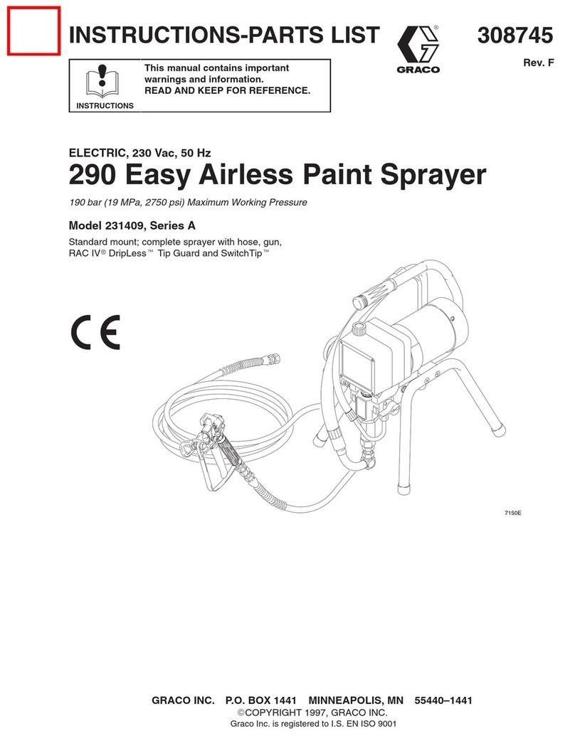
Normal Spray Pattern
Proper adjustment will give a spray
pattern shaped like this.
See
Troubleshooting Chart
on page 10 for the cause
and solution of improper spray patterns.


Maintenance
Cleaning
CAUTION
T
o ensure thorough flushing, and to avoid gun dam
-
age, be sure that any solvent you use is compatible
with the fluid being sprayed and the wetted parts of
the gun.
Never immerse the gun in solvent. Prolonged expo
-
sure to solvent damages the packings.
WARNING
T
o reduce the risk of serious injury
, whenever you
are instructed to relieve pressure, always follow the
Pressure Relief Procedure
on page 8.
1.
Flush the gun with a compatible solvent until all
traces of paint are removed from the gun pas
-
sages.
2.
Relieve the pressure
3.
Wipe the outside of the gun clean with a solvent
dampened cloth.
4.
If the air cap (38) needs cleaning, relieve the
pressure
, and remove it from the gun. Soak the
air cap in solvent and scrub with a fine bristled
brush. T
o clean the holes in the air cap, use a
toothpick or other soft implement to avoid damag
-
ing critical surfaces.
CAUTION
T
o avoid scratches which can distort the spray
pattern, never use metal instruments to clean holes
in the air cap or fluid nozzle.
Lubrication
Lubricate the exposed portion of the fluid needle (37)
daily with lightweight grease or petroleum jelly
.
Troubleshooting
WARNING
T
o reduce the risk of serious injury
, whenever you
are instructed to relieve pressure, always follow the
Pressure Relief Procedure
on page 8.
1.
Relieve the pressure before you check or service
any system equipment.
2.
Check all possible causes and solutions in the
Troubleshooting Charts
before disassembling
the gun.
Gun Operation Troubleshooting Chart
Problem Cause Solution
Fluid
packing nut leaking
Loose needle packing nut (12, 13).
W
orn packing (8, 23)
Tighten.
Replace packing.
Air leakage from front of gun
Air piston (25) and packings
(2, 4, 5, 6, 7) not seating properly
.
Clean, service.
Fluid leakage from front of gun
Needle (37) worn or damaged.
W
orn needle and seat in fluid
nozzle (36).
Needle packing nut (12, 13) too tight.
Replace needle and nozzle as a set.
Lubricate and adjust.

Troubleshooting
Spray Pattern Troubleshooting Chart
Problem:
Improper
Spray Pattern
Cause Solution
Fluttering or spitting spray
Insuf
ficient fluid in the supply con
-
tainer.
Dry or worn fluid needle packing,
or loose packing nut permits air
into fluid passage.
Loose fluid nozzle, or damaged
fluid nozzle taper seat.
Dirt between fluid nozzle, taper
seat and body
.
Loose or cracked fluid inlet fitting.
Loose fluid tube in pump or tank.
Fill supply container
Lubricate, or replace packings (8,
23); tighten packing nuts (12, 13)
T
ighten, or replace needle and
nozzle.
Clean.
T
ighten, or replace housing (24).
Tighten.
Fluid build-up on air cap; partially
clogged horn holes. Full air pres
-
sure from clean horn hole forces
fan pattern toward clogged end.
Damaged fluid nozzle or air cap
holes.
Clean with soft implement or sub
-
merge in suitable solvent and wipe
clean.
Replace damaged part.
Fluid build-up on the perimeter of
fluid nozzle orifice, or partially
clogged fluid nozzle orifice.
Remove obstruction.
Never
use
wire or hard instruments.
T
oo high atomization air pressure.
Fluid too thin.
Not enough fluid pressure.
Reduce air pressure, or adjust air
adjusting screw (27).
Regulate fluid viscosity
.
Increase fluid pressure
.
Low atomization air pressure.
Fluid too thick.
T
oo much fluid.
Increase air pressure or adjust air
adjusting screw (27).
Regulate fluid viscosity
.
Reduce fluid pressure.
Adjust fluid adjustment knob (6)
until proper pattern is obtained.
Streaks
Last coat of fluid applied too wet.
T
oo much air pressure.
Insuf
ficient air pressure.
Non-uniform spray pattern
.
Apply drier finish with multiple
strokes.
Use lowest air pressure neces
-
sary.
Increase air pressure.
Clean or replace air cap (38).


Service
Fig. 2 06359
25†
18
33
22
13
26
23†
10
37
36
38
Air
V
alve Service
Note:
Repair kit 208–609 is available. Use all the parts
in the kit for the best results. Kit parts are designated
with a dagger
, for example (8†).
Note:
Always replace fluid nozzle gasket (35) when
replacing fluid nozzle. See the parts drawing on
page 12.
WARNING
T
o reduce the risk of serious injury
, whenever you
are instructed to relieve pressure, always follow the
Pressure Relief Procedure
on page 8.
1.
Relieve the pressure
2.
If there is air leakage at the packing nut (12),
tighten the nut. See the parts drawing on page 12.
3.
If leakage continues, replace the packings (8†)
Fluid Packing Replacement
1. Relieve
the pressure
2.
If fluid leakage occurs at the packing nut (13),
tighten the nut. If leakage continues, replace the
packing (23†).
3.
Loosen the packing nuts (12 & 13). Disassemble
the air piston and cylinder
, and remove the needle
(37).
4.
Remove the packing nuts and packings from the
cavities, then clean and inspect all parts for wear
or damage. Replace parts as necessary
.
5.
Lubricate the packings with lightweight oil or Graco
Throat Seal Liquid, and insert the packings into the
cavities. Install the needle (37) and piston (25†) in
the gun body
. Slide the packing nuts onto the
needle before inserting the needle into the fluid
packing cavity
.
6.
Push the needle and the piston fully forward, and
turn the adjusting nut (17) all the way into position.
T
urn the adjusting nut two turns counterclockwise.
T
ighten the locknut (16) to hold the adjustment.
7.
With the needle (37) in place, screw the fluid
packing nut (13) in until the packing (23†) is fully
compressed, then back off until free needle move
-
ment is attained. Reassemble the remainder of the
gun in reverse order of disassembly
.
For best packing life, lubricate the gun daily as ex
-
plained in
Maintenance.

Parts
05671
37
16 17
20
21
19
918
33
†28
31
29
24
26
*35
36
38
10
*34
*11 3
14*
23† 13
12 8†
6† 5†
4† 22 2**
†7
†25
Ref.
No. 1
Bare Gun
Includes items 2–34
Ref. No. 27
Air Adjusting Screw Assy
.
Includes items 28–33
1
3
2
11
1
2
3
4
4
T
orque to 20–25 ft-lb (27–37 N
Sm)
T
orque to 15–20 ft-lb (20–27 N
Sm)
T
orque to 9–1
1 ft-lb (10–15 N
Sm)
T
orque to 40–45 ft-lb (54–61 N
Sm)
5
6
7
1/4 npsm (Cylinder Air Inlet)
5
1/4 npsm (Atomizing Air Inlet)
6
3/8 npsm Fluid Inlet
7
Complete Gun Includes:
Needle (Ref. No. 37)
Nozzle (Ref. No. 36)
Model 208–603
Model 208–604
Model 208–605
170–245 (0.033”)
170–246 (0.046”)
170–247(0.061”)
176–800 (0.042”)
176–801 (0.055”)
176–802 (0.070”)


Parts
Ref.
No. Part No. Description Qty.
1 210–744 AUTOMATIC AIR SPRAY GUN; bare
Series C
Includes items 2–34
1
2† 103–338 PACKING, o-ring; VitonR1
3 103–522 SCREW
, sq hd set; 3/8”–16 x 5/8”
1
4† 103–523 GASKET, copper asbestos 1
5† 103–524 GASKET, copper asbestos 1
6† 103–610 PACKING, o-ring; VitonR1
7† 103–649 PACKING, o-ring; VitonR1
8† 160–240 PACKING, v-block; leather 2
9 162–782 LOCKNUT 1
10 106–914 RING, air cap 1
11* 106–916 STUD, coupler
’ 3/8” npsm
1
12* 171–333 NUT
, packing; fluid needle
1
13 171–332 NUT
, packing; fluid needle
1
14* 106–917
ADAPTER, air inlet; 1/4–18–6
2
16 170–242 NUT, lock 1
17 170–243 NUT
, needle adjusting
1
18 170–244 SCREW
, needle adjusting
1
19 170–249 CYLINDER, air piston 1
20 724–391 SPRING, compression; 2.0”
(51 mm) long
1
21 170–253 SPRING compression; 1.375”
(35 mm) long
1
22 171–722 HOUSING, valve 1
Ref.
No. Part No. Description Qty.
23† 106–901 P
ACKING, needle
1
24 210–743 HOUSING, valve 1
25† 208–718 PISTON, air 1
26 106–913
BAFFLE, air
1
27 106–121 AIR ADJUSTING SCREW ASSY.
Includes items 28–33
1
28† 168–110 P
ACKING, o–ring; V
itonR1
29 105–456
RING, retaining
1
31 176–773 HOUSING, spring 1
32 169–883 W
ASHER, flat; steel
1
33 217–020 SCREW
, air adjusting
1
34* 106–900 GASKET
, T
eflonR1
35* 108–784 GASKET
, fluid nozzle; copper with
mineral board insert
1
36
–
NOZZLE; see chart on page 5
1
37
–
NEEDLE; see chart on page 5
1
38
–
AIR CAP; see chart on page 5
1
*
Recommended “tool box” spare parts. Keep on hand to
reduce down time.
†
These parts are included in Repair Kit 208–609, which
may be purchased separately
.
Viton
R
and T
eflon
R
are registered trademarks of the Du Pont
Company.
Dimensions
05673
1.81”
(46.0 mm)
2.50” (63.6 mm)
3.69” (93.7 mm)
3.69” (93.7 mm)
7.56” (192.1 mm) max.
0.69” (17.5 mm)
0.50” (12.7 mm) DIA MOUNTING HOLE
1/4 NPSM AIR INLETS
MAX. WIDTH: 1.94” (49.2 mm)
3/8
NPSM
FLUID
INLET

Notes


Notes

The
Graco Warranty and Disclaimers
WARRANTY
Graco
warrants all equipment listed in this manual which is manufactured by Graco and bearing its name to be free from defects
in material and workmanship on the date of sale by an authorized Graco distributor to the original purchaser for use. Graco will,
for a period of twelve months from the date of sale, repair or replace any part of the equipment determined by Graco to be defec
-
tive. This warranty applies only when the equipment is installed, operated and maintained in accordance with Graco’
s written rec-
ommendations.
This warranty does not cover
, and Graco shall not be liable for general wear and tear
, or any malfunction, damage or wear
caused by faulty installation, misapplication, abrasion, corrosion, inadequate or improper maintenance, negligence, accident,
tampering, or substitution of non-Graco component parts. Nor shall Graco be liable for malfunction, damage or wear caused by
the incompatibility of Graco equipment with structures, accessories, equipment or materials not supplied by Graco, or the im
-
proper design, manufacture, installation, operation or maintenance of structures, accessories, equipment or materials not sup
-
plied by Graco.
This warranty is conditioned upon the prepaid return of the equipment claimed to be defective to an authorized Graco distributor
for verification of the claimed defect. If the claimed defect is verified, Graco will repair or replace free of charge any defective
parts. The equipment will be returned to the original purchaser transportation prepaid. If inspection of the equipment does not
disclose any defect in material or workmanship, repairs will be made at a reasonable charge, which charges may include the
costs of parts, labor
, and transportation.
THIS WARRANTY IS EXCLUSIVE, AND IS IN LIEU OF ANY OTHER WARRANTIES, EXPRESS OR IMPLIED,
INCLUDING
BUT NOT LIMITED TO WARRANTY OF MERCHANTABILITY OR WARRANTY OF FITNESS FOR A PARTICULAR PUR-
POSE.
Graco’
s sole obligation and buyer
’
s sole remedy for any breach of warranty shall be as set forth above. The buyer agrees that no
other
remedy (including, but not limited
to, incidental or consequential damages for lost profits, lost sales, injury to person or prop
-
erty
, or any other incidental or consequential loss) shall be available. Any action for breach of warranty must be brought within two
(2)
years of the date of sale.
GRACO MAKES NO WARRANTY, AND DISCLAIMS ALL IMPLIED WARRANTIES OF MERCHANTABILITY AND FITNESS
FOR A PARTICULAR PURPOSE IN CONNECTION WITH
ACCESSORIES, EQUIPMENT
, MA
TERIALS, OR COMPONENTS
SOLD BUT NOT MANUFACTURED BY GRACO.
These items sold, but not manufactured by Graco (such as electric motors,
switches, hose, etc.) are subject to the warranty
, if any
, of their manufacturer
. Graco will provide purchaser with reasonable assis
-
tance in making any claim for breach of these warranties.
For Sales to Canadian Customers:
Except
as expressly stated herein, Graco makers no representations, warranties
or conditions, express, implied or collateral, con
-
cerning
any goods or services sold, and
GRACO SHALL NOT BE LIABLE IN ANY MANNER FOR
any other representation,
warranty
or condition of any kind, whether arising by operation of law or otherwise, including but not limited to,
WARRANTIES OF
MERCHANTABLE QUALITY OR FITNESS FOR A PARTICULAR PURPOSE.
LIMITATION OF LIABILITY
In no event will Graco be liable for indirect, incidental, special or consequential damages resulting from Graco supplying equip
-
ment hereunder
, or for the furnishing, performance, or use of any products or other goods sold hereto, whether due to a breach of
contract, breach of warranty
, the negligence of Graco, or otherwise.
Graco
Phone Number
TO
PLACE AN ORDER
, contact your Graco distributor
, or call this number to identify the distributor closest to you:
1–800–367–4023 T
oll Free
Manual
Change Summary
D
The entire manual was electronically updated for on-line use.
Sales
Offices:
Atlanta, Chicago, Detroit, Los Angeles
Foreign Offices:
Belgium, Canada, England, Korea, Switzerland, France, Germany
, Hong Kong, Japan
GRACO INC. P.O. BOX 1441
MINNEAPOLIS, MN
55440–1441
PRINTED
IN U.S.A. 307–237 October
1975, Revised June 1996

Other manuals for C Series

16

This manual suits for next models

4

Other Graco Paint Sprayer manuals

Graco 190ES 261825 User manual

Graco

Graco 190ES 261825 User manual

Graco 190ES 261825 User manual

Graco

Graco 190ES 261825 User manual

Graco True Airless LTS15 Instruction Manual

Graco

Graco True Airless LTS15 Instruction Manual

Graco HYDRA-SPRAY N Series Operation manual

Graco

Graco HYDRA-SPRAY N Series Operation manual

Graco 236859 Datasheet

Graco

Graco 236859 Datasheet

Graco T Series Operation manual

Graco

Graco T Series Operation manual

Graco Pail Mount Packages Datasheet

Graco

Graco Pail Mount Packages Datasheet

Graco TexSpray EXT HP User manual

Graco

Graco TexSpray EXT HP User manual

Graco Monark 236-065 User manual

Graco

Graco Monark 236-065 User manual

Graco XPs-hf Series Use and care manual

Graco

Graco XPs-hf Series Use and care manual

Graco 918623 A Series Operation manual

Graco

Graco 918623 A Series Operation manual

Graco GMAX 3400 Instruction Manual

Graco

Graco GMAX 3400 Instruction Manual

Graco Series A Operation manual

Graco

Graco Series A Operation manual

Graco GM5000HD User manual

Graco

Graco GM5000HD User manual

Graco 239-766 User manual

Graco

Graco 239-766 User manual

Graco EH 333 HYDRA-SPRAY A Series Operation manual

Graco

Graco EH 333 HYDRA-SPRAY A Series Operation manual

Graco Edge 256855 Operating instructions

Graco

Graco Edge 256855 Operating instructions

Graco 232443 Operation manual

Graco

Graco 232443 Operation manual

Graco 17C327 Guide

Graco

Graco 17C327 Guide

Graco 310778N Operating instructions

Graco

Graco 310778N Operating instructions

Graco 249318 Assembly instructions

Graco

Graco 249318 Assembly instructions

Graco LineLazer ll 5900 Instruction Manual

Graco

Graco LineLazer ll 5900 Instruction Manual

Graco GC-1392 User manual

Graco

Graco GC-1392 User manual

Graco Pro Xp 3A2494D User manual

Graco

Graco Pro Xp 3A2494D User manual

Popular Paint Sprayer manuals by other brands

Maruyama MSB15LiZ Owner's/operator's manual

Maruyama

Maruyama MSB15LiZ Owner's/operator's manual

SprayMate SPRITZ Operation guide

SprayMate

SprayMate SPRITZ Operation guide

WAGNER FinishControl 5000 operating manual

WAGNER

WAGNER FinishControl 5000 operating manual

Innovative Cleaning Equipment SP-2SL user manual

Innovative Cleaning Equipment

Innovative Cleaning Equipment SP-2SL user manual

Titan CAPSPrAy 95 owner's manual

Titan

Titan CAPSPrAy 95 owner's manual

Sealey SG139.V2 instructions

Sealey

Sealey SG139.V2 instructions

Solo 474 Operator's manual & parts list

Solo

Solo 474 Operator's manual & parts list

Hagie STS12i Combo manual

Hagie

Hagie STS12i Combo manual

AIRLESSCO 3A1186A Operation - repair - parts

AIRLESSCO

AIRLESSCO 3A1186A Operation - repair - parts

North Star MTBSL owner's manual

North Star

North Star MTBSL owner's manual

Tri-Con M-1600-2 Operation manual

Tri-Con

Tri-Con M-1600-2 Operation manual

WAGNER w 550 datasheet

WAGNER

WAGNER w 550 datasheet

IKA KS 4000 i control operating instructions

IKA

IKA KS 4000 i control operating instructions

Birchmeier RPD 15 PB1 operating manual

Birchmeier

Birchmeier RPD 15 PB1 operating manual

Spyder TADAO EDITION user manual

Spyder

Spyder TADAO EDITION user manual

Ryobi FPR2000 Operator's manual

Ryobi

Ryobi FPR2000 Operator's manual

Black & Decker HVLP200 manual

Black & Decker

Black & Decker HVLP200 manual

PBZ LLC CropCare ATX25 Assembly manual

PBZ LLC

PBZ LLC CropCare ATX25 Assembly manual

manuals.online logo
manuals.online logoBrands
  • About & Mission
  • Contact us
  • Privacy Policy
  • Terms and Conditions

Copyright 2025 Manuals.Online. All Rights Reserved.