Barreto 3104CMS User manual

3104CMS OWNER’S MANUAL 9/5/18 Page 1 of 18
THE
MODEL 3104CMS
CHIPPER MULCHER SHREDDER
OWNER’S MANUAL
CONGRATULATIONS!
You are now the proud owner of the BARRETO 3104 Chipper Mulcher Shredder (CMS). The
OPERATOR’S MANUAL is attached to the machine. Please study it and this manual to become familiar
with the CMS, its characteristics, and method of operation. Pay particular attention to the safety and
operating instructions to prevent personal injury or equipment damage.
If you have any questions or need any replacement parts in the future, please contact us at your
convenience. Our toll-free phone number, fax and email are listed below.
THANK YOU for your patronage and confidence in BARRETO equipment.
Barreto Manufacturing, Inc.
Innovative Equipment Engineered to Last
66498 Hwy 203, La Grande, OR 97850
(800) 525-7348 (541) 963-7348
FAX (541) 963-6755
E-Mail: [email protected]
Web Site: http://www.barretomfg.com
Machine Identification Record
Machine model number ________________________
Machine serial number ________________________
Engine manufacturer ________________________
Engine model number ________________________
Engine serial number ________________________

3104CMS OWNER’S MANUAL 9/5/18 Page 2 of 18
TABLE OF CONTENTS
TABLE OF CONTENTS.......................................................................................................................2
WARRANTY OF BARRETO MANUFACTURING EQUIPMENT...................................................2
SAFETY MESSAGES...........................................................................................................................3
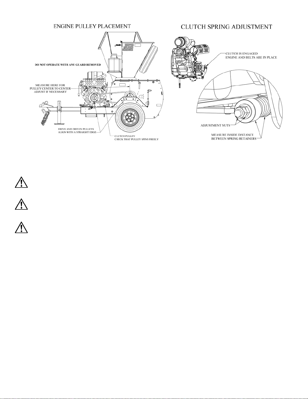
CMS ASSEMBLY INSTRUCTIONS ...................................................................................................4
CMS INTENDED USE..........................................................................................................................4
OPERATOR TRAINING.......................................................................................................................5
ROUTINE MAINTENANCE................................................................................................................5
MAINTENANCE PREPARATION......................................................................................................6
LOCKOUT PROCEDURE....................................................................................................................6
HOUR METER......................................................................................................................................7
ENGINE MAINTENANCE...................................................................................................................8
LUBRICATION REQUIREMENTS.....................................................................................................8
BELT INSTALLATION / REPLACEMENT........................................................................................9
CHIPPER BLADE INSPECTION AND REPLACEMENT...............................................................10
MULCHER HAMMER CHECKING AND REPLACEMENT..........................................................11
ANVIL INSPECTION AND REPLACEMENT .................................................................................13
BATTERY SAFETY INSTRUCTIONS..............................................................................................14
BATTERY MAINTENANCE .............................................................................................................15
CMS TROUBLESHOOTING GUIDE ................................................................................................17
SPECIFICATIONS ..............................................................................................................................18
INDEX..................................................................................................................................................18
WARRANTY OF BARRETO MANUFACTURING EQUIPMENT
Barreto Manufacturing, Inc. warrants all BARRETO equipment to be free of defects in material and
workmanship for a period of one (1) year, dating from the delivery to the original user.
This warranty is in lieu of all other warranties, whether written or implied, and is limited to:
1. Replacement of parts returned to the dealer and/or factory and determined defective upon
inspection. (Replacement for parts to dealers shall be at dealer cost plus shipping charges.)
2. Time for pick-up and/or delivery, transportation of service calls by dealers is excluded.
Manufacturer reserves the right to determine reasonable time required for repair.
Warranty does not apply to damage caused by abuse or neglect. Time and materials required for
normal maintenance and service are also excluded from warranty coverage.
Engines, engine accessories, batteries and tires are warranted by the original manufacturers and
are not covered by the Barreto Equipment Warranty.
Wear parts such as chipper blades, mulching hammers, bearings, belts, pulleys, sheaves, bushings
etc. are also excluded unless it can be determined that a defect has contributed to premature wear.

3104CMS OWNER’S MANUAL 9/5/18 Page 3 of 18
SAFETY MESSAGES
This section covers the method used to announce safety messages. Safety messages appear as appropriate
in this manual and on decals affixed to the machine where a hazard may occur if procedure or instructions
are not followed correctly and completely.
This is the ISO general warning sign it has been adapted for black and white printing.
Standard No.: 7010:2011
It is used in conjunction with the following signal words to communicate a hazard.
From: ISO 3861-2.2004
•DANGER: Indicates an imminently hazardous situation which, if not avoided, will result in
death or serious injury.
•WARNING: Indicates a potentially hazardous situation which, if not avoided, could result in
death or serious injury.
•CAUTION: Indicates a potentially hazardous situation which, if not avoided, could result in
minor or moderate injury.
Study ALL decals on the CMS before operating the CMS.
ALWAYS USE COMMON SENSE AND THINK SAFETY FIRST!
Review the SAFETY INSTRUCTIONS OVERVIEW found in the operator’s manual
Emergency & Medical Contacts:
USA & CANADA: Emergency dial 911
USA & CANADA: American Association of Poison Control Centers: 1-800-222-1222
Outside the USA & Canada (Please fill in the appropriate number)
National Emergency number:_______________
Poison Control Center:____________________
Other:_________________________________

3104CMS OWNER’S MANUAL 9/5/18 Page 4 of 18
CMS ASSEMBLY INSTRUCTIONS
Upon delivery, check for freight damage and missing items. All hardware necessary to fully assemble is
included. There is a pre-shipping inspection sheet and /or a packing slip included, review these to make
sure that all components have arrived.
If there is damage or missing components notify the carrier and Barreto Manufacturing immediately.
AT THE TIME OF WRITING, CRATING / SHIPPING METHODS HAVE NOT BEEN FINALIZED.
ASSEMBLY INSTRUCTIONS MAY VARY.
WARNING: The CMS and components are heavy. Lift the CMS by mechanical means: while lifted
support the CMS with jack stands. Always team lift heavy components: “Lifting loads heavier than about
50 pounds will increase the risk of injury.” (OSHA)
•Install the tongue. Refer to drawing 001CMS
oUsing a wire puller, pull the provided electrical wire through the top hole in the front of
tongue. Depending on crating method, you will either need to attach the vehicle adapter to
the wire or connect the light plugs to the lights, follow the zip tie points (two small holes)
back to each light and zip tie the wire at each point. Run the wire behind the axle.
oThe tongue installs with 3 bolts and 3 lock nuts. Fit up all 3 bolts and lock nuts before
tightening. The lock nuts must go on the battery side.
oAttach the safety chain with the quick link: the threaded side of the quick link pushes
through the slot on the tongue flips around and hooks through the lower hole.
•Install the Chipper hopper: See drawing E3104CMS & 009CMS.
oThe chipper hopper installs with two bolts, one on each side.
oMake sure the hopper lock pin lines up with the latch, adjust if necessary.
•Install the tires: See drawing 0013CMS.
oTighten bolts in a star pattern, final torque 100 lb-ft.
•Check engine oil level, the engine may be drained of gas and oil prior to shipping.
oSee engine operator’s manual for checking / filling instructions.
Refer to your assembly (exploded views) manual for drawings.
CMS INTENDED USE
This machine is designed to chip, shred, and mulch wood, leaves, grass and other such plant materials.
The chipper can handle tree limbs up to 4 inches in diameter while the mulcher hopper can handle leafy
branches up to 1 inch in diameter and other such soft but bulky plant material.

3104CMS OWNER’S MANUAL 9/5/18 Page 5 of 18
OPERATOR TRAINING
Everyone who operates a CMS or assists the CMS operator needs to know the following aspects of
machine operation before operating the CMS. They are important and must be a part of operator training.
Rental companies need to understand and be able to explain and demonstrate all of the machine
operations to each rental customer including:
•KNOW AND UNDERSTAND ALL SAFETY POINTS AND CONSIDERATIONS
•Check that all guards/covers and safety decals are in place
oIf an engine driven component is exposed or accessible, a guard is missing.
•Know how to properly connect the CMS to a towing vehicle
•Know the towing position of the: swivel jack or stand; chipper hopper and rear flap
•Know the operating position of the: swivel jack or stand, chipper hopper and rear flap
•Understand the CMS capabilities and intended use
•Know how to start and stop the engine
•Know how to engage and disengage the clutch
•Understand how to prevent clogs
•Know how to lock the chipper disk / mulcher rotor
•Know how to safely clear clogs from the chipper and mulcher hoppers
For detailed instructions on CMS operation see the operator’s manual in the canister attached to
the chipper hopper.
ROUTINE MAINTENANCE
Routinely check the condition, clean, tighten, repair, or replace as necessary the following:
•Safety decals
•Muffler guard
•Fuel lines
•Fasteners
•Mulching Hammers
•Anvil
•Belts
•Chipper Blades
•Engine Oil
•Grease Points
Clean safety decals often using soap and water. DO NOT use abrasive cleaners or solvents such as
mineral spirits that will damage the decals. Replace any damaged (unreadable) or missing decals. If you
replace a machine part that has one or more decals affixed to it, replace the decals also. Replacement
parts and decals can be purchased from Barreto Manufacturing, Inc. When attaching decals, the
temperature of the mounting surface must be at least 40°F (5°C) and must be clean and dry.
DO NOT pressure wash or hose down any bearing, water can enter the bearing and dramatically reduce
bearing life. Wipe away excess grease, dirt and grime that accumulate on or near a bearing.
Service the engine according to the engine owner’s manual. Follow the directions for all aspects of
service including air filter change, oil level checking, filling, draining, disposal of engine oil, disposal of
petrol/gasoline, and off-season long-term storage.
Off-season long-term storage of the CMS can be at any ambient temperature.

3104CMS OWNER’S MANUAL 9/5/18 Page 6 of 18
MAINTENANCE PREPARATION
WARNING: The engine, exhaust pipe and engine oil get hot during operation. Allow adequate time for
the engine and engine components to cool before beginning maintenance.
DANGER: BEFORE beginning any maintenance on the CMS that requires a guard be removed or
exposes someone to a part that moves during operation, the CMS lockout procedure must be followed.
Only trained and qualified personnel should perform maintenance or repairs of the CMS or the battery.
LOCKOUT PROCEDURE
Manufacturers recommended lockout procedure: To render the CMS inoperable.
1. DISCONNECT THE BATTERY.
2. REMOVE THE KEY.
3. LOCK THE CHIPPER DISK.
1. Disconnect the battery: See: BATTERY SAFETY INSTRUCTIONS first,
Disconnect the negative battery cable where the cable connects to the CMS chassis prevent the cable from
touching any part of the engine or chassis. Then disconnect the negative cable from the battery. Store the
cable where only the person performing the maintenance has access to the cable. (When reconnecting,
connect the battery first, chassis second)
WARNING: The battery contains sulfuric acid that can cause blindness and severe burns. Avoid contact
with eyes, skin and clothing. Read the section: BATTERY SAFETY INSTRUCTIONS, in this manual.
2. Remove the key:
Attempt to start the engine with the key. This should ensure that any residual power in the system is
drained. Turn the key to off and remove the key. Store the key where only the person performing the
maintenance has access to the key.
3. Lock the chipper disk:
Loosen the bolt holding the chipper disk lock cover, swing the cover up and snug the bolt down. The
chipper disk lock pin is stored behind and to the right of the chipper hopper. Insert the chipper disk lock
pin into the lock hole and through the hole in the chipper disk. If needed, use the disk lock pin to turn the
chipper disk until it can be inserted into the chipper disk. The disk can be turned in either direction.
WARNING: DO NOT use your fingers, hands or any other body part to turn the chipper disk. The
chipper is heavy and has sharp blades.
See figure: TO RENDER THE CMS INOPERABLE on the next page:
This is a recommended lockout procedure in accordance with OSHA 1910.147(a)(3)(i) it is your
responsibility to establish and utilize procedures for affixing appropriate lockout/tagout devices.
For more information on developing vehicle maintenance lockout/tagout procedures refer to OSHA,
DIRECTIVE NUMBER: CPL 02-00-147.

3104CMS OWNER’S MANUAL 9/5/18 Page 7 of 18
HOUR METER
The DGI®TACH/HOUR hour meter tracks the hours of machine operation in order for routine
maintenance to be performed on a timely basis.
Your DGI® hour meter is pre-set at the DGI® factory to go into Flash Alert mode at 25-hour
intervals. Although the engine manufacturer does not require changing engine oil this often, due to
heavy-duty use and extreme conditions inherent to CMS use, Barreto Manufacturing strongly
recommends frequent oil changes.
Refer to this manual for equipment service requirements and to the Engine Manual for other engine
service requirements.
While Flash Alert is active, hold the tip of the RESET TOOL (Key Kancel Wand) against the meter
as shown. Within several seconds the display will stop flashing indicating the Service Interval has
been reset. If the wand gets lost, a small mechanic’s pick-up magnet will reset the meter.
RESET TOOL

3104CMS OWNER’S MANUAL 9/5/18 Page 8 of 18
ENGINE MAINTENANCE
Follow the instructions provided in your engine operator’s manual for all engine maintenance and
procedures.
Barreto Manufacturing has added an engine oil drain hose to your engine to facilitate easier oil changes.
Due to heavy duty use inherent to CMS operation Barreto Manufacturing recommends that you change
your engine oil every 25 hours.
LUBRICATION REQUIREMENTS
Grease at the intervals indicated in the following illustration of grease points. Wipe away excess grease,
KEEP GREASE OFF OF BELTS.

3104CMS OWNER’S MANUAL 9/5/18 Page 9 of 18
BELT INSTALLATION / REPLACEMENT
The belts on the CMS have been designed for heavy duty use, high shock loads and smooth clutching. It
is recommended that you replace your belts with belts from Barreto Manufacturing.
WARNING: The CMS must be rendered inoperable before removing the belt cover or beginning any
work on the belts. See the MAINTENANCE PREPARATION section.
To replace your belts:
1. Remove the belt cover.
2. Disengage the clutch. (If not already disengaged).
3. Check that the clutch pulley spins freely. Replace pulley or bearings as necessary.
4. Remove the clutch pins, refer to drawing 004CMS
5. The belts should remove from the pulleys without adjusting the engine position. Adjust engine
position if necessary. Remove the belt furthest from the engine first.
6. Install new belts, DO NOT PRY OR FORCE THE BELTS ON, if they are too tight to install adjust
the engine position so that the belts can install easily.
7. Install the clutch pins, refer to drawing 004CMS.
7.1. With the clutch disengaged, the clutch pins cause the belt to bunch around the pulley (sheave).
The clutch pin positions are adjustable. Adjust as needed and tighten bolts.
8. Engage the clutch. Check that there is clearance between the belt and the clutch pins. The belt must
not touch the clutch pin while the clutch is engaged. Loosen and re-adjust if necessary.
9. Disengage the clutch and check that the belt bunches around the pulley. Re-adjust if necessary.
10. Reinstall the belt cover before running your engine
Check engine / pulley placement:
Alignment between the drive pulley and the driven pulley is critical for proper clutch function and belt
life. Use a straight edge to make sure that the drive and driven pulleys are aligned. We have found that the
clutch works well with the center of the drive pulley 25-15/16” away from the center of the driven pulley,
adjust if necessary. (See image: ENGINE PULLEY PLACEMENT)
Check belt tension:
The belts must be properly tensioned. Belt tension is controlled by the springs on the clutch assembly.
With the belts, clutch pins and engine in place engage the clutch and measure the distance between the
spring retainers. The distance between the spring retainers should be 1.400”: to adjust this turn the nuts in
or out as necessary, using the combination of two nuts to position and secure them in place. If the belt
slips while the clutch is engaged, it is too loose and the distance between the spring retainers must be
reduced. Small adjustment of the spring retainers will result in large tension adjustments; adjust in
increments of 0.005” to 0.010”. (See image: CLUTCH SPRING ADJUSTMENT)
NOTICE: Spring loaded belt tension checkers should not be used with aramid or glass cord belts such as
the belts supplied for the CMS.
See figures: ENGINE PULLEY PLACEMENT & CLUTCH SPRING ADJUSTMENT on the next page.

3104CMS OWNER’S MANUAL 9/5/18 Page 10 of 18
CHIPPER BLADE INSPECTION AND REPLACEMENT
WARNING: The CMS must be rendered inoperable before removing the chipper blade access cover. See
the MAINTENANCE PREPARATION section.
WARNING: Never turn the chipper disk with your hand or any other body part as serious injury may
occur. The chipper disk lock pin may be used to turn the chipper disk.
CAUTION: Avoid touching the chipper blades. The chipper blades are extremely sharp and may cut any
body part that comes in contact.
To inspect chipper blades:
Remove the chipper blade access cover, see image: CHIPPER BLADE ACCESS and drawing 002CMS.
Stay clear of the blades, unlock and turn the chipper disk as necessary to position the chipper blade in the
blade access area. Lock the disk when the blade is within the blade access area.
To replace chipper blades:
The chipper blades have two cutting edges, when the first edge has dulled the blades can be reversed and
the new cutting edge used. When both edges have dulled the blades may be sharpened or replaced.
The bolts holding the chipper blade were installed with high strength (red) threadlocker. If you cannot get
a bolt to loosen apply heat, such as from a heat gun, while applying torque to remove the bolt.
When reinstalling the chipper blade use high strength red threadlocker and torque bolts to 102 lb-ft.
NOTICE: DO NOT drop bolts or tools into the chipper disk area; it will be difficult to remove.

3104CMS OWNER’S MANUAL 9/5/18 Page 11 of 18
Blade sharpening information:
The blades should only be sharpened by a professional with a professional precision knife grinder. Both
sides of both blades must be sharpened at the same time. To keep the blades at the same weight there
must be less than 0.010” difference in the blade profile.
MULCHER HAMMER CHECKING AND REPLACEMENT
WARNING: The CMS must be rendered inoperable before removing the chipper blade access cover. See
the MAINTENANCE PREPARATION section.
To inspect the mulching hammers:
•Use the rear flap adjustment pin to hold the rear flap up
•Remove the top pin from the mulcher screen
•Pull the mulcher screen down
See the OPERATOR’S MANUAL: Figure CLEARING MULCHER CLOGS
CAUTION:The surfaces and edges on or around the mulching rotor including the mulching hammers
can be sharp. Be careful while handling. Wear gloves and all appropriate personal protective equipment.
To remove & replace the mulching hammers: See drawing 003CMS in your Assembly Manual and
figure CLEARING MULCHER CLOGS in your operator’s manual.
1. Remove the belt guard; this will expose a rotor pin access slot in the side plate.
2. Set the chipper disk lock. The chipper disk lock has a locking position for each of the rotor pins.
3. Make a note of the order in which the spacer / hammers were put on the rotor pin.
4. Remove the bolt and the outer retaining washer from the rotor pin. The retaining bolts were installed
with threadlocker. If the bolt will not loosen apply heat and torque simultaneously. DO NOT apply
excessive heat to the bolt or other components. Clean old threadlocker from the bolt and rotor pin.
5. Push the rotor pin in (towards the chipper disk) and remove the shaft locking flange.
6. Slowly pull the rotor pin out (away from the chipper disk)
7. Carefully remove the hammers and spacers. The hammers and spacers nearest the chipper disk will
come out first.

3104CMS OWNER’S MANUAL 9/5/18 Page 12 of 18
8. Flip, rotate or replace the hammers such that a fresh hammering surface is being used and all worn
surfaces are in the same position for each hammer.
9. Re-install the hammers and spacers in the same pattern noted in step 3. The hammers and spacers
furthest from the chipper disk must be installed first.
10. With all hammers and spacers in place push the rotor pin back toward the chipper disk and insert the
shaft locking flange.
11. Pull the rotor pin out, (away from the chipper disk). Install the bolt and the outer retaining washer.
Apply high strength (red) threadlocker to the bolt and tighten to 30 lb-ft.
12. Using a permanent marker make a mark on the rotor to indicate that the rotor pin is done.
13. Repeat from step 2 for all rotor pins.
Always replace any damaged or worn out components.
Assembly is reverse of removal.
The mulcher hammers have four hammering surfaces, as the hammers dull they can be flipped, rotated
and flipped again. The mulching hammers cannot be sharpened. After all four corners of the hammers
have dulled they must be replaced.
Clearances in the mulching hammer are tight, disassembly and assembly can be difficult. BE PATIENT.

3104CMS OWNER’S MANUAL 9/5/18 Page 13 of 18
ANVIL INSPECTION AND REPLACEMENT
WARNING: The CMS must be rendered inoperable before removing the chipper hopper. See the
MAINTENANCE PREPARATION section.
Refer to drawing 002CMS in your Assembly Manual and figure ANVIL ALIGNMENT / PLACEMENT
on the next page of this manual.
Quick anvil inspection:
With the engine off and the chipper disk at rest, a quick visual inspection of the anvil may be made. Point
a flash light and look down the chipper hopper. The anvil is inside the fixed portion of the chipper hopper
and sits next to the chipper blades. Look for any obvious signs of damage.
WARNING: Only perform the Quick anvil inspection with the engine off and the chipper disk
stationary. The blades are sharp, death or serious injury may occur.
Detailed anvil inspection:
Remove the chipper hopper. This will allow access to the anvil.
If the edge of the anvil is excessively worn it may be flipped to the fresh side. Do not use the edge on the
same side as a worn edge.
If the anvil has two worn edges, is damaged, has chunks missing or cracks, it must be replaced.
As the anvil edge wears, as long as the anvil is not damaged, the anvil may be moved to correctly re-align
the anvil. See instructions below.
Anvil alignment / placement:
The anvil must be correctly aligned with the chipper blade for the chipper to work correctly.
Rotate the chipper disk so that a blade is next to the anvil. The anvil should be 0.030” (0.76mm) to 0.060”
(1.52mm) max away from the blade. Adjust within this range as necessary.
WARNING: Exercise extreme caution while measuring the gap between the chipper blade and the anvil.
The chipper disk does not lock in a position to easily allow the measurement of the gap between the blade
and the anvil. Wear gloves and all appropriate personal protective equipment.

3104CMS OWNER’S MANUAL 9/5/18 Page 14 of 18
BATTERY SAFETY INSTRUCTIONS
Only trained and qualified personnel should perform maintenance or repairs of the CMS or the battery.
WARNING: The battery contains sulfuric acid that can cause blindness and severe burns. Avoid
contact with eyes, skin and clothing.
WARNING: Battery fumes are flammable and explosive. Avoid exposing the battery to sparks and
flames. Sparks can be created near the battery when handling battery cables or jumper cables.
WARNING: The battery, posts, terminals, and related accessories contain lead and lead
compounds, chemicals known to the State of California to cause cancer and reproductive harm.
WARNING: Wear appropriate personal protective equipment when handling the battery. Shield entire
face, especially your eyes, wear rubber gloves and a rubber apron to reduce the risk of acid burns.
Battery caps must be tightly in place if the battery has removable caps.
First Aid Measures from Material Safety Data Sheet, for sulfuric acid: ScienceLab.com
•Eye Contact: Check for and remove contact lenses. Immediately flush eyes with plenty of water for
at least 15 minutes. Cold water may be used. Get medical attention immediately.
•Skin Contact: Immediately flush skin with plenty of water for 15 minutes while removing
contaminated clothing and shoes. Cover irritated skin with an emollient. Cold water may be used.
Wash clothing before reuse. Thoroughly clean shoes before reuse. Get medical attention
immediately.
•Serious Skin Contact: Wash with a disinfectant soap and cover the contaminated skin with an anti-
bacterial cream. Seek immediate medical attention.
•Inhalation: If inhaled, remove to fresh air. If not breathing give artificial respiration. If breathing is
difficult, give oxygen. Get medical attention immediately.
•Serious Inhalation: Evacuate the victim to a safe area as soon as possible. Loosen tight clothing
such as a collar, tie, belt, or waistband. If breathing is difficult, administer oxygen. If the victim is
not breathing, perform mouth-to-mouth resuscitation. Seek immediate medical attention
WARNING: It may be hazardous to the person providing aid to give mouth-to-mouth resuscitation when
the inhaled material is toxic, infectious or corrosive.
•Ingestion: DO NOT induce vomiting unless directed to do so by medical personnel. Never give
anything by mouth to an unconscious person. Loosen tight clothing such as a collar, tie, belt or
waistband. Get medical attention if symptoms appear
•Serious ingestion: Not available
Emergency & Medical Contacts:
USA & CANADA: Emergency dial 911
USA & CANADA: American Association of Poison Control Centers: 1-800-222-1222
Outside the USA & Canada (Please fill in the appropriate number)
National Emergency number:_______________
Poison Control Center:____________________
Other:_________________________________

3104CMS OWNER’S MANUAL 9/5/18 Page 15 of 18
BATTERY MAINTENANCE
WARNING: Read the section: BATTERY SAFETY INSTRUCTIONS, before handling the
battery.
The original Interstate Batteries equipped on the CMS are considered to be maintenance free. However
some maintenance will help your battery last longer. Temperatures below freezing or over 90°F (32°C)
will reduce the life of your battery. If the CMS is not going to be used for a season, store it fully charged
in an area where the temperature will stay between freezing and 90°F (32°C). This will help prolong your
battery life.
NOTICE: The battery acid is corrosive and can damage your machine. Keep the battery clean and avoid
getting battery acid on your machine.
Always recycle / dispose of your old batteries properly. Most places that sell automotive batteries will take
your old battery and pay you for it. DO NOT dump your battery. DO NOT put your battery in a dumpster.
Always replace any damaged battery or battery components, such as wires, clamps, lugs, fasteners, isolators,
covers, etc.
To remove your battery: Engine must be off. All engine switches must be in the OFF position.
•Disconnect the ground cable at the CMS chassis and position it to not touch any CMS component.
•Disconnect the ground cable at the battery and set it aside.
•Disconnect the positive cable from the battery; the cable may remain connected to starter motor.
•Remove the battery from the CMS. Place on a clean, dry, level, non-conductive surface. Keep
away from flames, sparks and heat sources.
•DO NOT store where the ambient temperature is less than freezing or hotter than 90°F (32° C).
To install your battery: Engine must be off. All engine switches must be in the OFF position.
•Place battery in battery compartment.
•Connect the positive cable to the battery and the starter motor.
•Make sure that the ground cable is not touching any CMS component.
•Connect the ground cable to the battery.
•Install the battery isolator and cover.
•Connect the ground cable to the CMS chassis.
To clean your battery: information from www.interstatebatteries.com
•Disconnect your battery. See: To remove your battery: the battery may remain in the CMS.
•Make sure vents caps are pressed securely into battery.
•Clean terminals and lugs with a mixture of baking soda and water. A wire brush may be used.
•Clean CMS components near the battery with baking soda and water. DO NOT use a wire brush.
•Rinse with clean water and allow enough time for water to dry.
•Coat terminals and wire lugs with dielectric grease.
•Connect your battery. See: To install your battery:

3104CMS OWNER’S MANUAL 9/5/18 Page 16 of 18
To check the electrolyte level and add water: Information from www.interstatebatteries.com
It is particularly important to check electrolyte levels during hot weather.
•Pry removable vent caps off with a flat head screw driver. You will see individual vent wells.
•Carefully look into each individual cell to make sure that the water is covering the lead plates.
•Add distilled water to any cells that are low on water. DO NOT OVER FILL, add water slowly,
add just enough water to cover the lead plates or to a fill line indicator if equipped.
•Re-install removable vent caps; make sure that they are fitted all the way in place.
DANGER: Keep your eye away from the battery while looking into a battery cell. Stay a safe distance
back and use a flash light. Serious injury including blindness will occur.
WARNING: Wear appropriate personal protective equipment when handling the battery. Shield entire
face, especially your eyes, wear rubber gloves and a rubber apron to reduce the risk of acid burns. Battery
caps must be tightly in place if the battery has removable caps.
NOTICE:Only use distilled water, available at most grocery stores. Tap water and other drinking water
have impurities that will damage your battery.
To recharge the battery:
Read, understand and follow all safety and operating instructions from your battery charger. Make sure
that your battery charger is rated appropriately to charge the battery. If voltage and amperage can be
adjusted on your charger, make sure they are adjusted correctly to your battery. DO NOT over charge
your battery. Interstate Batteries recommend using a 3-stage automatic 12 volt/10 amp charger for
automotive batteries such as the MT-34 battery, no Interstate Batteries charger type recommendation has
been found for lawn and garden batteries such as the SP-35 battery.

3104CMS OWNER’S MANUAL 9/5/18 Page 17 of 18
CMS TROUBLESHOOTING GUIDE
At Barreto Manufacturing we take pride in our machines and our customer service. If you are having
difficulty with your machine please call us at the number listed on the front page of this manual.
WARNING: Always use extreme care when troubleshooting or making adjustments. Stay clear of all
moving parts or parts capable of moving while the engine is running or capable of running. The CMS
must be rendered inoperable before removing any cover. See the MAINTENANCE PREPARATION
section.
Also review: CMS OPERATORS TROUBLESHOOTING GUIDE, in the Operator’s Manual.
The CMS stalls as soon as anything is fed into either hopper.
Rotor stops, engine remains running:
The belts are too loose or worn out, replace worn out belts.
Check engine / pulley placement and belt tension.
See: section BELT INSTALLATION /REPLACEMENT
Rotor and engine stop / stall:
Make sure the engine is running at full throttle before feeding material.
Check your engine Operator’s manual and make sure the engine is up to date on all maintenance.
Old oil, dirty filters and obstructed air intakes will reduce engine performance.
Make sure that you are using fresh gasoline. Gasoline has a shelf life of about 90 days.
Check that all grease points have been greased and that bearings are in good condition.
Check that there is nothing impeding the rotors movement.
The CMS vibrates excessively:
If the vibration is coming out of the engine: See engine Operator’s manual, contact engine dealer.
Make sure that the engine is up to date on all maintenance.
If the vibration is coming from other CMS components:
Check the mulcher rotor, check for missing hammers, make sure that every hammer can swing on
the rotor pin and that nothing is stuck to the rotor.
Check the chipper disk, make sure that all looks to be in good repair and that nothing is stuck to it.
The chipping blades dulled really fast:
It is more likely that the Anvil has moved and is not in the correct position.
See section: ANVIL INSPECTION AND REPLACEMENT
If non-plant material has been fed into the chipper the blades will dull fast and may be damaged.

3104CMS OWNER’S MANUAL 9/5/18 Page 18 of 18
SPECIFICATIONS
MODEL NUMBERS 3104CMS
DIMENSIONS (APPROXIMATE, STORAGE POSITION)
GVWR: 1400 lbs. (635 kg)
Height: 73” (1.85m)
Length: 89” (2.26m
Width: 56” (1.42m)
Axle Track: 48” (1.22m)
ENGINE
Engine: Vanguard™ 31.0 Gross Hp
Fuel: Gasoline
Power: 31hp (22.8 kW) at 3600 RPM
Fuel Capacity: 5 U.S. Gallons (18.9 liters) External tank
Engine Oil Capacity: 2.43 U.S. Quarts (2.3 liters)
Electric Start: Standard
Hour Meter: Standard
INDEX
ASSEMBLY INSTRUCTIONS, 4
BATTERY MAINTENANCE, 15, 16
CHIPPER ANVIL, 2, 13, 14, 18
CHIPPER BLADES, 5, 10, 11, 14
DECALS, 3, 5
HOUR METER, 7
INTENDED USE, 4
LUBRICATION, GREASE, 5, 8, 16, 18
LUBRICATION, OIL, 4, 6, 7, 8, 18
MAINTENANCE, 2, 5, 6, 7, 8, 14, 15, 18
MULCHER HAMMER, 11
OPERATOR TRAINING, 5
SPECIFICATIONS, 18
TROUBLE SHOOTING, 17
WARRANTY, 2
Table of contents