Barrett 401 User manual

#0-313A-SBA (6/01)
Page 1 of 14 pages
BARRETT CENTRIFUGALS INC.
1-800-228-6442
Manufacturers of Reliable Centrifuges for the Metalworking Industry
INSTALLATION AND OPERATING INSTRUCTIONS FOR STANDARD BARRETT MODEL
401 & 1101 COMBINATION EXTRACTORS
Includes instructions for optional heaters and 45-gallon capture tank
Serial No. 4010263-E Motor No. 6R3467
This machine is designed to spin machining fluids (cutting oils, coolants, etc.) from industrial
sludge. Prior to using it on any other application you should contact Barrett Centrifugals Inc.
to determine if the machine can be used successfully and safely.
THIS EQUIPMENT MUST BE INSTALLED, WIRED, OPERATED AND SERVICED BY
QUALIFIED PERSONS ONLY. READ, UNDERSTAND AND COMPLY WITH THESE
INSTALLATION, OPERATING AND SAFETY INSTRUCTIONS BEFORE INSTALLING,
OPERATING OR SERVICING THIS EQUIPMENT.
SAFETY IS ESSENTIAL
To insure safe machine operation proper installation and thorough operator training are
required. Read and observe all instructions and specific precautions included in this manual
and most importantly, think before you act and be careful.
#0-313A-SBA (6/01)
Page 2 of 14 pages
BARRETT CENTRIFUGALS INC.
1-800-228-6442
This machine is not suitable for use with volatile or
flammable liquids!
This Barrett machine is not equipped for use in hazardous locations as defined by the National
Fire Protection Association (NFPA). NFPA guidelines designate locations that may be
hazardous due to ignitable atmospheres caused by generation of vapors from flammable or
combustible liquids. During operation, friction within the centrifuge may bring some surface
temperatures above the flash point of Class I and Class II Liquids (over 140 degrees F) thereby
creating an ignitable atmosphere within and around the machine. For this reason no fluid
classified by NFPA as Flammable (Class I) or Combustible (Class II) should be used in
this machine. Such use may cause a flash fire or explosion resulting in serious
personal injury and/or property damage. For more information see NFPA 70 (the National
Electrical Code) and NFPA 30.
Modifications to programmable equipment should be
made by authorized and qualified personnel only!
This machine is equipped with a programmed logic controller (PLC) and, possibly, a variable-
speed drive (VFD). Altering or tampering with the settings that are programmed into these
devices could cause the machine to malfunction. It could also lead to failure of the safety
controls and devices meant to protect personnel and change the motor speed that could
severely damage the machine.
Only qualified personnel should attempt to change the settings. Before attempting any
alterations we strongly urge that you contact Barrett Centrifugals Inc. to discuss any
changes that you are considering or desire.
GENERAL SAFETY PRECAUTIONS
SAFETY IS EVERYONE'S RESPONSIBILITY
Barrett machines are designed and built with safety in mind. However, high voltage and
rotating parts associated with an electrically driven centrifugal machine can cause serious
injury if operated improperly. All operators must be instructed in the safe operation of this
machine. Personnel should be instructed to:
1. Have all installation, maintenance and repair work performed by qualified people.
2. Disconnect and lock out all power sources before doing any work on the equipment.
3. Make the electrical connections and properly ground the equipment in accordance with
OSHA Electrical Standards, the National Electrical Code and local codes.
4. Never open the lid when the internal components are rotating or serious injury may
result!

#0-313A-SBA (6/01)
Page 3 of 14 pages
BARRETT CENTRIFUGALS INC.
1-800-228-6442
5. Keep hands, hair, clothing and tools away from all moving parts when operating or
repairing the equipment.
6. Never operate the equipment unless all guards and protective covers are in place. Do
not attempt to bypass safety devices to operate the equipment.
7. Never use this machine with flammable liquids or a fire or explosion may result
causing serious injury.
If you encounter operating difficulties please contact the Barrett Customer Service
Department at 1-800-228-6442.
MACHINE SET-UP
WARNING! Do not attempt to lift the machine by the rotating assembly! Doing
so will damage the motor and/or pan. Lift the machine using all four drum access
holes (9" x 7" opening on the lower part of the drum) or the inside lip of the drum head
(with lid open) using a multi-hook chain or sling.
Locate the machine in the desired position. Transfer the bolt hole locations from the base to
the floor. Level the machine by shimming under the base at the anchor bolt holes to insure
full, solid support. On wooden floors, straddle the beams and use through bolts. On concrete
floors, Barrett recommends the use of epoxy-set type anchors to secure the machine to the
floor. The machine must be absolutely solid with the floor. Do not set in wet cement!
Do not run machine without anchoring or vibration may allow it to move about and
damage the electrical connections.!
WIRING
The wiring of this equipment should be performed by a qualified electrician, and be in
accordance with OSHA Electrical Standards, the National Electrical Code and local codes,
and also, be in accordance with the wiring diagram provided with these instructions. A
control panel, with a disconnect switch, motor starters, transformers, fuses, cycle timer, PLC
and D.C. brake circuit is provided for wall mounting.
The customer must provide service to the panel. Feed lines should be connected to the
panel's disconnect switch. The full load current is approximately 32 amps. Feed lines
should be number 8 wire or larger. Fusing in the panel is per equipment requirements and
should not be altered without first consulting the factory.
The main machine motor, motor cooling blower, if provided, and auxiliary devices are pre-
wired, at the factory, to the machine junction box. Matching numbered terminal strips in the
junction box and control panel must be wired together, via conduit, at installation. High

#0-313A-SBA (6/01)
Page 4 of 14 pages
BARRETT CENTRIFUGALS INC.
1-800-228-6442
voltage wiring and control wiring should be fed through separate conduit lines to avoid faulty
signals generated by electrical noise.
Fig. 1. Motor cooling blower
Machines supplied with a motor driven cooling
blower are factory wired so that the blower must
be on for the machine to operate. The motor
cooling blower is set at the Barrett factory to
remain on for 10 minutes after a cycle ends.
Rotation of the blower (if provided) and main drive
motor will have to be checked after power to the
control panel has been obtained. To check the
rotation, push the START push button and
immediately cut power to the machine by turning the main disconnect on the control panel to
Off. Observe the direction of the blower motor as the blower fan coasts to a stop. It should be
rotating counterclockwise when viewing from the front of the machine (blowing cool air into
the machine). To change blower rotation, disconnect the power supply and switch two of the
power leads supplying the main disconnect. This insures that when the blower is rotating
properly all other components are rotating properly as wired at the factory.
Ground all equipment according to OSHA Electrical Standards, the National Electrical Code
and local codes.
NOTE: For all machines with a motor cooling blower, and trunnion dump arms
mounted on the right-hand side of the machine the customer must provide a source of
clean, dry, ambient air piped to enter the blower. Failure to comply may allow dry
chips being dumped to be sucked into the blower and result in an accumulation of
foreign material within the motor, ultimately causing premature motor burnout.
THE ROTATION DETECTOR / DC BRAKE
The Rotation Detector and DC Brake circuit designed for this machine are intended for the
operator's safety. The machine cannot be started unless the lid is closed and the lid latch is
locked. Once the machine has been started the lid cannot be opened until the rotating
assembly has come to a complete stop. A green signal light located on the push button
station will light up, indicating that the machine has stopped spinning. When the green light is
illuminated the lid latch can be disengaged and the lid opened. The rotating assembly is
brought to a stop with a D.C. braking circuit that works in conjunction with a photoelectric
sensor and the PLC (Programmable Logic Controller) located within the control panel.
In the event of a power failure the lid latch will stay locked to prevent premature opening of
the lid. There is no manual bypass.
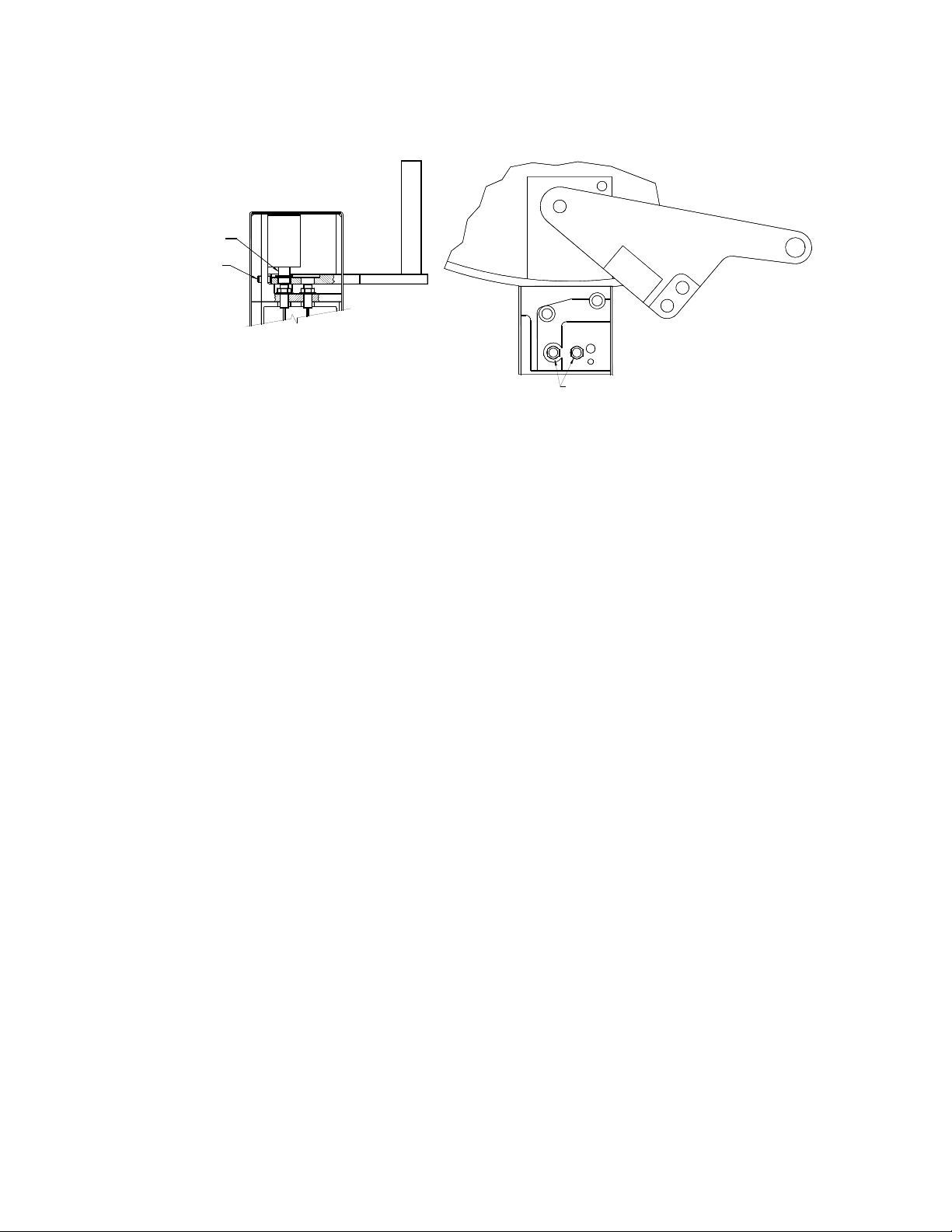
SAFETY LID LATCH (Refer to Fig. 2)
This machine is equipped with a safety lid interlock that works in conjunction with the DC
brake circuit, rotation sensor and PLC to prevent opening of the lid while the machine is
rotating. The solenoid pin in the latch housing provides the necessary mechanical lockout.
The machine cannot be started with the lid open or the latch unlocked. If in the locked
#0-313A-SBA (6/01)
Page 5 of 14 pages
BARRETT CENTRIFUGALS INC.
1-800-228-6442
LATCH OPEN
INDUCTIVE SENSORS
(TOP VIEW)(FRONT VIEW)
LATCH CLOSED
LATCH STOP
SET SCREW
ADJUSTMENT
SOLENOID PIN
position, the latch cannot be opened with the power off.
Fig. 2. Lid latch detail.
In the operation of your machine it is important to operate the lid latch handle properly
to prevent an inconvenient lockout by the safety lid latch.
1. The machine is shipped in an unlocked but secured condition. Cut away the wire tie that
holds the locking lever. The lever can then be retracted and the lid raised.
2. Once all wiring to the machine is complete (refer to the "Wiring" section of these
instructions), turn the electrical power to the machine on.
3. Close the lid and slide the locking lever into the slot in the latch housing. This action
triggers a latch-close sequence. As the latch passes over the inductive sensors a
sequence of signals is sent to the PLC. If the sequence is verified and completed in the
given amount of time a flashing green light indicates that the machine is properly latched
and ready to start. (If the green light does not flash, simply retract the lever all the way to
the right and start the process over.)
4. When the START push button is pressed the solenoid pin drops and the green light goes
out. The pin prevents the latch from being opened. The machine will spin for the time set
on the manual timer within the control panel. Normal spin time is 30 - 45 minutes.
5. When the time has elapsed, the DC brake will activate. After the machine brakes to a stop
the solenoid is energized, lifting the pin, and the green indicator light will illuminate.
6. The lid may now be opened. To open the lid, slide the lever out of the latch housing. The
machine can only be unlatched with the power on and the green OPEN light illuminated.
In the event of a power failure the solenoid is disabled. The lid may not be opened until
power is supplied. If a momentary power loss occurs during a ‘run’ condition the latch will
not unlock until the spindle coasts to a stop.

#0-313A-SBA (6/01)
Page 6 of 14 pages
BARRETT CENTRIFUGALS INC.
1-800-228-6442
The safety lid latch circuit is designed to prolong the life of the solenoid and improve initial
pick-up force. This is accomplished by providing a ½ second burst of 24-volt DC power to
the coil, then cutting back to approximately 12 volts DC. The voltage reduction circuit can
be by-passed at any time by pushing the STOP push button.
Should the solenoid pin become stuck ‘down’ due to locking lever interference, move the
lever slightly to free the pin and press the STOP push button momentarily. To prevent this
problem, do not jam the locking lever against the solenoid pin at any time! It is not
necessary to force the handle against the pin to verify latching! Smooth and gentle
works fine.
DUTY CYCLES
Barrett standard machine maximum duty cycles are as follows:
Model Max. Load Max. No. Start-Stop Cycles/Hr
401 225 lbs. 20
1101 425 lbs. 15
A note about load size. Some sludges (for instance, cast iron) are denser than others. Metal
type and fine size can affect the weight of a load. Do not be tempted to exceed the load sizes
noted above. They will accommodate most sludge types. Remember: a pound of sludge will
effectively weigh hundreds of pounds under centrifugal force. Overloading may cause
machine failure and damage to the machine or injury to personnel. Do not overload!
THE 1101-E AND 1101-SES PANS AND COVERS ARE MATCHED SETS AND
ARE NOT INTERCHANGEABLE! DO NOT ATTEMPT TO RUN THE INCORRECT
COVER WITH THE CHOSEN PAN OR MACHINE DAMAGE MAY RESULT!
1101E EXTRACTOR PAN & COVER
When operating this machine use care to load the pan evenly to insure a good running
balance. Make sure all guards and covers are in place.
l.Before operating the machine be sure that provisions have been made to capture extracted liquid
from the outlet at the rear of the machine.
2.Adjust the cycle timer 1TRE. Barrett recommends an initial setting of three minutes for the 1101E
(the SES will require a longer cycle time. Close and latch the control panel door. (Note: The
required cycle time will vary with the application and must be determined through
experimentation.)
3.Turn power on at main disconnect; push the "Blower Start" button located on control panel door.
The green "OPEN" light will light within 2-4 seconds.

#0-313A-SBA (6/01)
Page 7 of 14 pages
BARRETT CENTRIFUGALS INC.
1-800-228-6442
NOTE: Machine is wired so that cooling blower must be on for machine to operate (if
so equipped).
4.Open the lid and remove the pan cover and pan from the machine using an overhead hoist.
5.Fill the pan (always outside of the machine) with the product. Make sure the work is evenly
distributed to avoid an out of balance condition.
6.The machine has been furnished with a pan guide tool to assist the operator in positioning the pan
onto the spindle. The pan guide tool should be placed onto the spindle over the top threads.
Lower the loaded pan onto the pan guide tool and spindle of the machine until it comes to
rest on the carrier. Release the hoist and remove the pan guide tool.
Make sure the cover is fully seated and securely fastened on all loads using the top spindle
nut and two-handed wrench provided.
7.Close and latch the machine lid.
8.Start the machine by pushing the "START" button located on the machine's pushbutton station.
9.The machine can be stopped at any time by pushing the "STOP" pushbutton; otherwise, it will stop
after the time setting expires on timer 1TRE located on the machine's control panel.
10.When the green "OPEN" signal lights the cycle is complete.
USE AND CARE OF FILTER ELEMENTS AND SPOKED PAN (SES MODEL MACHINE)
Barrett SES type machines are equipped with special pans and filter elements that maximize
the efficiency of the liquid extraction. The spokes on the pan create a path for liquid to
escape. The polypropylene or cotton filter elements retain the sludge in the pan.
1. Placement of Filter Cloth
a. The bottom disc element is the smallest circular filter element. It has a steel ring
located in a hem on its outside diameter. This ring should fit snugly under the tabs
welded on the bottom mesh liner. The inner diameter of this filter will be held with
a clamping ring.
The tabs at the base of the spindle post will hold the clamping washer in place and
prevent the filter cloth wire mesh liner from falling out when the pan is dumped.
b. The side/top filter, the largest of the filters is a rectangular filter cloth with a steel
ring through a hem separating the side and top filters. The ring purposely bisects
the cloth allowing one side to drape outside the pan, and the other inside the pan.
The ring is held in place with several tabs which prevent the filter from falling out
when the pan is dumped. After the pan has been filled with sludge, the filter cloth
draped outside of the pan must be folded up and over the sludge before the cover
is placed on the pan.

#0-313A-SBA (6/01)
Page 8 of 14 pages
BARRETT CENTRIFUGALS INC.
1-800-228-6442
c. The cover filter is the largest circular filter. It has a steel ring located at both the
inside and outside diameters. This filter is also held in place with tabs to prevent it
from falling off during routine use.
2. All filter elements should be cleaned periodically. This can be accomplished by
dipping the filter elements into a water-based detergent bath. This will clean the
filter element adequately for immediate installation and use.
1. Care should be taken when handling the filters so as not to tear or puncture them.
2. Fine sludge particles may tend to accumulate within the pan cover’s wire mesh element.
This should be checked daily and cleaned if necessary to insure efficient extraction of fluid
from the sludge.
CARE OF PAN
From time to time inspect the pan and pan cover for accumulation of sludge between the ribs of
the pan or cover. If neglected, this will affect the extraction efficiency by blocking the
escape path for the spun off liquid. Clean out any accumulated sludge as required.
LOADING AND OPERATING
When operating this machine, use care to load the pan evenly to insure a good running
balance. Make sure that all guards and covers are in place.
1. Before operating the machine be sure that provisions have been made to capture the
extracted liquid from the outlet at the rear of the machine.
2. Adjust the cycle timer(s) 1TRE, located within the control panel. Barrett recommends an
initial setting of 30 minutes with water-based sludge and 45 minutes with oil-based sludge.
The required cycle time will vary with the application and must be determined through
experimentation. Close and latch the control panel’s door.
3. Turn on the power at the main disconnect. The green OPEN light will illuminate within 20
seconds.
NOTE: The machine is wired so that the cooling blower (if so equipped) must be on
for the machine to operate.
4. Unlatch and open the machine’s lid. Remove the pan and pan cover from the machine.
USE CAUTION WHILE OPERATING ANY MACHINERY AND THINK ABOUT THE WORK
YOU ARE PERFORMING!
5. Locate a pan already full of sludge or load the wet sludge into a pan.
If your machine is a model #401-SE or 1101-SE the pan proper contains no filter
elements.
If your machine is a model #401-SES or 1101-SES the pan should be lined with filter
elements. The elements attached to the side of the pan need to be adjusted before

#0-313A-SBA (6/01)
Page 9 of 14 pages
BARRETT CENTRIFUGALS INC.
1-800-228-6442
loading the pan with sludge. Fold back the extra filter element over the top lip of the pan
(so that it is draped outside of the pan).
6. Only fill the pan with sludge when the pan is outside of the machine. Filling the pan while
in the machine may cause sludge to spill over and collect within the drum’s interior. This
could clog the machine’s outlet and back up the fluid into the area of the motor and
damage it.
7. Fill the pan to within 1-2 inches below its top lip or sludge may overflow or cause problems
in securing the pan cover. Make sure that the sludge is evenly distributed in the pan to
avoid an out-of-balance condition.
On the model SES, inspect the cover’s filter element to insure that it is securely attached.
Fold the upper half of the side filter (which has been draped outside of the pan for sludge
loading) up and over the load, resting it on top of the wet sludge. The side filter must be
completely within the pan and positioned so it will not be pinched between the pan’s top edge
and the cover.
8. Loading a pan (whether empty or full of sludge) into the machine will require a hoist (or
crane). The travel path of the hoist or crane should be able to pass over the center of the
centrifuge.
9. If your Sludge Extractor includes a pan cover equipped with chains attached to the
underside of the cover then the cover and pan can be loaded into the machine together.
This speeds the loading operation. To do this, the hoist’s hook should be attached to the
lifting eye on the top of the pan cover. Raise the cover so that it hovers over the loaded
pan and the cover’s chains are slack enough to be connected to the pan.
Attach safety hooks Lower pan into place

#0-313A-SBA (6/01)
Page 10 of 14 pages
BARRETT CENTRIFUGALS INC.
1-800-228-6442
10. Connect the safety hooks, located at the end of the pan cover’s chains, to the lifting eyes
located on the pan’s center post, one hook to each eye located 180 degrees apart. Make
sure that the hooks and eyes are securely hooked together. Open the outer lid of the
machine if it is not already open.
11. Use the hoist to raise the pan cover and pan assembly up. Wipe any foreign material
(sludge, chips, dirt, etc.) off of the pan’s exterior or the pan may not seat correctly in the
machine. Position the pan over the center of the Extractor.
Loading a Sludge Extractor (models # 401 or 1101)
12. The machine has been furnished with a pan guide tool to assist the operator in positioning the
pan onto the spindle. The pan guide tool should be placed onto the spindle over the top
threads. Lower the pan onto the pan guide tool and spindle of the machine until it comes to
rest on the pan support. Release the hoist and remove the pan guide tool.
13. Attach the spindle nut onto the spindle’s threaded top. LOCK THE PAN COVER ONTO
THE MACHINE’S SPINDLE. This is extremely important. If not done correctly the pan or
cover or both may be damaged. Other machine components could be damaged or injury
to the centrifuge operator or other personnel could occur. Secure the pan cover by
tightening the spindle nut with the two handed wrench provided for this purpose. Be sure
nothing interferes with the proper seating of the pan cover onto the pan’s top perimeter.
STARTING AND STOPPING
1. Close the machine lid. Slide the latch handle, inserting it into the slot in the latch housing
until it engages the latch stop. A flashing green light on the enclosure indicates the
machine is properly latched and ready to start.
2. Start the machine by pushing the START push button located on the machine's push
button station.
Load pan cover onto spindle Thread spindle nut onto spindle Tighten nut with wrench

#0-313A-SBA (6/01)
Page 11 of 14 pages
BARRETT CENTRIFUGALS INC.
1-800-228-6442
3. The machine can be stopped at any time by pushing the STOP push button; otherwise, it
will stop at the time intervals selected on the timer located on the machine's control panel.
The required cycle time will vary with the application.
4. The normal spin time for most sludges is 30-45 minutes depending upon the density and
liquid type. The more viscous the liquid or smaller the fine, the longer it will take to extract the
fluid.
5. When the green OPEN signal illuminates the cycle is complete.
6. Open the lid. Release the pan cover by removing the spindle nut .
7. Reconnect the hoist hook and raise the pan cover and pan from the machine.
8. Dump the dry sludge either using the machine’s trunnion dump mechanism or
whatever technique the customer has devised.
EMERGENCY OPERATION
If you hear strange noises coming from the machine while it is running DO NOT TRY TO OPEN
THE MACHINE’S LID !!!! This could lead to severe injury.
Either push the STOP button on the operating station or throw the disconnect on the machine’s
control panel to the OFF position. If the power is disconnected the machine will coast to a stop
(which could take up to 15 minutes).
OUT OF BALANCE SWITCH (OPTIONAL ON SOME MODELS)
All model # 1100 and some # 400 machines are equipped with an out-of-balance switch.
These switches are located on the underside of the drum's floor. In the event of any severe
vibration the switch is activated. Immediately, the cycle in progress is terminated, and the
machine is braked to a complete stop. A flashing red light on the pushbutton station will
indicate that the cycle was terminated due to an out of balance condition. Pushing the Stop
push button will reset the switch. The load should be checked for an out-of-balance condition
and corrected; then the load can be processed as usual within the machine.
45-GALLON CAPTURE TANK (OPTIONAL)
Set Up
Remove the three-inch pipe nipple from the 90° elbow located at the rear of the Oil Extractor
(chip wringer). Slide the capture tank toward the Extractor until the inlet is positioned directly
under the outlet elbow. Slip the three-inch pipe nipple up through the tank inlet opening and
thread into the outlet elbow. Make sure that the basket is positioned directly under the
Extractor outlet.
Level the tank by shimming at anchor bolt holes to insure full and solid support. Bolt the tank
according to the type of floor, using through bolts or expansion shields.

#0-313A-SBA (6/01)
Page 12 of 14 pages
BARRETT CENTRIFUGALS INC.
1-800-228-6442
The capture tank is furnished with a pump to transfer the fluid to adjacent containers supplied
by the customer. The transfer pump is capable of generating a maximum head of 16 feet.
The interconnecting piping should be sized as large as practical to minimize friction losses
and should be positioned in the container so as to avoid back flowing to the tank (siphoning).
The transfer pump will operate automatically when power to the control panel is turned on.
Please refer to the attached wiring diagram for details on wiring and the float switch control
logic. Normal operation is for the rising fluid to close the contacts of the float switch that
activates the pump. Do not set the shutoff point of the switch too high or the freeboard
will be insufficient to handle a full load discharge from the Extractor resulting in tank
overflow.
PREVENTIVE MAINTENANCE
1. Periodic inspection should be made of the balancing springs and the balancing spring
supports for breakage and spring tension. If adjustment is required, proceed as outlined
below. Springs should be replaced as a complete set (4) in the event of any spring
failure.
2. On machines equipped with a motor cooling blower, the blower inlet screen must be
inspected weekly. If the screen is plugged with dirt remove it and simply clean it with
compressed air. DO NOT ATTEMPT TO CLEAN THE SCREEN WHILE THE BLOWER
IS RUNNING AS DIRT WILL BE BLOWN INTO THE MOTOR! Be sure to reinstall the
screen after cleaning or replace it if damaged. This keeps chips and debris out of the
motor windings.
3. All fasteners should be periodically checked for tightness.
4. Regularly inspect the rotating assembly for excessive wear, cracks and broken
components. Replace any suspect parts immediately.
5. Check all of the latches and lid attachments periodically to see that they function properly
and have not become loose or broken.
6. Never put feet or hands in the hand holes of the drum while the machine is running.
7. Always replace guards after repairing or checking the machine.
LUBRICATION
The motor spindle bearings are of the grease sealed type requiring no attention. The pivot
seat at the base of the motor should be lubricated with #30 SAE oil through the oil cup that
can be reached through the opening at the lower right front of the machine drum. Fill with oil
to the top of the oil cup and check the oil level weekly. Grease the lid hinge weekly.
#0-313A-SBA (6/01)
Page 13 of 14 pages
BARRETT CENTRIFUGALS INC.
1-800-228-6442
PLUMBING THE SPINDLE AND MOTOR BALANCING SPRING ADJUSTMENT
The balancing spring system is properly set up and plumbed at the factory. If your machine
is installed level no adjustment should be necessary. After extended use the springs may
need adjustment.
Proper tension of the balancing springs is imperative to insure a smooth running and well-
balanced machine. Excessive spring tension will cause unnecessary wearing of the pivot
assembly by excessive restriction of the oscillation. This will cause pounding and vibration,
which will transmit undue stress and strain to the spindle bearings, thereby shortening the
bearing life.
NEVER ATTEMPT TO ADJUST THE BALANCING SPRINGS WHILE THE MACHINE IS
RUNNING!!
To plumb the spindle, remove tension from the four balancing springs by backing off the jam
nuts. Plumb the rotating element using a level on top of the flat machined surface of the
carrier or pan support. Screw the bottom four nuts down until they bear lightly and evenly on
all four springs and the carrier registers plumb. (Tension at this point should be such that the
springs can be turned by hand.) Then tighten each nut two full turns and set the jam nuts
securely.
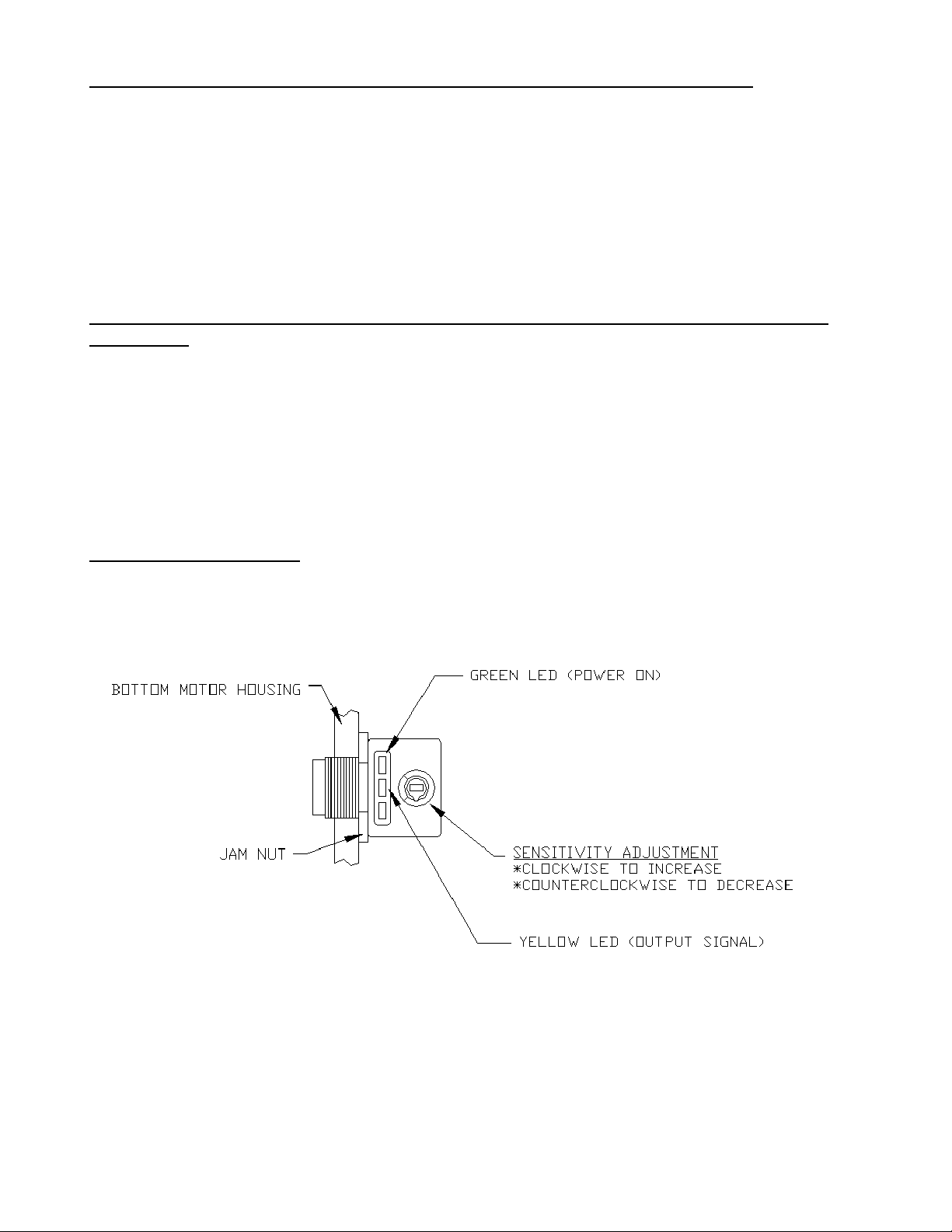
ROTATION DETECTOR (Refer to Fig. 3)
The rotation detector is a PNP diffused mode photoelectric sensor mounted in the bottom
motor housing of the machine. It senses rotation by emitting light toward a
Fig. 3. Rotation detector
notched cylinder attached to the bottom of the rotor and sensing the amount of light reflected
back. The sensor’s sensitivity is set at an optimum level at the Barrett factory. It should not
require adjustment. However, if it seems to be malfunctioning, check the following:
#0-313A-SBA (6/01)
Page 14 of 14 pages
BARRETT CENTRIFUGALS INC.
1-800-228-6442
The sensor must be secured to the motor housing by the jam nut.
The green LED on the sensor should be lit, indicating that it is receiving power.
To adjust the sensitivity turn the sensitivity adjustment potentiometer, with a screwdriver,
all the way in the clockwise direction.
With the machine’s lid open, manually spin the machine’s carrier. The yellow LED on the
sensor should blink, the more speed the more rapid the blinking.
When the yellow LED stops flashing the machine is ready to run a cycle.
A flashing output signal from the sensor is interpreted by the PLC as spindle rotation. If
the drive motor coil (1M) is energized and the PLC does not receive or loses the rotation
signal the machine will immediately brake to a stop. The red light on the machine’s push
button station will illuminate to indicate a system fault. The fault signal will only reset when
the machine’s disconnect is turned off.
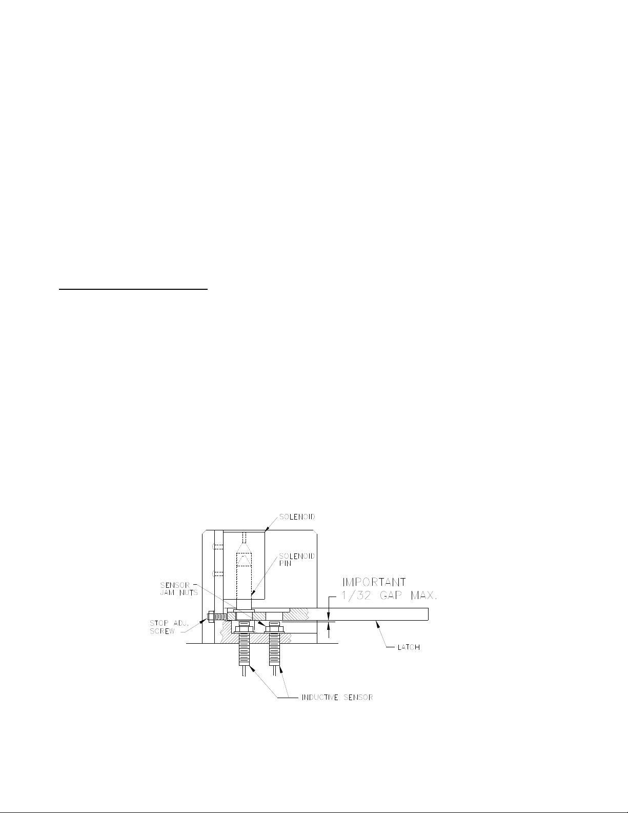
LID LATCH ADJUSTMENT (Ref. to Fig. 4)
Before any maintenance is performed on the lid latch be sure power is off and locked out. To
remove the sheet metal guard protecting the latch assembly, first remove the front cover of
the push button station enclosure. Remove the screws holding the guard in place and slide it
off of the assembly. Clean any contamination or build-up from all assembly components (use
compressed air if available). If necessary remove the solenoid pin and clean thoroughly. Be
sure the pin slides freely in the solenoid cylinder. It is very important that the pin is
aligned properly when the solenoid is fastened to the bracket.
While manually holding the pin up, slide the lever into its closed position and visually inspect
the gap between the sensor tips and the bottom surface of the latch. The gap should be
approximately 0.03 in. If not, loosen the sensor jam nuts and adjust the height by carefully
turning the sensor barrel. Be careful not to over extend the sensor tip as it could be damaged
if struck by the latch. If the sensor does not turn freely apply some WD-40 or similar lubricant
to the threads. When the sensors are adjusted properly, tighten the jam nuts to
approximately 48 inch pounds of torque.
Fig. 4. Lid latch components

#0-313A-SBA (6/01)
Page 15 of 14 pages
BARRETT CENTRIFUGALS INC.
1-800-228-6442
Check that when the lever is in the closed position the lever site hole is aligned properly with
the sensor tip and solenoid pin. If not, adjust the latch stop position by turning the stop
adjusting screw.
Be sure to replace and securely fasten the sheet metal guard and enclosure cover
when complete.
BEARINGS
The bearings in this machine are for centrifugal application having special internal fits and
should be purchased from Barrett.
REPAIR PARTS
Repair parts are available from:
Barrett Centrifugals Inc.
156 Goddard Memorial Drive
Worcester, MA 01603
Telephone: 800-228-6442 or 508-754-6891
Fax: 508-756-5342
E-mail: [email protected]
Web Site: Barrettinc.com
Be sure to specify the serial number of the machine, found either on the control panel
nameplate and / or stamped on the machine base, when ordering parts.
This manual suits for next models
2
Table of contents


