Barrett 4050 User manual

BARRETT
Operating Manual
4050 Transporter
BCM405051/1
© Barrett Communications
Head Ofce:
Barrett Communications Pty Ltd
47 Discovery Drive, Bibra Lake, WA 6163 Australia
Tel: +61 8 9434 1700 Fax: +61 8 9418 6757
Email: [email protected]
www.barrettcommunications.com.au


3
Contents
INTRODUCTION 1 .........................................................................................5
Overview ..................................................................................................6
Rear Ports - Left .......................................................................................7
Rear Ports - Right .....................................................................................8
Inside the Case .........................................................................................9
OPERATION 2 ..............................................................................................11
Internal Battery ......................................................................................11
Fitting the Battery ............................................................................11
External Battery .....................................................................................15
Mains Power .........................................................................................16
CHARGING 3 ...............................................................................................17
Solar Panel Charging ..............................................................................18
Setting the Charge Prole ................................................................18
Vehicle 12V Accessory Port Charging .....................................................20
The ARK Battery Charger ..................................................................20
DC-DC Charging ...............................................................................21
Selecting Battery Prole ...................................................................22
Charge Screen ..................................................................................23
Further Information ..........................................................................23
Mains Power Charging ...........................................................................25
Warranty Statement ....................................................................................27
Contact Details ......................................................................................28

4

5
INTRODUCTION 1
The Barrett 4050 Transporter combines Barrett 4050 HF radio equipment into
an easily transportable rugged Pelican 1560 case allowing the system to be
eld operational in minutes. There is no longer a need for time-consuming
unpacking, connecting and organising that can be impractical in emergency
situations. Instead, simply attach the appropriate antenna and the Barrett 4050
Transporter is HF transmission ready.
The system is designed to be compatible with multiple power and charging
sources including internal and external DC batteries and AC mains power. The
internal battery can be charged from multiple sources including the 12V DC
cigarette lighter/accessory output from a vehicle, and Barrett Rapid Deployment
Solar Panels (P/N BCA209010). Power is automatically switched, in a prioritized
manner, between the AC and DC sources. An internal 7 Amp multi-prole
AC-DC/DC-DC battery charger keeps the internal and/or external battery ready
for use whilst AC power is available or connected to vehicle DC outlet. This
internal charger also displays battery status information.
Charging is also available via the onboard Victron SmartSolar charge regulator
congurable via bluetooth and a convenient smartphone application.
For operational information on the following, please consult the appropriate
operational manual:
Barrett 4050 HF SDR Transceiver - Barrett 4050 HF SDR Transceiver Operating
Manual (P/N BCM40500)
Longwire throw-out broadband dipole antenna
HF Radio Digital Voice and Secure Digital Voice manual (P/N BCM40504)
4000 Series IP Connectivity/Networking Guide (BCM40507)
Barrett ALE 2G and 3G User Guide (P/N BCM40524)
Internal Battery should be disconnected when not in
use or being transported by road or air.
Disconnect mains power before attempting any
installation/maintenance on the 4050 transporter.
6
1
2
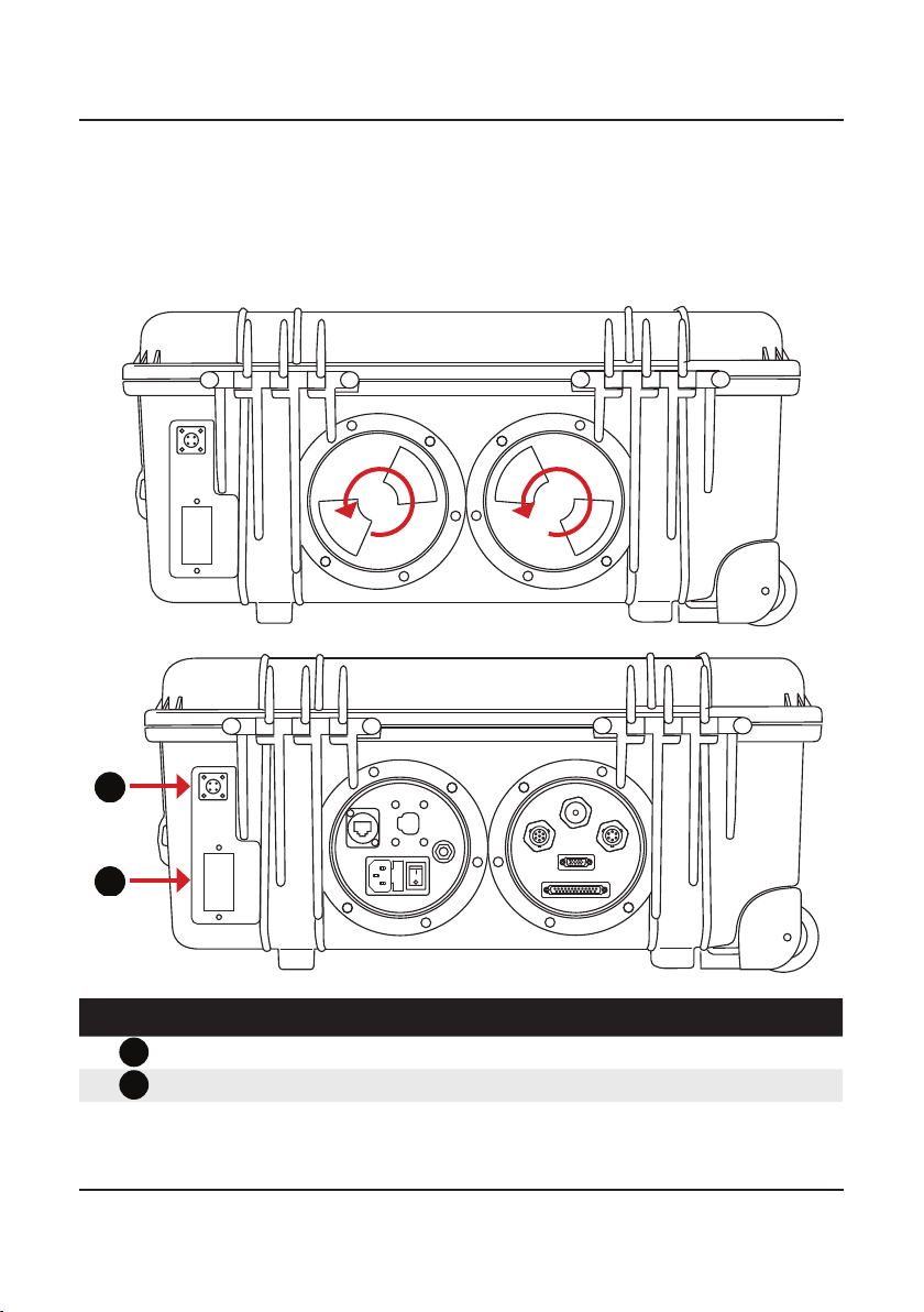
Overview
The rear ports of the 4050 Transporter have been designed for optimal connec-
tor protection without compromising quick and easy access.
To access the connectors, turn the lids anti-clockwise and remove.
Reference Description
1
Solar panel input (Barrett solar panel only P/N BCA209010)
2Anderson connector input for external battery

7
Rear Ports - Left
Reference Description
1Ethernet connection
2Mains AC power connection (includes AC fuse and on/off switch)
3
DC In from vehicle DC accessory outlet (cig. lighter socket)
4
Earth (ground) stud
1
2
3
4

8
Rear Ports - Right
Reference Description
1Antenna In
2
ATU connector
3GPS Connector
4
Remote Head connector (DB-15)
5Accessory connector (DB-25)
1
2
3
4
5
9
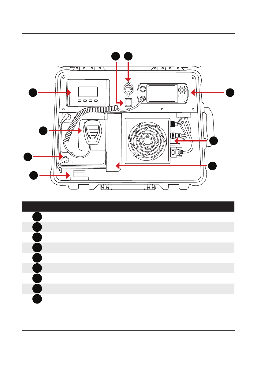
Inside the Case
Reference Description
1ARK AC-DC Battery charger
2Solar and DC/DC charging switch
3Resettable circuit breaker (Battery isolator)
44050 transceiver control head
54050 hand microphone and clip
6
DC Battery
7Internal/External connection for DC power
84050 transceiver body with fan unit
9Battery hold-down bracket
1
2
3
4
5
6
7
8
9

10

11
OPERATION 2
The 4050 Transporter can be powered by one of three means:
• Internal battery
• External Battery
• Mains power
This chapter outlines the set-up and powering of the Barrett 4050 Transporter.
Internal Battery
It may be necessary to install or change the internal battery to be suitable for
specic circumstances. It is recommended to do this before any emergency
situations take place to provide quick and efcient mobilisation when they do
occur.
WARNING: DISCONNECT MAINS POWER BEFORE ATTEMPTING ANY INSTAL-
LATION/MAINTENANCE ON THE 4050 TRANSPORTER.
THE TRANSCEIVER MUST BE REMOVED BEFORE THE BATTERY CAN BE
INSTALLED.
To remove the transceiver, disengage the circuit breaker and disconnect all rear
cables. Hold down the two black tabs on the right hand side of the transceiver
mounting plate while slightly lifting the transceiver. Pull the transceiver to the
right and then up to release it. Disconnect the remote head L-shaped connector
on the front of the transceiver.
Fitting the Battery
The battery hold-down system
has been designed to t a variety
of battery sizes. Please follow the
steps below to t a battery.
1. Check circuit breaker is dis-
engaged i.e. the red button
pressed and the yellow lever
in a downward position.
12
3. Connect positive and negative
battery leads to the appropriate
terminals and slide the battery
into position. Ensure the battery
is sitting beneath the L-shaped
brackets on the left-hand side of
the case and the battery cable is
loosely under the brackets.
4. Ensure the battery rod is in posi-
tion and put the battery hold-
down bracket in place. NOTE:
the battery rod has two available
positions on the left of the case
by moving the retaining saddle
up or down. Select the position
that allows the battery rod to be
angled downwards slightly i.e so
the lowest point of the rod is on
the left.
5. Insert the two supplied setscrews
into the appropriate holes in the
battery hold-down bracket so
that they pass through the cor-
responding slots in the vertical
panel.
2. Remove the seven cap-head
Allen screws from the top of
the display panel with an no.
2 (metric) Allen key.

13
6. Lift the display panel enough to hold the securing bracket (below left)
so that the set-screws from the previous step line up with the threaded
inserts. Loosely secure the set-screws into the securing bracket.
7. Push the battery hold-down
bracket (and battery) tight
against the left-hand side of
the case. Hold in position and
tighten the set-screws the rest
of the way. CAUTION: Do not
over-tighten.
8. Fit the supplied washers and spacers largest to smallest, with the wingnut
last. Tighten until just secure. DO NOT OVERTIGHTEN THE WINGNUT.

14
9. Plug in the Anderson connec-
tor.
10. Reconnect the VGA cable to
the front of the transceiver and
lock transceiver body back into
the mounting plate.
11. Replace rear cables and engage the circuit breaker. Internal DC battery
power is now available to the transceiver.
When circuit breaker is engaged, power will automatically be supplied to the
transceiver i.e. the transceiver will be live.
15
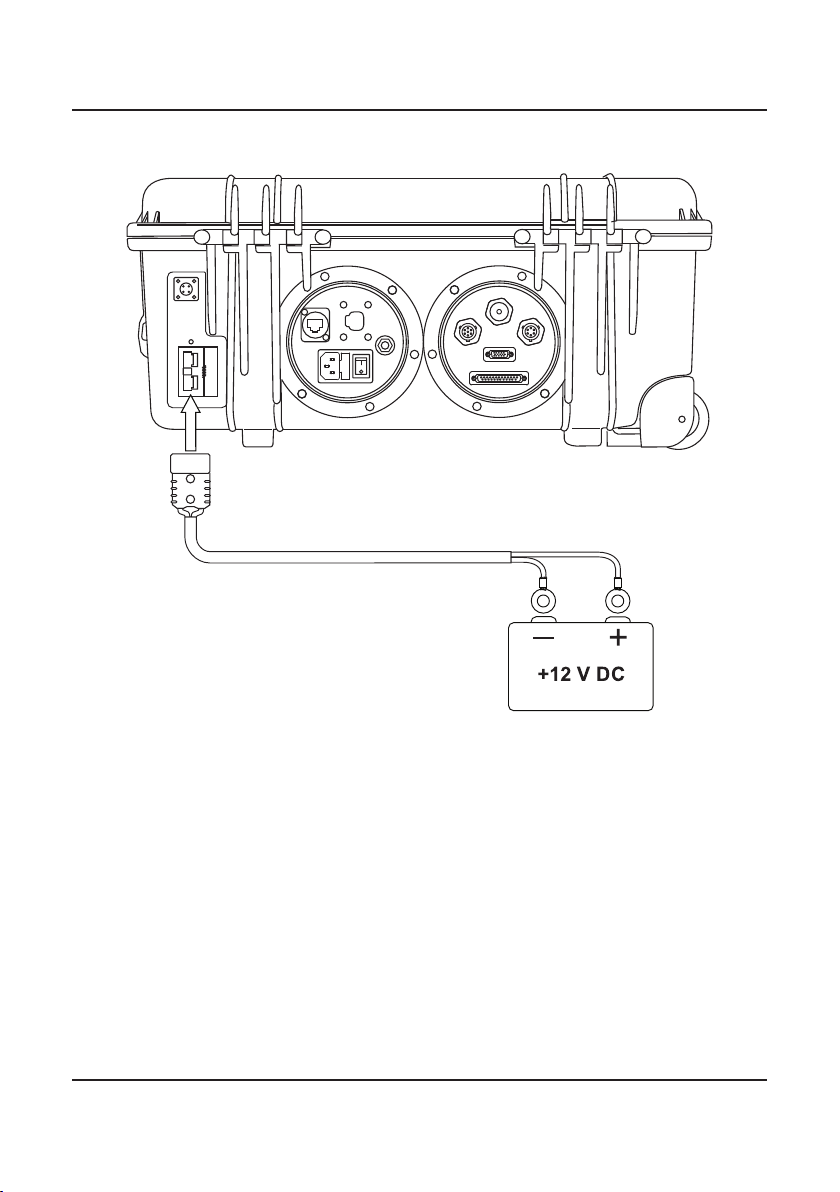
External Battery
To power the 4050 Transporter by external battery follow the below procedure:
1. Disengage the circuit breaker
2. Disconnect the internal battery by reversing step 9 of the previous section.
3. Connect the red and black ttings to the appropriate terminals on the
external battery.
4. Connect the Anderson plug to the connector on the rear of the case as
indicated above.
5. Connect the second Anderson cable on the inside of the case to the Inter-
nal/External connection for internal DC power (DO NOT RECONNECT THE
INTERNAL BATTERY)
6. Power on the 4050 transceiver.

16
Mains Power
To power the 4050 Transporter by mains power, follow the below procedure:
1. Connect the power plug to the socket in the left rear port of the case.
2. Flip the switch next to the connection
3. Power on the 4050 transceiver.

17
CHARGING 3
The internal battery can be charged by multiple means:
• Solar panels via onboard solar charge regulator
• DC vehicle power (via the vehicle’s 12V Accessory port/cigarette lighter) via
AC-DC Battery charger
• AC Mains Power via AC-DC Battery charger
The external battery can be charged as per the above however, it is important
to note that the correct proles and parameters must be set for the specic
battery being used.

18
Solar Panel Charging
The 4050 Transporter has an inbuilt solar charge regulator (a Victron SmartSolar
Charge Controller MPPT100/15). It is installed inside the control panel enclosure
and can be operated via bluetooth connectivity.
Setting the Charge Prole
It is very important to set the correct
charge prole for on the charge con-
troller for the type of battery installed.
Not doing so may result in damage to
the battery.
It is recommended to check the set
charge prole regardless of whether
the 4050 Transporter has been sup-
plied with or without an internal bat-
tery.
1. Download the Victron Connect
app from https://www.victrone-
nergy.nl/support-and-down-
loads/software/, the App Store or
Google Play.
2. Turn on device bluetooth.
3. Open App.
4. Select the Victron SmartSolar
MPPT100/15 charger from the
Device List.
5. Input temporary PIN “000000”.
The solarcharge regulator should
now be connected to the mobile
device.
6. Use the App settings section to
select the correct charge prole
for the battery being used.

19
Ensure that the Barrett solar panels are placed in full sun.
1. Connect solar panel cable to the solar charger port on the rear of the case
as shown above.
2. Flip the red internal switch to Solar Charging

20
Vehicle 12V Accessory Port Charging
The ARK Battery Charger
Reference Description
LCD Screen
Power and info button
OK button
Down button
Up button
Other manuals for 4050
1
Table of contents
Other Barrett Transceiver manuals

Barrett
Barrett HF SDR 4000 Series User manual

Barrett
Barrett 4050 HF SDR Specification sheet

Barrett
Barrett 2000 Series User manual

Barrett
Barrett 950 HF SSB Specification sheet

Barrett
Barrett 2090 Specification sheet

Barrett
Barrett 550 User manual

Barrett
Barrett 4050 HF SDR User manual

Barrett
Barrett PRC-4090 Specification sheet

Barrett
Barrett 4050 HF SDR Specification sheet

Barrett
Barrett 900 Series User manual


