Barrett 2000 Series User manual

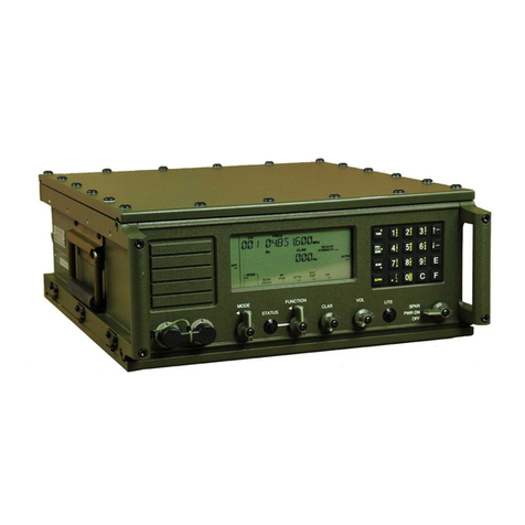
Barrett 2050 HF Transceiver
Barrett 2040 Manpack adaptor - Barrett 2055 HF Receiver
BCM20000/3 - © Barrett Communications
www.barrettcommunications.com.au
Head Office: European Office: The Americas Office:
Barrett Communications Pty. Ltd. Barrett Europe Ltd. Barrett USA LLC
8-10 Port Kembla Drive 19 Lenten Street 5676 Widmer Street
Bibra Lake, Western Australia, 6163 Alton Shawnee
P O Box 1214, Bibra Lake, Western Australia, 6965 Hampshire GU34 1HG Kansas 66216
AUSTRALIA UNITED KINGDOM UNITED STATES OF AMERICA
Toll free number (within Australia) 1800 999 580
Telephone: +618 9434 1700 Telephone: +44 1420 542254 Telephone: +1 913 322 6231
Facsimile: +618 9418 6757 Facsimile: +44 1420 543373 Facsimile: +1 913 273 0779
Web Site: www.barrettcommunications.com.au

2
Specification........................................................................................................................5
General Specifications...............................................................................................................5
Receiver Specifications .............................................................................................................6
Transmitter Specifications .........................................................................................................7
Barrett 2040, Barrett 2050 compliance..............................................................................8
FCC RF exposure compliance statement..................................................................................8
FCC RF exposure warning ........................................................................................................9
FCC modulation modes .............................................................................................................9
Industry Canada modulation modes ..........................................................................................9
Introduction.......................................................................................................................11
The use of DSP in the receiver ...........................................................................11
The use of DSP in the transmitter .......................................................................11
Other refinements................................................................................................11
Overview............................................................................................................................12
Control Head............................................................................................................................12
Microprocessor/ RF Audio PCB...............................................................................................12
Microprocessor section .......................................................................................12
RF section ...........................................................................................................12
Power amplifier PCB................................................................................................................13
Technical description.......................................................................................................14
Microprocessor / RF PCB – microprocessor section...............................................................14
Reference oscillator 22.7275 kHz .......................................................................14
Microprocessor....................................................................................................14
DDFS and VCO...................................................................................................14
VCO.....................................................................................................................14
Phase detector ....................................................................................................14
VCO divider ratio .................................................................................................15
Selcall (if enabled)...............................................................................................15
Audio mute ..........................................................................................................15
Audio Filtering .....................................................................................................15
Noise reduction ...................................................................................................15
Microprocessor / RF PCB – RF section...................................................................................15
First mixer............................................................................................................16
Post mixer amplifier Q5.......................................................................................16
First IF filter F1, F2 ..............................................................................................16
Second mixer U48...............................................................................................16
455 kHz IF amplifier ............................................................................................17
AGC.....................................................................................................................17
Carrier insertion generator ..................................................................................17
Third mixer (Product detector) ............................................................................17
Speaker output ....................................................................................................17
Tones ..................................................................................................................18
Transmit ...................................................................................................................................18
Microphone input. Remote head / Front Panel ...................................................18
Line input.............................................................................................................18
Microphone / Line input selection........................................................................18
Compression .......................................................................................................18
Transmit tones.....................................................................................................19
Post DSP (Transmit direction).............................................................................19
455 kHz IF processing.........................................................................................19
Second mixer ......................................................................................................19
First mixer............................................................................................................19
Noise blanker ......................................................................................................19
Power amplifier (PA) PCB .......................................................................................................20
Gain control amp .................................................................................................20

3
Relays .................................................................................................................20
Low pass filters....................................................................................................20
ALC control..........................................................................................................20
Over-voltage and reverse voltage protection ......................................................21
Auxiliary antenna socket .....................................................................................21
Receiver RF amplifier..........................................................................................21
Control head - front panel ........................................................................................................22
Microphone - Speaker.........................................................................................22
Maintenance......................................................................................................................23
Introduction ..............................................................................................................................23
Opening the 2050 for PCB access......................................................................23
Opening the 2040 for PCB access......................................................................27
Printed Circuit Board (PCB) maintenance...........................................................30
Component replacement.....................................................................................30
CMOS devices ....................................................................................................30
Transmitter power amplifier maintenance precautions .......................................31
Fault diagnosis..................................................................................................................32
General ....................................................................................................................................32
Specific faults...........................................................................................................................32
Transceiver will not power up..............................................................................32
After power up the “Barrett logo” screen stays on. .............................................33
Transceiver will not receive but displays OK ......................................................33
No receiver noise ................................................................................................33
Receiver noise present, but does not receive.....................................................33
Main microprocessor faults .................................................................................34
VCO faults ...........................................................................................................34
Transmitter faulty.................................................................................................34
Expected signal levels .............................................................................................................35
Adjustments......................................................................................................................37
Front panel...............................................................................................................................37
Master oscillator frequency adjustment ...................................................................................37
Microprocessor/ RF Audio PCB...............................................................................................37
VCO frequency adjustment .................................................................................37
45MHz IF Filter....................................................................................................38
Power amplifier (PA) PCB .......................................................................................................38
Driver bias setup .................................................................................................38
Power Amplifier (PA) bias setup .........................................................................39
Software options...............................................................................................................40
Internal jumper settings ...................................................................................................40
Internal PCB options ........................................................................................................40
Pactor III Modem......................................................................................................................40
Clover 2000 modem ................................................................................................................40
Features and configurations unique to transceiver models.........................................40
Barrett 2050 receivers .........................................................................................40
Barrett 2040 Manpack Adaptor........................................................................................41
Base PCB ................................................................................................................................41
Front Panel PCB......................................................................................................................41
Internal charger PCB ...............................................................................................................42
Specifications ......................................................................................................42
Automatic antenna tuner PCB .................................................................................................43
Introduction..........................................................................................................43
Tuning Network ...................................................................................................43

4
Pad and Phase Detector .....................................................................................43
Current Sense .....................................................................................................43
Impedance transformer .......................................................................................43
Microprocessor....................................................................................................43
Tuning Algorithm .................................................................................................44
Specifications ......................................................................................................44
Rear panel connectors.....................................................................................................45
Auxiliary connector ..................................................................................................................46
GPS connector.........................................................................................................................47
Fan connector ..........................................................................................................................47
Automatic antenna...................................................................................................................47
Power connector......................................................................................................................47
Circuit diagrams and overlays.........................................................................................48
2050 transceiver ......................................................................................................................48
2040 manpack adaptor ............................................................................................................48
Parts lists...........................................................................................................................49
2050 transceiver - Micro Processor / RF PCB.........................................................................49
2050 transceiver - Power Amplifier PCB .................................................................................63
2050 Transceiver – Front panel PCB ......................................................................................69
2050 Transceiver – Rear panel PCB.......................................................................................69
2050 transceiver - Control head and display transition PCB’s ................................................70
2050 transceiver - Control head transition PCB ......................................................................73
2040 Manpack adapter - Front Panel PCB..............................................................................74
2040 Manpack adapter - Base PCB ........................................................................................76
2040 Manpack adapter – Automatic antenna tuner PCB ........................................................77
2040 Manpack adapter – Internal charger PCB ......................................................................79

5
Specification
Using measurement methods described in ETS 300-373.
General Specifications
Equipment BARRETT 2050 transceiver local (desk top) and remote (trunk mount) configurations.
Standards Exceeds/complies with Australian/ New Zealand standard
AS/NZS 4770:2000 and AS/NZS 4582:1999
Exceeds/complies with European standard ETSI 300 373 and associated Amendment A
Exceeds/complies with EMC and vibration standard IEC 945
Complies with MIL Spec. 810 F for drop, dust, temperature, shock and vibration.
FCC approval number 2050:- OW4-BARRETT2050HF
Industry Canada approval number 2050:- 6468A-2050HF
FCC approval number 2040 configuration:- OW4-BARRETT2040HF
Industry Canada approval number 2040 configuration:- 6468A-2040HF
Transmit frequency range 1.6 MHz to 30 MHz (continuous)
2 MHz to 29.1 MHz (continuous) USA and Canada
Receive frequency range 500 kHz to 30 MHz (continuous)
Channel capacity Up to 500 programmable channels (simplex or semi-duplex)
Frequency resolution 10 Hz program mode 1 Hz tunable receiver
Frequency stability ±10 Hz or better than 0.3 PPM over temperature range - 30°C to +
70°C
Intermediate frequencies 45 MHz and 455 kHz (double conversion)
Operating modes J3E (USB, LSB) - H3E (AM) - J2A (CW) - J2B (AFSK)
Optional J2B (AFSK) with narrow filter.
Note:- Only J3E (USB) available in USA and Canada
Operating temperature -30°C to +60°C (-35°C to +70°C at reduced specification)
Humidity 95% relative, non-condensing
Display system Super-twist backlit LCD graphics display 128 x 64
Controls 23 key keypad - illuminated
Programming interfaces Infrared (IrDA) and RS-232
Supply voltage 13.8V DC + 20% / - 10% (negative ground) Polarity protected. Over
voltage protected.
Current consumption 470mA receive (muted, back lighting off)
Antenna impedance 50 Ohms unbalanced
Weight 2050 local control configuration 2.58Kg.
2050 remote (trunk mount) configuration, main unit 2.36Kg.
2050 remote (trunk mount) configuration, control head 0.22Kg

6
Dimensions 2050 local control configuration
185mm W x 270mm D x 70mm H
2050 remote (trunk mount) configuration, main unit
185mm W x 235mm D x 70mm H
2050 remote (trunk mount) configuration, control head
185mm W x 33mm D x 70mm H
Selcall system Based on CCIR 493-4, four and six digit systems. Protocol available
for free distribution. Also true CCIR standard and other manufacturer’s
emulation.
Scan types Selcall, Voice (syllabic), AGC derived signal level.
Scan channels 8 scan tables, each with up to 30 channels.
Scan rate Selcall Scan - Fixed at 500ms.
Non Selcall scan - Adjustable from 100ms to 5 secs.
Switching speed Less than 15mS Tx to Rx, Rx to Tx
Receiver Specifications
Sensitivity -120dBm (0.224µV) for 10dB SINAD - J3E Mode pre-amp on
-115dBm (0.398µV) for 10dB SINAD - J3E Mode pre-amp off
-110dBm (0.708µV) for 20dB SINAD - J3E Mode pre-amp on
-105dBm (1.260µV) for 20dB SINAD - J3E Mode pre-amp off
Selectivity J3E -1 kHz and + 4 kHz better than 50dB
-2 kHz and +5 kHz better than 55dB
-5 kHz and +8 kHz better than 60dB
Selectivity J2B (opt.) -500 Hz and + 500 Hz better than 60dB
The level of an unwanted signal above the level of a wanted signal
that will reduce the SINAD of the wanted signal from 20dB SINAD to
14dB SINAD
Blocking (MUS) -20 kHz and +20 kHz better than 71dB
The level of an unwanted signal above the level of a wanted signal
that will reduce the SINAD of the wanted signal from by 6dB or cause
and output level change of 3dB.
Blocking (+60dbuV) -20 kHz and +20 kHz better than 60dB (+110dBuV)
The level of an unwanted signal above the level of a wanted signal
that will reduce the SINAD of the wanted signal from by 6dB or cause
and output level change of 3dB.
Intermodulation better than 89dbµV
The level of two unwanted signals, that are within 30kHz of the
wanted signal, above the level of a wanted signal that reduces the
SINAD of the wanted signal to 20dB.
Spurious response ratio Better than 70dB
Reciprocal mixing Better than 105 dBµV
In-band IMD Better than 34dB

7
Clarifier range Receive only 1Hz steps up to ±1kHz (dependant on configuration).
AGC efficiency Range - less than 6.0 dB variation with an input signal producing 20dB
SINAD max usable sensitivity level to a signal 70dB above that.
AGC efficiency Increase in SNR - Increasing the input signal level 20dB from the
20dB max usable sensitivity level increases the SINAD by at least
15dB to greater than 35dB.
Audio Output 4W into 4 Ohms, 2W into 8 Ohms at less than 5% distortion
Audio output impedance 2 to 80 Ohms
Audio response Less than 6dB variation from 350Hz to 2700Hz
Audio distortion Less than 2% at rated power J3E mode
Input protection Better than 30V RMS from a 50 ohm source
Transmitter Specifications
RF output power 100 watt PEP two tone ± 1.5dB
125 watt PEP voice ± 1.5dB
or
25 watt PEP two tone ± 1.5dB
30 watt PEP voice ± 1.5dB
or
8 watt PEP two tone ± 1.5dB
10watt PEP voice ± 1.5dB
Duty cycle 100% two-tone input signal with fan option
Protection Safe under all load conditions, thermal protection against excessive
power transistor temperatures.
Sideband suppression Better than -65dB below PEP
Harmonic suppression Better than -60dB below PEP
Carrier suppression Better than -55dB below PEP
Residual hum and noise Better than -58dB
Spurious emission Better than -60dB below PEP
Intermodulation prods. Better than -32dB below PEP (26dB below two tone peak)
Audio frequency response Less than 6dB variation 350Hz to 2700 Hz
Current consumption Voice average less than 9Amps typical
Two tone less than 12Amps typical

8
Barrett 2040, Barrett 2050 compliance
Barrett 2000 series transceivers comply to the following communications standards:-
Australian / New Zealand Standard
MF and HF radio communications
Equipment in the land mobile service utilising single sideband suppressed carrier emission
AS/NZS 4770:2000
FCC Part 90
Barrett 2000 series transceivers comply to the following EMC standard:-
EN301 489-1 V 1.4.1 (2002-08)
Barrett 2000 series transceivers comply to the following electrical safety standard:-
EN60950-1:2002
FCC RF exposure compliance statement
The Barrett 2040 Manpack Transceiver and the Barrett 2050 HF Transceiver have been tested and comply
with the Federal Communications Commission (FCC) RF exposure limits for the General
Population/Uncontrolled exposure environment.
In addition, it complies with the following Standards and Guidelines:
FCC 96-326, Guidelines for Evaluating the Environmental Effects of Radio-Frequency Radiation
FCC OET Bulletin 65 Edition 01-01 (2001) Supplement C, Evaluating Compliance with FCC
Guidelines for Human Exposure to Radio Frequency Electromagnetic Fields
ANSI/IEEE C95.1-1992, IEEE Standard for Safety Levels with Respect to Human Exposure to Radio
Frequency Electromagnetic Fields, 3 kHz to 300 GHz
ANSI/IEEE C95.3-1992, IEEE Recommended Practice for the Measurement of Potentially Hazardous
Electromagnetic Fields - RF and Microwave

9
FCC RF exposure warning
To ensure optimal transceiver performance and to avoid exposure to excessive electromagnetic fields, the
antenna system must be installed according to the instructions provided.
High voltages exist on the antenna during transmission and tuning. Do not touch the antenna during these
activities. RF burns may result.
Install the grounding system or counterpoise as directed to prevent RF burns from any metal part of the
transceiver.
Safe working distance is based on continuous exposure to CW type transmissions, as set out in the ICNIRP
Exposure Guidelines (1998) for occupational exposure. Safe working distance can be reduced with normal
voice communication.
For FCC compliance, when the 2050 transceiver is used at a power level of 100 watts PEP, the
antenna(s) used with this transceiver should be located at least 3 metres from the operator and should not
be co-located or operating in conjunction with any other antenna or transmitter.
For FCC compliance, when the 2040 transceiver is used at a power level of 30 watts PEP, the
antenna(s) used with this transceiver should be located at least 1.5 metres from the operator and should not
be co-located or operating in conjunction with any other antenna or transmitter.
FCC modulation modes
Please note that J3E Upper Sideband Mode is the only modulation mode available for operation in the
United States of America.
Industry Canada modulation modes
Please note that J3E Upper Sideband Mode is the only modulation mode available for operation in Canada.

10

11
Introduction
The Barrett 2000 series transceiver has been designed to take advantage of the latest technology whilst
remaining simple in architecture and construction. Having two main PCB’s, the PA and the Micro/RF PCB
the transceiver is housed in a rugged enclosure using aluminium extrusions.
Receive current consumption has been reduced to a low 470mA and the receiver has been designed
specifically for high dynamic range by the use of digital switching mixers.
A Digital Signal Processor (DSP) and Programmable Gate Array (PGA) based microprocessor is the core of
the transceiver performing many of its functions
This technical manual covers the Barrett 2050 transceiver, the Barrett 2055 receiver, the Barrett 2050M
transceiver module and the Barrett 2040 man-pack adaptor. The receivers and transceivers have largely
identical hardware and software and only vary by function.
The use of DSP in the receiver
Extensive but sensible use of Digital Signal Processing is used in the receiver design. The received audio
signal is both switched and filtered as required by an inbuilt Digital Signal Processor. In addition, some of
the receiver audio tones, such as alarm tones and SELCALL send audio, are generated, and switched by
the DSP. This has removed the need for much of the circuitry required for the formerly complex audio
switching.
The receiver's automatic gain control time constants are also handled by the DSP. This makes possible
specialised AGC characteristics where required. For instance a "hang" AGC is standard for the 2000 series,
but other systems can be applied as required.
The DSP is also used for Selcall and ALE tone detection, Syllabic and SSL mutes generation and noise
reduction.
The use of DSP in the transmitter
The transmitter power output is entirely controlled by the DSP, from the action taken to reduce power when
a serious antenna mismatch occurs, to reducing power in the event that the temperature becomes
excessive.
The Automatic Level Control or ALC is processed by the DSP. This allowing time constants within the ALC
loop to be individually setup for a particular transmission mode.
Other refinements
The transceiver's controlling microprocessor consists of a large Programmable Gate Array, or PGA. This
guards the transceiver against standard microprocessor obsolescence.

12
Overview
All 2000 series transceivers and receivers are made up of several common building blocks and they are all
constructed in the same common chassis. The man-pack consists of a 2050 transceiver mated with a 2040
manpack adaptor which contains the battery management system, battery pack and automatic antenna
tuner. When mated with the man-pack adaptor all connections to the transceiver are through military
standard connectors.
This manual deals with each module and has a separate section describing sections of transceiver and
receiver that are unique to that transceiver or receiver.
The 2050 transceiver and 2050R receiver all have the following three modules:-
* Control Head
* Microprocessor/RF PCB
* Power amplifier PCB
The 2040 man-pack comprises the 2050 transceiver mated with the 2040 man-pack adaptor which contains
following modules described later in this manual:-
* Battery management system PCB
* Automatic antenna tuner PCB
* Connector transition PCB
* Signal transition PCB
Control Head
The control head consists of one main PCB and a 128 x 64 LCD graphic display module and a 23 key
backlit keypad. Connections for the microphone and control head cable are made by RJ-45 8 way
connectors.
The control head communicates to the main body of the transceiver using RS-232 protocol at 33.6k baud.
The control head can be operated up to 50 meters from the transceiver main body. The loudspeaker output
connector is by a 3.5 mm jack.
Programming of the transceiver can be done from the infrared port located on the lower front centre window
of the control head.
The remote head contains its own microprocessor to drive the display and scan the keyboard, but otherwise
contains no controlling intelligence.
Microprocessor/ RF Audio PCB
Microprocessor section
This section contains the PGA based micro processor, DSP which processes received and transmitted
audio, memory, Direct Digital Frequency Synthesiser (DDFS), power supplies and audio power amplifier. It
also contains all interface circuits to the rear panel connector, the control head and the RF power amplifier.
RF section
The RF section contains the receiver, the transmitter exciter and the noise blanker. The receiver employs a
double conversion superheterodyne design with a high dynamic range. All receiver signals are processed
through either a single sideband filter which has a pass band of 2.4 KHz, or in the case of FSK (F1B)
signals, through a narrow sideband filter with a pass band of 500Hz (or other optional bandwidths).

13
A product detector is used to demodulate all signals, with an envelope detector used to generate AGC
control voltage. The noise blanker employs a separate noise pulse receiver to provide raw blanking pulses
which are manipulated in the main processor to form effective blanking pulses on the noise blanker gate.
There is a great deal of commonality between receive and transmit paths in both the R.F. and audio circuits.
Power amplifier PCB
The PA PCB raises the power level from the RF section of the microprocessor board, to 10 W, 25 W, or 125
W PEP depending on the power setting or whether the transceiver is mated with the 2040 manpack
adaptor.
Seven low pass filters provide harmonic rejection over the full frequency range, reduce receiver LO
radiation and enhance image rejection in the receiver. The PA PCB also contains the power protection
circuitry guarding against over-voltage, and reverse voltage supplies.
A VSWR bridge generates representative voltages for forwards and reverse power measurements which
tell the DSP the condition of the PA’s load. From these two signals the DSP sets the power of the PA. DSP
either sets the PEP or to reduces overall power in the event of a bad load.

14
Technical description
Microprocessor / RF PCB – microprocessor section
This PCB is divided into two separated sections. The first section contains the microprocessor, DSP and
frequency synthesizer. The synthesiser provides the stable first local oscillator source, the DSP generates
and demodulates SELCALL and ALE signals, provides functions such as the audio syllabic mute, additional
audio filtering, noise reduction and transmitter power control. This section also contains all but one of the
voltage regulators for the transceiver. Most of the regulators are switch mode types which have high
efficiency.
The second section of the microprocessor / RF PCB comprises the radio receiver, consisting of an input
30MHz low pass filter, first mixer, first IF on 45Mhz, second mixer, second IF section on 455kHz, and the
product detector. Most of the receiver system is reversed in transmit mode to form the exciter.
Reference oscillator 22.7275 kHz
The reference oscillator at 22.7275 MHz is the master clock which determines the frequency and timing of
all other synchronous events in the transceiver. It consists of sub miniature digitally temperature
compensated crystal oscillator X1, JFET amplifier Q1 and logic level translator, Schmitt trigger U55. This
gives a 3Volt peak to peak CMOS compatible square wave. The second local oscillator is exactly twice that
of the reference oscillator, and is derived from a frequency doubler inside the microprocessor U1. The exact
operating frequency of oscillator X1 differs slightly from unit to unit. During factory calibration each
microprocessor is loaded with the offset and an algorithm takes care of the compensation required.
Microprocessor
The microprocessor is a large programmable gate array (PGA) U1, and is configured as a microprocessor
by a program stored in flash memory U44
DDFS and VCO
The synthesiser employs a Direct Digital Frequency Synthesiser U13. This synthesizer has a built in DAC
which saves on external support components. The frequency data is loaded over the DDFS data bus and
the synthesiser is used to generate 1/10 of the VCO (first local oscillator) frequency.
VCO
A push pull oscillator is formed by JFETS Q13 and Q14. This is a low noise format because the FETs
spend most of the time either on or off. The oscillator is voltage tuned by Varicap diodes D6 to D9. The
tuning inductor is L25 which is slug tuned to allow the oscillator to tune between 45 and 75 MHz. The
oscillator is buffered and converted to a 3 volt CMOS square wave signal with a two stage buffer U27 and
U10.
Phase detector
The output from the VCO feeds both the first mixer in the RF section and also to a frequency divider U42.
This is generally set by the microprocessor to divide by 10 to feed the phase detector U56. This is a dual D
type Flip Flop. The other input to the phase detector comes via Q2 from U12 the direct digital frequency
synthesiser (DDFS). This normally operates at 1/10 of the VCO frequency. Thus one tenth of the VCO
frequency is phase compared with that from the DDFS. The phase detector outputs feed a charge pump
formed by Q10, Q11, Q12, Q15 and surrounding parts. The charge pump pushes the loop filter input up or
down in voltage as required to keep the frequency stable. Any error is fed back to the varicap diodes via
the loop filter formed by R158, R113, R157, C157, C1578, and C155.

15
VCO divider ratio
As mentioned above, the VCO frequency divider U42 normally divides by 10, but sometimes another ratio
may be more desirable. This is because the DDFS by its very nature produces spurs at some frequencies.
Since the DDFS can produce millions of frequencies, predicting ones which will produce these spurs is not
possible. However, if the VCO divider ratio were changed, the DDFS frequency would need changing to
keep the transceiver on the same frequency. Thus in the event that a channel frequency is chosen which
produces spurs on the DDFS output, changing the DDFS frequency will solve this problem.
Selcall (if enabled)
The selective system utilises Frequency Shift Keying (FSK) as the modulation technique. The tones are
generated and decoded by the DSP. The microprocessor however processes the data for encoding and
the decoded data. The design of the encoder/decoder allows individual channels to be set for operation on
either the International and OEM Selcall format (Codan compatible, based on CCIR 493-4) or the true
CCIR493-4 format and its associated tones. Tones used are as follows:-
International and OEM Selcall format :-
High tone:- 1870 Hz Low tone:- 1700 Hz Centre tone:- 1785 Hz
CCIR 493-4 International Standard format:-
High tone:- 1785 Hz Low tone:- 1615 Hz Centre tone:- 1700 Hz
Audio mute
The DSP is used to provide three types of receiver muting. These are:-
SELCALL mute - mutes the receiver until it receives a SELCALL addressed to it.
SSL mute - mutes the receiver when signals are weaker than a set signal strength.
Syllabic mute - mutes the receiver unless speech is received.
Audio Filtering
The DSP provides additional audio filtering (beyond that given by the IF filter) as required. This extra
filtering is accessed from the front panel menu. The microprocessor sets the default amount of audio
filtering depending on the mode of operation.
Noise reduction
The DSP also implements a noise reduction mode (three selections) which is selected from the front panel.
Microprocessor / RF PCB – RF section
The RF section provides the complete exciter and receiver for the transceiver. It includes:-
First mixer
Roofing filter at 45 MHz
45 MHz IF amplifier
45 MHz Noise blanker receiver
Second mixer
Two noise blanker gates
SSB filter and optional other types
Envelope detector for AM and AGC
Product detector for SSB,FSK and CW signals
T-R switching

16
The RF section has a common RF input and output port and separate audio input for Tx and output for Rx.
A double superheterodyne system is used, with a first IF of 45 MHz and second IF at 455 kHz. Three
oscillator injection frequencies are used, LO1 at (Carrier frequency + 45 MHz), LO2 at 45.455 MHz and LO3
or the Carrier Insertion Oscillator at 453.4kHz on USB and 456.6kHz on LSB. There is a separate 45 MHz
receiver to generate gating pulses for the noise blanker.
The audio section of the RF/Audio PCB implements some frequency tailoring. The audio is further
processed and filtered as required by the digital signal processor or DSP before being fed to the audio
power amplifier. Both of these are located on the microprocessor section of the PCB.
First mixer
Signals from the antenna are fed to the 30 MHz low pass filter, L14, L15, L41 and associated Capacitors.
This minimises the image response in both receive and transmit directions. It also serves to limit LO1
breakthrough. High frequency transformer T2 splits the signal into two phases (0 and 180degrees) to feed
the high level balanced mixer U47, which is in fact a high speed analogue MOS FET bus switch. The
centre tap on the transformer also facilitates the application of the bias required by the mixer. The action of
mixer U47 under control of the first local oscillator signal (LO1 a CMOS level square wave) is to switch pin 4
of U47at the local oscillator rate between its pins 3 and 1, thus switching a two phase sample of the input
signal from transformer T2 to the mixer output at pin 4. This results in sum and difference products which
are fed to the first of two noise blanker switches U51. The operation of the noise blanker is described in a
later paragraph. The local oscillator signal is suppressed by the first mixer. The mixer output passes
through a direction reversing transmit receive (TR) switch U53 to the post mixer amplifier Q5.
Post mixer amplifier Q5
The purpose of the post mixer amplifier is three-fold. Firstly, it supplies a broad band termination to the first
mixer so as to minimise unwanted products from it. Secondly it supplies some gain to overcome the loss of
the first mixer but only sufficient to minimise its overload in the presence of strong unwanted signals.
Thirdly, in combination with the attenuator formed by resistors R142 to R144, it provides a flat impedance
match to the 45 MHz roofing filter F1, which follows another TR switch U54. Note that the TR switches and
the mixers are all of the same part type, a versatile CMOS analogue bus switch NCSB3157. This is an
analogue change over switch for signals in the range of zero to +5 volts. It will also switch digital signals in
that range.
First IF filter F1, F2
The first IF filter removes the unwanted high frequency products generated by the first mixer. This filter has
a bandwidth of about 6 kHz, and consists of two matched crystal filter units F1 and F2. These are matched
to 50 ohms in and out by L networks C183, L20 and C182, L19 respectively. These filters are tuned in the
factory before being linked to their input and output ports by soldering across links SP1 and SP2. Test
points TP1 and TP2 are used at the factory to connect the filters to a spectrum analyser and tracking
generator for tuning.
The 45MHz crystal filter is terminated via T-R switch U50 by the input of amplifier Q3. The stage gain is
about 12dB and is kept low because although the 45MHz filter removes most of the unwanted first mixer
products, it may still allow signals to pass which are close to or adjacent to the wanted signal. If any off
these are very large, they may still overload this amplifier if it had too much gain. This amplifier also isolates
the 45 MHz filter which is sensitive to its termination impedance.
Second mixer U48
This is a duplicate of the first mixer, but in this case converts the 45 MHz down to 455 kHz. The conversion
oscillator signal is LO2 which is on 45.455 MHz. Transformer T3 provides the phase splitting for the input
signal and R39 provides the mixer bias via the transformer centre tap. This mixer, like the first also
generates unwanted output products. The mixer output impedance (and thus voltage) is stepped up from
50 ohms to 1800 ohms by the 36:1 ratio transformer T1. This matches the characteristic input impedance
of the 455 kHz filter. Immediately preceding this filter is the second noise blanker switch U40. The noise

17
gates are controlled by signals from the microprocessor. These are NOISEGATE 2 on U40 and
NOISEGATE1 on the first noise gate U51. The receiver comes with a filter F9 fitted as standard. However,
either a narrow filter, F4 or one of two other special purpose filters can be fitted instead. The required filter
is selected by analogue bus switches U35 and U36.
455 kHz IF amplifier
The filtered signal feeds a two stage high gain AGC controlled amplifier using depletion mode dual gate
MOSFETs Q8 and Q9. The AGC control voltage comes from the DSP. The drain load 1mH inductors L17
and L18 are broadly tuned to 455kHz with C108 for L17 and C109, for L18. The output voltage swing can
be quite high at around 10 volts peak to peak on a strong input signal. This is sufficient to overload the
following product detector an AM envelope detector. The output level is made more manageable by splitting
Q9 output tuning Capacitor into a voltage divider with C253 and C254. This output feeds both the envelope
detector Q7 which is biased as a rectifier, and the product detector (U52 and U57).
AGC
The envelope detector, transistor Q7 is the AGC rectifier. The output is taken from the emitter of Q7 via the
resistor R179. This is shown as the SSL line on the RF audio section of the schematic. The SSL signal is
then processed by the DSP. The AGC characteristics are controlled by the DSP. The returned AGC signal
from the DSP is applied to the MOS FET's Q8 and Q9 gain control gates.
Carrier insertion generator
The transmit and receive Carrier Insertion generators are used to produce CIO Tx and CIO RX, whose
frequencies are dependant on the type of IF filter used, and the mode of operation chosen but is in the
region of 455 kHz. Theses are generated directly by the microprocessor U39 and are CMOS level square
waves.
Third mixer (Product detector)
This is a high level circuit around U62 and U57B, and IF signal is switched by the carrier re insert signal
CIO-RX. This mixer works in a different way to the previous mixers. In this mixer the output voltage from
the IF amplifier is converted to a current in R32. This current is either shunted to ground via C90 or into the
summing junction (virtual ground) at the input of U57B. Capacitor C179 filters the unwanted IF component
of the signal. R32 also acts as a dissipating load for this part of the signal. The low value resistor R110 is
to keep U57B from generating high frequency noise. Extra high frequency roll off is obtained with the next
active low pass filter stage in U57A and surrounding components. This product detector has excellent low
distortion properties because the FETs in the product detector switch U62 are only switching current and
this avoids the change in resistance of the FETs with changing signal voltage levels, which can be a source
of distortion. The audio from U57A (RX AUD) is fed to the DSP U2 on the microprocessor side of the PCB,
where it is further processed as required for a particular application. The signal emerges from the DSP and
is converted back to an analogue signal by Digital to Analogue Converter U63 and it appears on OUT 3 (pin
7).
Speaker output
The audio signal emerging from the above mentioned DAC is fed to an anti-aliasing filter around U4. This is
used to remove clock frequency components from the DAC. The now processed audio passes on to half of
the dual volume control circuit U23B. This is essentially a resistor with 256 taps. The volume is controlled
by an 8 bit serial word. The control lines (SCLK and SDIN) are shown on U23A on the microprocessor
circuit diagram.
From the volume control (U32B) the signal now passes on to the audio power amplifier U19.This can deliver
2 watts into an 8 ohm load.

18
Line output
A separate audio output is taken from the DAC (OUT 2) to the line audio output level control U65B, which is
of the same type as used for the loud speaker volume control. This is part of a feed back circuit around
amplifier U6B. The output from U6B, (LINE AUD OUT) goes to the clock filter and output balancing amplifier
combination U39B and U39A. The line output emerges at the DB25 rear connector. The line level is set by
the microprocessor.
Tones
There are two sources of the various tones used in the transceiver. All of the sine wave tones for
transmission are produced in the DSP. These tones include Transmitted SELCALL tones, Automatic Link
Establishment (ALE) tones, CW tone and alarm tone transmissions.
The microprocessor produces PWM tones (U1, pin 85) for such things as key presses, SELCALL received,
and GPS detected tones. The PWM carrier is chosen such that its frequency is above human hearing and
the resultant signal is passed through an anti-aliasing filter U4B to remove the carrier products. DSP
generated tones, are also cleaned with the same anti-aliasing filter (U4B) which also resistively mixes the
two tone sources, bypassing the volume control, to the input of the speaker amplifier U19.
Transmit
Microphone input. Remote head / Front Panel
The front panel and the remote head are exactly the same unit and the two terms are used interchangeably
in this manual.
Audio from the hand held electret microphone arrives via the Front Panel interface board at connector P1
pins 11 and 12, and is amplified and converted to balanced audio in U2A and U2B on front panel PCB. The
now balanced and amplified signal leaves the front panel on connector P1, pins 5 and 6. This connector is
plugged into the small Remote Head Interface Board. From here the audio signal passes to the Front panel
Interface Board via an eight way cable with RJ45 connector at each end. This cable is a long one where the
head is used remotely or a very short cable when it is used as a front panel.
From the Front Panel Interface board the microphone audio is connected to the Microprocessor/ RF board.
Line input
Balanced line audio is fed into the 25 pin rear D connector, P1 pins 11 (BAL AUD IN 1) and 24 (BAL AUD
IN 2) on the microprocessor board. The balanced audio is terminated in a 680-ohm resistor R105 and then
it is converted to an unbalanced signal with U5A. The signal is then amplified by U5B. This stage has a line
level setting digitally controlled potentiometer U23A. The gain is set by the microprocessor.
Microphone / Line input selection
Either the microphone audio or the line audio is selected with an analogue bus switch U11. The DC outputs
of amplifiers U2A and U5B (line and microphone amplifier outputs) supply the necessary bias for the switch.
The TX SELECT line when low selects microphone audio and when high, selects line audio for
transmission.
Compression
The selected audio gets compressed with the circuit around U3 and Q1. This works in the following way.
Resistors R77, R79 and MOSFET Q1 act together as a variable Tee attenuator. When no signal is present,
the voltage gain of U3A is about 5. This amounts to 20dB. U3B is an amplifier which feeds a rectifier D2.
As the input signal level increases, U3B output causes the rectifier to generate a positive going DC voltage.
This voltage, when high enough causes the FET Q1 to start conduction. This in turn causes the signal into
the amplifier to reduce, because part of the signal is shunted to ground by Q1, and thus the output level
does not increase as rapidly as before. The net effect is that an increase in audio level of 60dB will cause

19
an output increase of only about 3dB. The level at which the onset of compression starts is set by the
voltage divider R63 and R108. The compressor output enters the DSP, U2 pin 107 (TX AUDIO) for
processing. The transmit audio data emerges from the DSP and is converted to an analogue signal in DAC
U63, and emerges from pin 12.
Transmit tones
These are the tones which are transmitted for such purposes as SELCALL, and tone for the automatic
antenna tuner. These are generated in the DSP and are summed therein with the speech signals.
Post DSP (Transmit direction)
Serial digital audio from the DSP (U2) fed to an eight channel DAC U63. The output from the DAC TX AUD
(OUT 6) is filtered off with the low pass filter around U7B on the RF audio schematic. U7A and U7B also
act as a phase splitter to feed a balanced mixer U61, an analogue bus switch. The square wave carrier, the
frequency of which depends on the selected side band (normally 453.4kHz or 456.6kHz), is fed to pin 6 of
U61. The double side band suppressed carrier output can be monitored on TP16. Bias for this stage is
supplied by R173.
455 kHz IF processing
The signal from U61 is switched to the 455 kHz crystal filter via TR switch U36B (transmit direction), and the
filter select switches U36A. Resistor R121 on the output of the mixer U61 is to present the filter with its
correct termination impedance. Since the signal level at this point is quite high, the loss in the resistor is not
significant.
Second mixer
The signal, now one side band from the filter, passes through the filter select switch U35C, impedance
matching transformer T1, and the noise gate U40 (switched through), and then to the second mixer U48.
The square wave CMOS level local oscillator LO2 is fed to pin 6 of U48. The second mixer output feeds the
45MHz filter after passing through TR switches U49 and U50. The two stage 45 MHz crystal filter removes
the unwanted mixer products.
First mixer
The now 45MHz signal is routed via TR switch U54 to amplifier Q6, and from there to the first mixer U47 via
TR switch U53 and closed noise gate U51. The first mixer’s local oscillator is a square wave with a
frequency range of 46.6 to 75 MHz. The mixer converts the 45MHz signal to the required output frequency
from 1.6 to 30 MHz. The output filter consisting of L15, L14, L41 and associated Capacitors remove the
unwanted first mixer products, leaving only the selected side band feeding the output connector P8.
Noise blanker
The noise blanker receiver U18 is fed from the first mixer output via FET Q4 which acts as a buffer and
prevents the noise blanker receiver local oscillator generating intermodulation products in the main receiver.
FM superheterodyne chip SA605, U18, is used with wide ceramic filters F6, and F7 to detect impulse noise.
The RSSI output on pin 7 produces narrow noise pulses. These are fed to comparator U30, the thresh hold
of which is set by the microprocessor (BLANKERADJ) on pin 2 of U30. When the noise pulses cross this
threshold and cause the comparator U30 to change state. This results in low going pulses (BLANKER
DETECT) which are synchronous with the noise pulses. These pulses are processed by the
microprocessor U1 to provide best timing and pulse width for optimum noise suppression. The pulses
emerge from the microprocessor on pins 137 for NOISEGATE1 and pin 136 for NOISEGATE2.

20
Power amplifier (PA) PCB
The Power Amplifier raises the power from the exciter to specified output power. It also provides harmonic
filtering for the transmitter and low pass filtering in receive mode.
Gain control amp
The signal from the exciter at a level of approx. -17dBm is fed to a gain controlled amplifier, dual gate MOS
FET Q1. The stage gain is controlled by ALC. Transistor Q10 is configured as an emitter follower to provide
buffering, gain stage Q3 raises the signal level suitable to drive the first of two push pull power amplifiers.
This pre-driver stage employs RF negative feedback via TR3, R29 and C91 to achieve low distortion.
A push-pull drive stage comprising power MOS FETS Q4 and Q5 is employed to raise the power to a level
suitable to drive the 100W power amplifier stage. The MOS FETS each require a separate bias
potentiometer, RV3 for Q4 and RV4 for Q5. Final amplification to the output level is achieved using Q12
and Q13 in push-pull. This final amplifier stage has an active bias circuit using U3B and Q2 with D2
providing a bias reference which thermally tracks the power devices due to physical contact close to the
transistors.
Relays
All of the relays in the transceiver with the exception of the PA power on - off relay RL9 are of the bi-stable
latching type. This means that they will stay operated in the SET or RESET state, even with the power
turned off until they are deliberately switched to the opposite state. They are all to be found on the PA
board. All of the relays are operated in a similar manner and an example of the operation of one relay is
given below.
Each relay has a SET and a RESET input and a common "NAME" input. For example relay RL10 has the
"NAME" of PRE AMP. To turn the pre-amp on, RL10 must be SET. Assume it starts off RESET. The
microprocessor causes the SET line, which is common to all relays to the high state (+12 volts). Then the
PRE AMP line on RL10 is put momentarily LOW. This action causes RL10 to be SET and select the RF pre
amp. Conversely, the amplifier can only be turned off or reset by taking the RESET line high and
momentarily taking the PRE AMP input low. Note that only the SET or RESET line can be taken high at
any one time, but multiple relays can be SET or RESET simultaneously
Low pass filters
Sub-octave harmonic filtering is provided by seven Cauer-Chebyshev filters with bands of 1.6 to 2.48 MHz,
2.48 to 3.84 MHz, 3.84 to 6.0 MHz, 6.0 to 9.3 MHz, 9.3 to 14.5 MHz, 14.5 to 22.48 MHz and 22.48 to 30.0
MHz. These are selected by seven bi-stable latching relays which each have one of seven filter select lines
FS1 to FS7, and common SET and reset lines. The microprocessor selects the correct filter in the manner
shown under the sub heading Relays above.
ALC control
Forward and reverse power sampling for the ALC system is implemented using current transformer TR6
and detector diodes D3 and D4. The forward and reflected voltages from the diodes (ALC1 and ALC2) are
buffered by OPAMPS U1A and U1B. Signals SWR+ and SWR- are processed by the microprocessor,
which determines attack and decay time constants, and forward power. The gain is set by the PWR ADJ
signal returned from the microprocessor. This controls the gate 2 voltage and thus the gain of MOSFET Q1.
Sometimes an external high power amplifier is connected to the transceiver. It will usually have its own
SWR Bridge and the DC voltage there from is fed to the microprocessor via pin 19 of the 26-way connector.
After processing this signal for attack and decay characteristics, the ALC signal is fed back into the PWR
ADJ line as previously mentioned.
This manual suits for next models
3
Table of contents
Other Barrett Transceiver manuals
Barrett
Barrett HF SDR 4000 Series User manual

Barrett
Barrett 2090 Specification sheet
Barrett
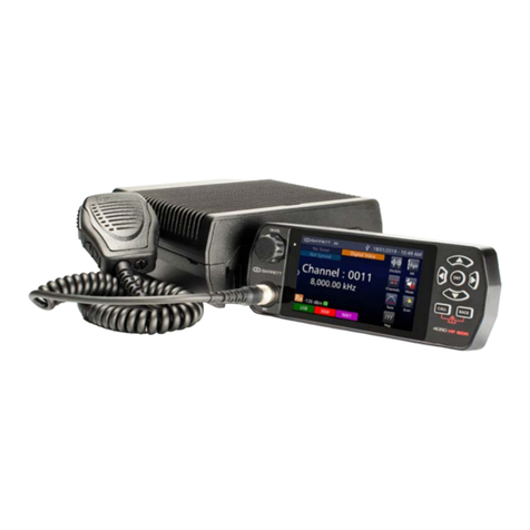
Barrett 4050 HF SDR Specification sheet
Barrett
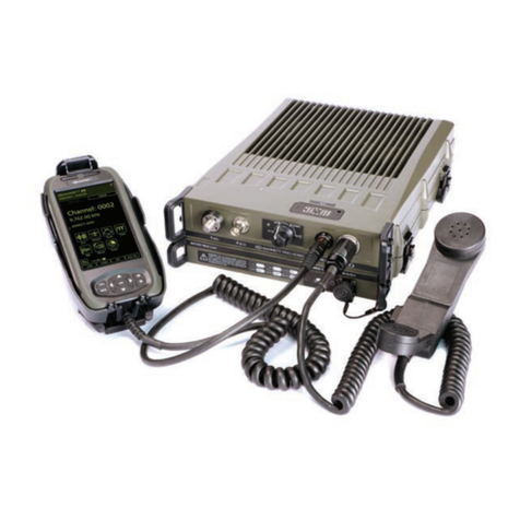
Barrett PRC-4090 Specification sheet

Barrett
Barrett 4050 HF SDR Specification sheet
Barrett
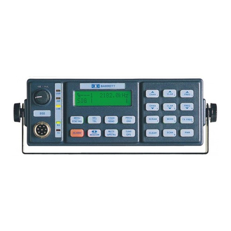
Barrett 950 HF SSB Specification sheet

Barrett
Barrett 550 User manual

Barrett
Barrett 4050 HF SDR User manual
Barrett
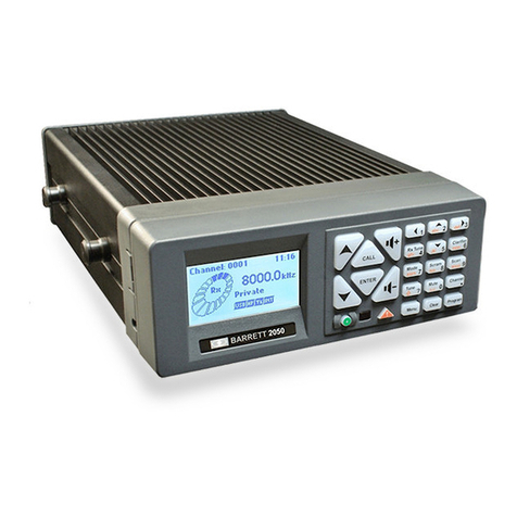
Barrett 2050 Specification sheet

Barrett
Barrett 2050 User manual

