Barrett PRC-4090 Specification sheet

Operating and Installation
Manual
Barrett PRC-4090 Tactical HF SDR Transceiver
4090-00-02/01
© Barrett Communications
s/w v1.8


iii
Compliance
Barrett 4000 series transceivers have been designed to comply to the following
communications standards:
• Australian / New Zealand Standard
• MF and HF Radio Communications.
Equipment in the land mobile service utilising single sideband suppressed car-
rier emission:
• AS/NZS 4770:2000
• FCC Part 90.
• FCC Part 87
• Industry Canada (IC) RSS-125 Issue 2
Barrett 4000 series transceivers comply to the following EMC standard:
• EN301 489-1 V 1.4.1 (2002-08).
Barrett 4000 series transceivers comply to the following electrical safety stand-
ard:
• EN60950-1:2002.
FCC RF Exposure Compliance Statement
The Barrett 4000 Series transceivers have been evaluated and comply with the
Federal Communications Commission (FCC) RF exposure limits for the General
Population/Uncontrolled exposure environment.
In addition, the transceivers have been designed to comply with the following
standards and guidelines:
• FCC 96-326, Guidelines for Evaluating the Environmental Effects of
Radio-Frequency Radiation
• FCC OET Bulletin 65 Edition 01-01 (2001) Supplement C, Evaluating Com-
pliance with FCC
• Guidelines for Human Exposure to Radio Frequency Electromagnetic Fields
• ANSI/IEEE C95.1-1992, IEEE Standard for Safety Levels with Respect to
Human Exposure to Radio Frequency Electromagnetic Fields, 3 kHz to 300
GHz
• ANSI/IEEE C95.3-1992, IEEE Recommended Practice for the Measurement
of Potentially Hazardous Electromagnetic Fields - RF and Microwave.

iv
RF Exposure Warning
To ensure optimal transceiver performance and to avoid exposure to excessive
electromagnetic elds, the antenna system must be installed according to the
instructions provided.
High voltages exist on the antenna during transmission and tuning. Do not
touch the antenna during these activities. RF burns may result.
Install the grounding system or counterpoise as directed to prevent RF burns
from any metal part of the transceiver.
Safe working distance is based on continuous exposure to CW type transmis-
sions, as set out in the ICNIRP Exposure Guidelines (1998) for occupational expo-
sure. Safe working distance can be reduced with normal voice communication.
For IC and FCC compliance, when the PRC-4090 transceiver is used at a power
level of 150 watts PEP and a 13 dBi gain antenna, the antenna(s) used with this
Transceiver should be located at least 6 metres from the operator and should
not be co-located or operating in conjunction with any other antenna or trans-
mitter.
For IC and FCC compliance, when the PRC-4090 transceiver is used in a vehicular
environment at a power level of 150 watts PEP with 1.5 dBi gain antenna, the
antenna(s) used with this transceiver should be located at least 1.6 metres from
the operator and should not be co-located or operating in conjunction with any
other antenna or transmitter.
Typical antenna types and minimum separation dis-
tance:
Antenna type Gain
(dBi)
PEP
(W)
Minimum safe sepa-
ration distance (m)
Typical
Environ-
ment
Automatic tuned and whip 0 150 1.3 Vehicle
Magnetic Loop 1.5 150 1.6 Vehicle
Multi-wire Broadband 5 150 2.4 Fixed
Log-Periodic 13 150 5.9 Fixed
Automatic tuned and Whip 0 100 1.0 Vehicle
Magnetic Loop 1.5 100 1.2 Vehicle
Multi-wire Broadband 5 100 1.8 Fixed
Log-periodic 13 100 4.4 Fixed
Automatic tuned and Whip 0 30 0.5 Vehicle

v
Antenna type Gain
(dBi)
PEP
(W)
Minimum safe sepa-
ration distance (m)
Typical
Environ-
ment
Magnetic Loop 1.5 30 0.7 Vehicle
Multi-Wire Broadband 5 30 1.1 Fixed
Log-Period 13 30 2.7 Fixed
The above antennas are identied for reference only. It is important that the
installer and operator maintain a minimum safe separation distance with the
actual antenna used in the installation and to insure, in a vehicular environ-
ment, that the transmitter is only used when persons outside the vehicle are at
least the recommended lateral distance away.
The image below shows an example of minimum recommended separation dis-
tance from antenna in a vehicular environment.
1.3 M
1.3 M
1.6 M
2019 Automatic Tuning Mobile HF Antenna
2018 Mobile Magnrtic Loop HF Antenna
Note: References to Vehicular environments and minimum safe oper-
ating distances relate to persons outside the vehicle only and not to
persons within the vehicle.

vi

vii
Contents
INTRODUCTION 1 ................................................................................1
Introduction ..................................................................................................2
Important Disclosure............................................................................. 3
Terms & Abbreviations .......................................................................... 4
The Barrett PRC-4090 HF Transceiver Overview..............................................6
BASIC OPERATION 2 ..........................................................................17
Starting the Transceiver...............................................................................18
Keypad ........................................................................................................18
Display ........................................................................................................19
Swipe Menu........................................................................................ 21
Status Info...................................................................................................23
Antenna Type ..............................................................................................24
Selecting a Channel.....................................................................................25
Making a Voice Call.....................................................................................26
Making an Emergency Call ..........................................................................27
Receiving an Emergency Call .......................................................................28
SELCALL 3...........................................................................................29
Overview .....................................................................................................30
Important Selective Calling Information......................................................31
Summary of Calling Systems .......................................................................32
Setting up a Self ID .....................................................................................33
Setting up Contacts.....................................................................................34
Additional Contact Information .......................................................... 36
Making a Selcall ..........................................................................................37

viii
Beacon Call ......................................................................................... 38
Selcall.................................................................................................. 39
Telcall .................................................................................................. 41
Advanced Call History ......................................................................... 43
Advanced Selcall Functions .........................................................................47
Selcall Settings .................................................................................... 47
Pagecall............................................................................................... 48
GPS Request........................................................................................ 49
GPS Position........................................................................................ 51
Status Call........................................................................................... 52
Secure Call .......................................................................................... 53
Hangup Call ........................................................................................ 55
Selcall Networks.................................................................................. 56
BASIC SETTINGS 4 ..............................................................................59
System Information.....................................................................................60
Head Device ID.................................................................................... 60
Serial Number ..................................................................................... 60
Version Information ............................................................................ 60
Transceiver Options............................................................................. 61
Conguration Pack Information.......................................................... 61
SDV/4026 Serial Number..................................................................... 61
General Settings..........................................................................................62
Audio Settings.............................................................................................63
Display Settings...........................................................................................64
PROGRAMMING 5 ..............................................................................65
Channel Programming ................................................................................66

ix
Programming Channels Through the Handset .................................... 66
Free Scroll Rx/Tx...........................................................................................70
Programming Via USB .................................................................................73
ADVANCED OPERATION 6 ..................................................................75
ARINC Call ...................................................................................................76
Audio - Advanced........................................................................................77
Rx Conguration................................................................................. 77
Tx Conguration ................................................................................. 77
Audio Bandwidth................................................................................ 77
Line Audio........................................................................................... 78
Line Follows Digital Voice.................................................................... 78
Line Out Level ..................................................................................... 78
Line In Level ........................................................................................ 78
Audio Record ...................................................................................... 78
Custom Filter Bandwidth .................................................................... 78
Collective Call..............................................................................................79
Digital Voice (Encoding) ..............................................................................80
Export .........................................................................................................81
Frequency Hopping .....................................................................................82
Selecting the Hopping Band................................................................ 82
Entering the Hopping PIN ................................................................... 82
Enabling and Disabling Hopping......................................................... 82
GPS Push .....................................................................................................83
GPS Push State.................................................................................... 83
Privacy Key .......................................................................................... 83
IO Settings ..................................................................................................84
RS232 Connection............................................................................... 84

x
RS232 Network Encryption ................................................................. 84
RS232 Out (async. Indications)............................................................ 84
RS232 Baud Rate................................................................................. 85
External Alarm Type ............................................................................ 85
Antenna Select Behavior ..................................................................... 85
Antenna 1........................................................................................... 85
Antenna 2........................................................................................... 85
Modes .........................................................................................................87
Mute ...........................................................................................................88
Network ......................................................................................................90
Noise Reduction (NR) ..................................................................................93
RF Settings ..................................................................................................94
Rx Preamp........................................................................................... 94
Tx Over Beep ....................................................................................... 94
Tx Timeout .......................................................................................... 95
Noise Blanker ...................................................................................... 95
Tx Power Level .................................................................................... 95
AGC Hang ........................................................................................... 95
Broadcast Filter ................................................................................... 95
Scanning .....................................................................................................96
Scan Settings ...................................................................................... 97
Secure Display Mode .................................................................................100
Security Settings........................................................................................101
Use OEM Selcall Privacy Key .............................................................. 102
OEM Selcall Privacy Key..................................................................... 102
Frequency Hop PIN............................................................................ 102
Frequency Hop Rate.......................................................................... 102
OEM Secure Type .............................................................................. 102

xi
OEM Secure Key................................................................................ 102
Secure Digital Voice/Data Key............................................................ 103
Digital Voice Baud Rate..................................................................... 103
Selcall Secure Call Hop Rate .............................................................. 103
Selcall Secure Call Code .................................................................... 103
SDV/4026 Programming Mode ......................................................... 103
Service Mode .................................................................................... 103
Enable Power On PIN ........................................................................ 104
Transceiver Lock ................................................................................ 104
Over the Air Zeroise (OTAZ)............................................................... 104
Zeroise .............................................................................................. 104
Remote Access Password .................................................................. 104
Stealth Mode.............................................................................................105
Theme Schedule ........................................................................................106
Tuning .......................................................................................................107
Zeroise ......................................................................................................108
INSTALLATION 7 ...............................................................................109
Introduction ..............................................................................................110
Installing a Secondary Control Handset.....................................................111
Manpack Installations ...............................................................................112
Control Handset Mounting ............................................................... 113
Battery Pack ...................................................................................... 114
Tactical Antenna Options .................................................................. 119
Tactical Broadband Dipole Antenna (2090-02-03)............................. 124
Tactical Tuned Wire Dipole Antenna (2090-02-01) ............................ 127
Mobile Installations...................................................................................130
PRC-4090 System Docking Station – Rear ......................................... 131

xii
Assembly........................................................................................... 132
SDS Feet Congurations.................................................................... 133
Handset Docking Station Congurations .......................................... 134
Complete Mobile Assembly............................................................... 135
2019 Automatic Tuning Mobile HF Antenna ..................................... 140
2018 Mobile Magnetic Loop Antenna............................................... 151
Base Station Installations ..........................................................................153
Assembly........................................................................................... 154
Cooling Fan ........................................................................................156
Installing the Cooling Fan ................................................................. 156
Connection Diagram ......................................................................... 157
Site Selection Recommendations ..................................................... 159
Antennas .......................................................................................... 161
912 Multi wire Broadband Dipoles.................................................... 161
4017 Automatic Tuning Horizontal Dipole Antenna.......................... 163
4011 Automatic Antenna Tuner for Base Station Installations .......... 166
Marine Installations...................................................................................179
APPENDICES 8..................................................................................184
Appendix 1 - Specications .......................................................................185
Appendix 2 - Connectors...........................................................................189
Appendix 3 - Overview of HF Operation ....................................................207
Appendix 4 - BITE Test ..............................................................................211
Warranty Statement ..................................................................................214
Contact Details.................................................................................. 215
Index .........................................................................................................216

1
INTRODUCTION 1
This chapter contains the following sections:
• Introduction
• Terms and Abbreviations
• The Barrett PRC-4090 HF Transceiver Overview

2
BARRETT PRC-4090 TACTICAL HF SDR TRANSCEIVER - INTRODUCTION
Introduction
The Barrett PRC-4090 Tactical Transceiver is an SDR based HF SSB transceiver
with a frequency range of 1.5 to 30 MHz in transmit and 250kHz -30MHz. The
Barrett PRC-4090 is designed using the latest technology enabling a physically
small package with a full feature complement.
Designed to operate as in the most arduous environments, as encountered in
portable, off-road vehicles, vessels and aircraft environs, the Barrett PRC-4090
will provide many years of efcient and trouble free service.
The Barrett PRC-4090 supports features such as digital voice, data transmission
and remote diagnostics as well as established features such as Selective Call
(Selcall), direct dial telephone connection to base stations tted with telephone
interconnect systems (Telcall), GPS location, 2G and 3G ALE (Automatic Link
Establishment) and frequency hopping. These features make the Barrett PRC-
4090 HF Transceiver one of the most economical and versatile HF transceivers
available today.
Up to 1000 channels are available to be eld or workshop programmable. Aux-
iliary features such as Selcall, Telcall, scanning, mute status, alarm system etc.
can be individually enabled or disabled for every channel as required to suit
your operation.
The Barrett PRC-4090 Transceiver caters for increased use of HF data transmis-
sion for Internet email access and point-to-point data applications, by providing
a comprehensive data modem interface port, high speed transmit-to-receive
switching, a high stability frequency standard and an efcient cooling system
option.
The Barrett PRC-4090 is operated by a smartphone-style touchscreen, full col-
our Control Handset. The handset integrates seamlessly into manpack, vehicle
and base station installations when used with the cradle and cradle docking
station. The streamlined design and unobtrusive size easily mounts to a vehicle
dashboard or vessel helm.
The Barrett PRC-4090 Transceiver can be controlled from all major mobile and
desktop platforms. Full remote control is available via the Barrett PRC-4090
Remote Control app, providing unprecedented access to all transceiver func-
tionality across all major platforms.
Teamed with other matching Barrett products which include antennas, power
supplies, vehicle tracking packages and HF modems, the Barrett PRC-4090 HF
Transceiver becomes a powerful tool, providing solutions to many long distance
communication requirements.

3
BARRETT PRC-4090 TACTICAL HF SDR TRANSCEIVER - INTRODUCTION
Important Disclosure
Please note that this manual describes all the features of the
PRC-4090 HF SDR Transceiver and that some variants of the
PRC-4090 may not have all the features installed.
Illustrations may show accessories, optional equipment or
other features which are not part of the standard specica-
tion and are not available in individual countries.

4
BARRETT PRC-4090 TACTICAL HF SDR TRANSCEIVER - INTRODUCTION
Terms & Abbreviations
Term /
Abbreviation
Denition
ALE Automatic Link Establishment
AM Amplitude Modulation
ARINC A set of standards as established by Aeronautical Radio,
Incorporated (ARINC).
Call History A list containing details of the last thirty calls received.
CCIR One of many possible Selcall formats as dened by the
Consultative Committee on International Radio (CCIR).
CF Custom Filter selection
CW Continuous Wave (used for Morse code)
dB Decibels
dBm Power ratio in decibels (dB) of the measured power refer-
enced to one milliwatt (mW).
DSP Digital Signal Processing
ESU Encryption Synchronisation Unit
FHSS Frequency Hopping Spread Spectrum
GPS Global Positioning System
HF High Frequency
INT International Selcall format
LCD Liquid Crystal Display
LSB Lower Sideband
LUF Lowest Usable Frequency
MUF Maximum Usable Frequency
OEM Original Equipment Manufacturer, OEM Selcall Format
OTG On-The-Go (USB)
PCB Printed Circuit Board
PEP Peak Envelope Power
PIN Personal Identication Number
PRC Portable Radio Communications
PSTN Public Switched Telephone Network

5
BARRETT PRC-4090 TACTICAL HF SDR TRANSCEIVER - INTRODUCTION
Term /
Abbreviation
Denition
PTT Push to talk
Receive Only
Channel
A channel that receives calls but does not transmit calls.
Revertive Tone /
Signal
An acknowledgment signal automatically transmitted
from a station receiving a Selcall.
RF Radio Frequency
RFDS Royal Flying Doctor Service
Scan Table A list of channels used when scanning for incoming
calls.
Selcall Selective Calls
SCF Suppressed Carrier Frequency
SDR Software Dened Radio
SDS System Docking Station
SSL Signal Strength Level
Station ID The ID of the station being called (the receiving station’s
Self ID).
Self ID The programmed address identication number of a local
station. (Used by other stations to call you.)
SMS Short Message Service
SSB Single Sideband (a transmission format)
Telcall Telephone call using the Selective Call protocol.
USB Upper Sideband
VSWR Voltage Standing Wave Ratio

6
BARRETT PRC-4090 TACTICAL HF SDR TRANSCEIVER - INTRODUCTION
The Barrett PRC-4090 HF Transceiver Overview
Manpack Conguration
2
1
43 589
11
OFF
EMERG.
ON
Z
7
6
10
1
PRC-4090 HF SDR Transceiver (P/N 4090-00-01)
2PRC-4090 16Ah battery pack (P/N 4090-03-05)
3
Earth stud
4
Whip antenna connection
550 Ohm antenna connection
6LED status indicator
7
On/Off, Emergency and Zeroise switch
8PRC-4090 Control Handset connector
9
H250 Handset connector
10 Battery indicator
11
Battery charger connector

7
BARRETT PRC-4090 TACTICAL HF SDR TRANSCEIVER - INTRODUCTION
Mobile Conguration (front)
2
3
1
569
11
OFF
EMERG.
ON
Z
8
710
4
1
PRC-4090 HF SDR Transceiver (P/N 4090-00-01)
2PRC-4090 System Docking Station (P/N 4090-05-00)
3
PRC-4090 Anti-vibration plate (P/N4090-05-07)
4
Earth stud
5Whip antenna connection
650 Ohm antenna connection
7
LED status indicator
8On/Off, Emergency and Zeroise switch
9
PRC-4090 Control Handset connector
10 H250 Handset connector
11
RF Connector (from 50 Ohm output)

8
BARRETT PRC-4090 TACTICAL HF SDR TRANSCEIVER - INTRODUCTION
Mobile Conguration (rear)
2
3
1
56789
4
1
PRC-4090 Transceiver (P/N 4090-00-01)
2PRC-4090 System Docking Station (P/N 4090-05-00)
3PRC-4090 Anti-vibration plate (P/N 4090-05-07)
4Ground
5Coaxial connection (RF out)
6
ATU Connector
7Aux. PRC-4090 Control Handset connector
8
Ethernet connection (RJ45)
9
DC in (+11 V to +28 V DC)
Other manuals for PRC-4090
1
This manual suits for next models
4
Table of contents
Other Barrett Transceiver manuals

Barrett
Barrett 4050 User manual
Barrett
Barrett PRC-4090 Specification sheet

Barrett
Barrett 550 User manual
Barrett
Barrett HF SDR 4000 Series User manual
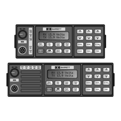
Barrett
Barrett 900 Series User manual
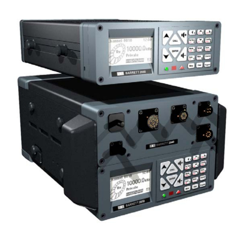
Barrett
Barrett 2000 Series User manual
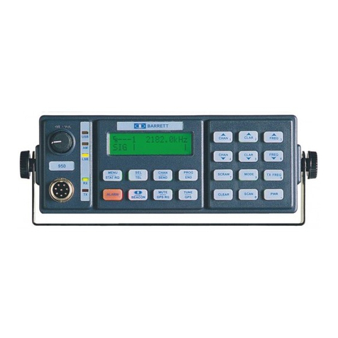
Barrett
Barrett 950 HF SSB Specification sheet
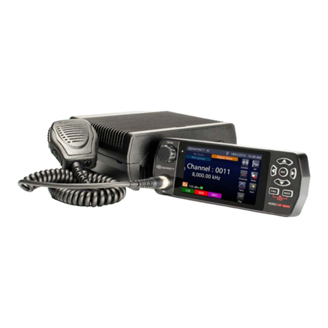
Barrett
Barrett 4050 HF SDR Specification sheet

Barrett
Barrett 4050 HF SDR User manual
Barrett
Barrett 2030 Specification sheet

