Barrett 4015 User manual
BCM401500/01
© Barrett Communications
Head Ofce:
Barrett Communications Pty Ltd
47 Discovery Drive, Bibra Lake, WA 6163 Australia
Tel: +61 8 9434 1700 Fax: +61 8 9418 6757
Email: [email protected]
www.barrettcomms.com
4015 Marine Automatic
Antenna Tuner
Operating Manual
4 015

2
Contents
Introduction .............................................................................................................. 3
Installation................................................................................................................ 4
Antenna Selection ............................................................................................................. 4
Antenna ............................................................................................................................. 5
Transceiver and Tuner Mounting....................................................................................... 7
Ground (Earth) System ..................................................................................................... 8
Corrosion ........................................................................................................................... 9
Electrical Checkout ............................................................................................................ 9
Connection Details For a 4050 Transceiver and 4015 Automatic Antenna Tuner
in a Marine Installation .......................................................................................... 10
Setting the Tuner in a 4050 .................................................................................... 12
Connector................................................................................................................ 13
Control Connector............................................................................................................13
Warranty Statement ............................................................................................... 14

3
4015 MARINE AUTOMATIC ANTENNA TUNER
Introduction
Antennas such as long-wires, vertical whips and loop congurations require an
Antenna Tuning Unit to operate correctly.
Housed in a fully weatherproof enclosure, the 4015 Marine Antenna Tuning Unit
(P/N BC401500) (ATU) will tune long wire antennas effectively from 2.5 to 10
metres and wire loop antennas or whip antennas over a frequency range of 2
to 30 MHz. Tuning is rapid, typically less than one second the rst time RF is
applied, either whilst the operator is talking or when the “Tune” control is acti-
vated on the transceiver.
The 4015 ATU features a memory facility that stores the conguration required
to tune to a frequency. On any subsequent use of that frequency, the 4015
recongures to the stored settings in, typically, less than 130 milliseconds. Fol-
lowing initial tuning, the antenna’s VSWR is monitored. If any signicant varia-
tion occurs, the 4015 will re-tune the antenna automatically.

4
4015 MARINE AUTOMATIC ANTENNA TUNER
Installation
The Barrett 4015 automatic antenna tuner is designed for use in land base sta-
tion and maritime HF services. Primarily designed for operation with end-fed
unbalanced antennas such as whips and long wires, the tuner is built in a water-
proof impact resistant, moulded ABS plastic enclosure.
Antenna Selection
The 4015 automatic antenna tuner will operate into almost any end-fed antenna
with a length exceeding 2.5 metres, providing an effective ground (earth) is
used.
The antenna efciency will be proportional to the length of the antenna and
will be maximum when the length of the antenna approaches ¼ wavelength.
It is advisable to limit the wire antenna to ¼ or ¾ wavelength at the highest
frequency to be used.
Please contact Barrett Communications with your vessel’s specications for addi-
tional assistance.
5
4015 MARINE AUTOMATIC ANTENNA TUNER
Antenna
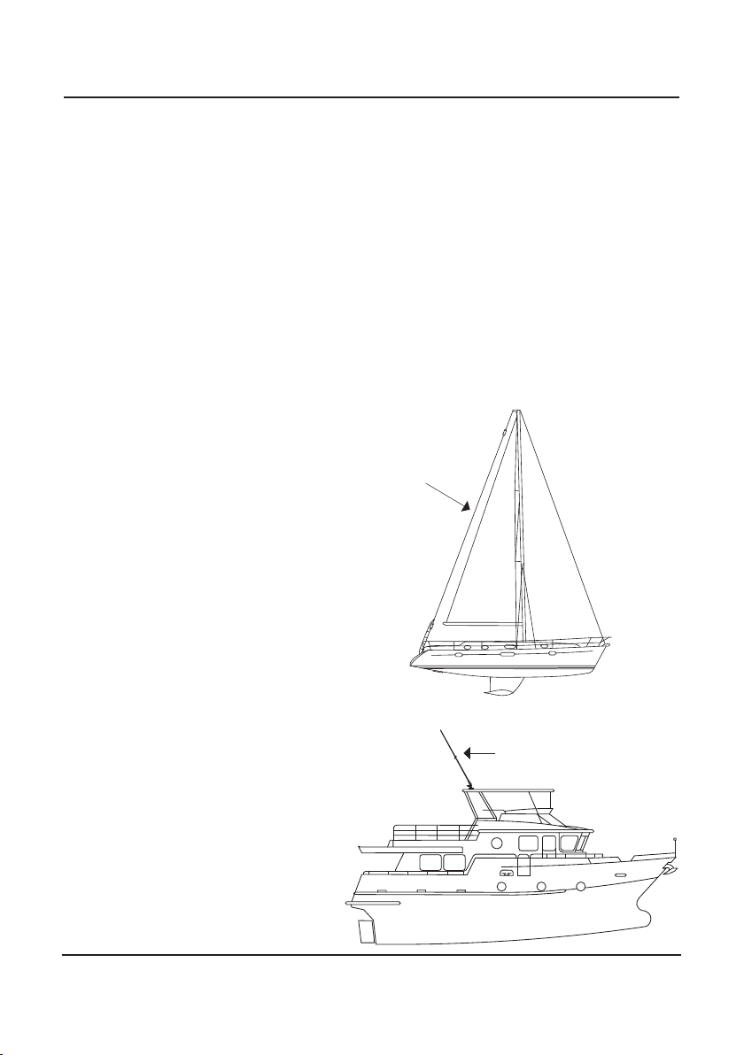
On sailing vessels the antenna can either be an insulated backstay or a whip
antenna mounted vertically, usually on the stern. Best performance will be
achieved by using an insulated backstay as the radiating length will be longer
than that available when using a whip.
NOTES:
• The top insulator on the backstay should be approximately 300 mm from
the mast and the bottom insulator should be at eye level above the deck.
• The distance between insulators should be greater than 10 metres and less
than 35 metres.
• A whip antenna is generally used on small to medium sized power vessels.
There are different length whips to suit the vessel length.
Yacht: Backstay operates
as a long-wire antenna
Large Power Boat:
Whip Antenna
Backstay

6
4015 MARINE AUTOMATIC ANTENNA TUNER
Horizontal Element
Vertical Element
Antenna Tuner
Descriptions
Ship:
There are many possible
antenna congurations for a
ship and tuner. The below illus-
trations are guides only.
Please contact Barrett Communications with your vessel’s specications for addi-
tional assistance.
Tuner positions
Good - High position Better - Mid position Best - Low position
Antenna wire positions
Good - Vertical Better - Inverted L Best - Two-wire
inverted L

7
4015 MARINE AUTOMATIC ANTENNA TUNER
Transceiver and Tuner Mounting
1. Select a suitable position in the vessel to mount the transceiver. It should be
a position that is out of the weather and easily accessible to the operator,
whilst as close as practical to the 13.8 V DC power source.
2. Mount the transceiver to a solid xing point using the mounting cradle.
Make sure there is sufcient space at the rear of the transceiver to connect
the power and antenna cables.
NOTES:
• The antenna tuner should be mounted as close to the antenna feed point as
possible. In metal vessels the length of the feeder from the antenna tuner
to the feed-through insulator, inside the vessel, should be kept less than 1
metre.
• The antenna feed cable should be a suitable high voltage cable. Care should
be taken to avoid sharp points when terminating the cable to prevent
corona discharges.
• The interconnect cable supplied with the antenna tuner should be routed
away from other cables back to the transceiver and connected as indicated
on page 10.

8
4015 MARINE AUTOMATIC ANTENNA TUNER
Ground (Earth) System
The ground (earth) system is a key part of the overall antenna system and con-
sequently the system operation. An inadequate ground (earth) system is the
primary cause of poor performance and tuning problems. There is little point in
installing the antenna unless a good ground (earth) system or counterpoise can
be provided.
Whichever method is used, the ground (earth) run from the ground (earth) plate
to the antenna tuner should be as short as possible and use copper strap at least
50 mm wide (wider if available).
Metal Hulled Vessels
Metal hulled vessels provide an almost perfect ground (earth). The tuner ground
(earth) terminal should be connected directly to the hull using the shortest possi-
ble ground (earth) strap. The point of connection to the hull should be prepared
so that it is free of paint and rust to ensure a good contact area with minimum
electrical resistance.
Wooden or Fibreglass Vessels
Wooden or breglass vessels present more of a problem to ground (counter-
poise). Ideally the vessel should be tted with an external copper ground (earth)
sheet, connected to the interior of the vessel by suitable stud or an ground
(earth) plate (“E” plate Barrett P/N BCA91700)
Should neither of these methods be available, acceptable ground points include
stainless steel stanchion, through mast, through hull or a metal water tank.
NOTES:
• Do NOT connect the ground terminal to anything combustible i.e a gas or
electrical pipe, fuel tank, engine or oil catch pan
• Ground cables should not be connected to more than one ground point.
• Consideration must always be given to the problem of electrolysis. Severe
structural damage may occur if electrolysis is present. Consult your maritime
experts for more information concerning electrolysis.

9
4015 MARINE AUTOMATIC ANTENNA TUNER
Corrosion
All connections in marine situations are subject to corrosion and oxidation. To
minimise this all joints should be cleaned and have silicon grease applied before
assembly. Under severe conditions joints should be protected with self vulcanis-
ing rubber tape.
Electrical Checkout
1. After mechanical installation is complete, select the highest frequency to
be used on the transceiver. A directional watt-meter may be inserted in the
coaxial transmission line between the transceiver and the tuner, if desired,
although the internal tuner of the 4050 transceiver is accurate.
2. The tune mode on the transceiver is then activated. Upon application of RF
energy, the tuner should start to tune, indicated by the ‘clattering’ of the
tuner relays. After a few seconds the relay noise will cease. The transceiver
should indicate “Tune OK” and the watt-meter reected power should indi-
cate a low value consistent with a VSWR of better than 2:1.
3. Select the lowest desired frequency on the transceiver and repeat the above
procedure.
The result should be the same, except that the tune cycle may take longer. If the
above procedure does not give the results as indicated, check that the antenna
length and connections are correct and re-check all ground (earth) connections.
NOTE:
• When received, the Barrett 4015 automatic antenna tuner memory system
will usually not have any pre-stored tuning information appropriate to
your installation. To allow the 4015 to ‘learn’ its tuning information simply
proceed from one channel to the next allowing the normal tune cycle to
take place. Each successful tune is ‘memorised’ so that when that channel
is re-selected, the tuner will almost instantaneously retune to that fre-
quency.
10
4015 MARINE AUTOMATIC ANTENNA TUNER
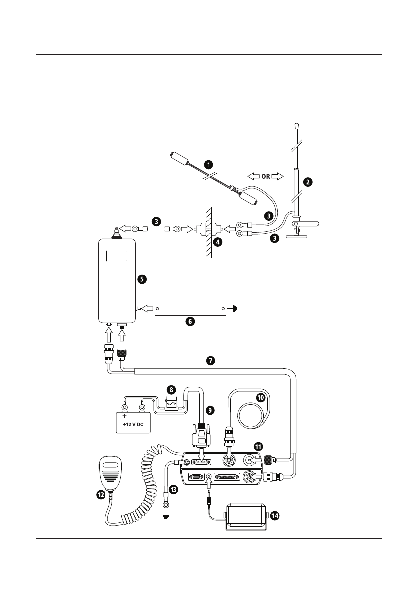
Connection Details For a 4050 Transceiver and
4015 Automatic Antenna Tuner in a Marine Instal-
lation

11
4015 MARINE AUTOMATIC ANTENNA TUNER
1
Sailing vessel back stay antenna or longwire antenna
2
Marine Whip Antenna
3
Tinned high voltage antenna feeder cable. Rated to withstand the
voltages of up to 10000V that can occur in HF transmission. Flexible
56/0.30 stranding.
4Feed Through Insulator (P/N BCA91701)
5Barrett 4015 Marine Automatic Antenna Tuner (P/N BC401500)
6Copper Earth Strap 50 mm (w) x 0.5 mm (d) x appropriate length
7Control cable 6 m - integral coaxial/control with connectors to suit
4000 series (P/N 4019-00-02)
8
Fuse, in-line, with spare
9
DC Power Cable
10
External GPS Receiver option (P/N BCA40009)
11
Barrett 4050 HF SDR Transceiver(rear) (P/N BC405000)
12
Microphone (P/N BCA40010)
13 Ground (earth)
14 Extension speaker supplied with transceiver (P/N BCA40015)

12
4015 MARINE AUTOMATIC ANTENNA TUNER
Setting the Tuner in a 4050
From the Settings menu of a Barrett
4050 HF SDR Transceiver, select I/O
followed by Antenna 1 type (if using
in the antenna 1 position.
Select 4011/4015 Auto Tuner.
NOTE:
Earlier versions may not show
4011/4015 Auto tuner and should,
instead, select 4011 Auto Tuner.
Settings I/O
13
4015 MARINE AUTOMATIC ANTENNA TUNER
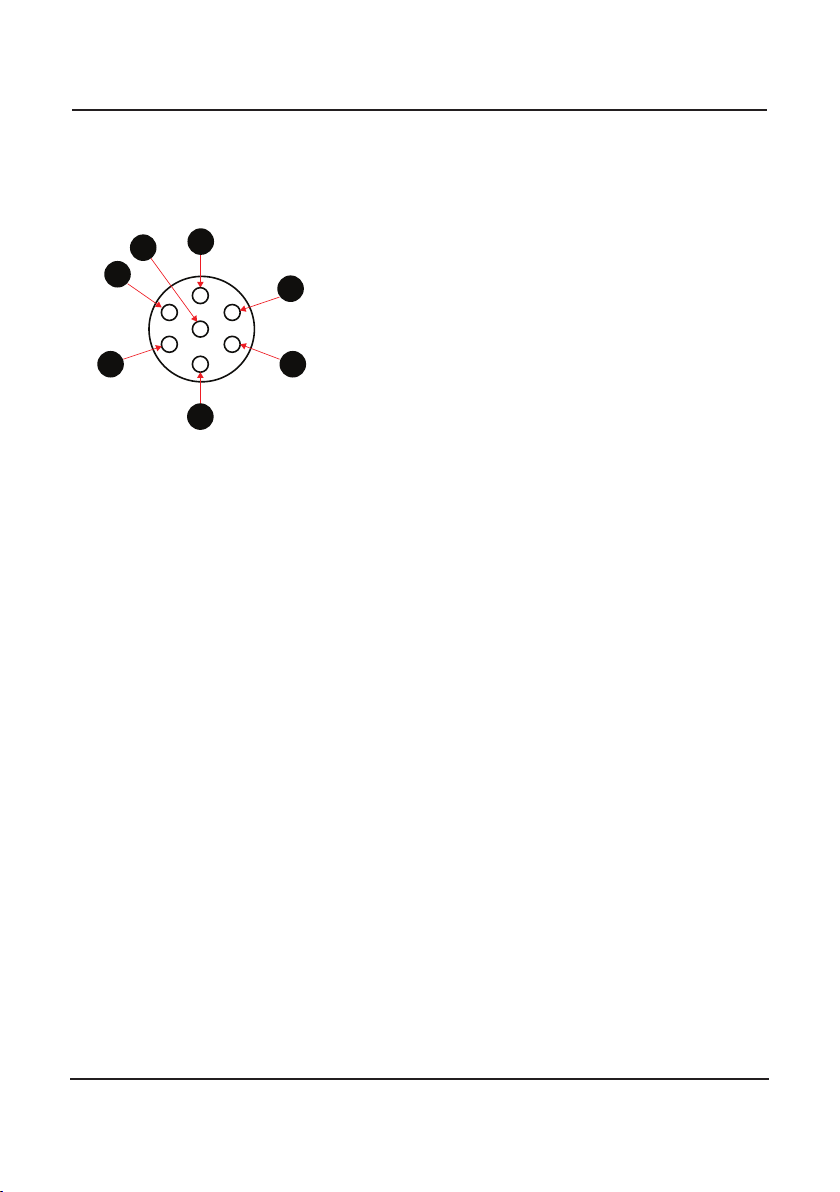
Control Connector
Signal Level
A. GND and shield
B. Unused
C. Unused
D. Scan
E. Tuned
F. ATU V+
G. Unused
Ground and cable shield
Unused
Unused
ATU Scan line
ATU Tuned signal
ATU Voltage 13V8
Unused
A
C
E
F
G
B
D
Connector

14
4015 MARINE AUTOMATIC ANTENNA TUNER
Warranty Statement
Barrett Communications (hereafter referred to as ‘Seller’) provides a three
(3) year warranty on all Barrett products from the date of shipment from the
Seller. A one (1) year warranty from the date of shipment from the Seller is
provided for all batteries.
Each warranty guarantees acceptable performance of the product under
normal recommended conditions for the duration of the warranty period. In
cases of accident, abuse, incorrect installation or maintenance by a non-Seller
representative, subjection to abnormal environmental conditions, negligence
or use other than those in accordance with instructions issued by the Seller, the
warranty shall be voided. In addition, this warranty shall not cover low perfor-
mance – specically the distance or quality of transmission and reception - due
to unfavourable environmental or locational conditions. Nor shall this warranty
cover the quality of transmission and reception of transceivers mounted in
vehicles or vessels that have not been sufciently electrically suppressed.
Should any fault due to bad design, workmanship or materials be proven at
any time within the warranty period, the Seller will rectify such fault free of
charge provided that the equipment is returned, freight paid, to Barrett Com-
munications Pty Ltd head ofce or to an authorised service centre. The repaired
or replaced product will remain covered under and throughout the term of
the original warranty period up to its expiration. No repair or replacement will
extend the warranty term past the original thirty-six (36) month anniversary of
the original date of shipment from the Seller.
Firmware and software (pre-installed, stand-alone or provided as an update),
hereafter referred to as ‘Software’, is guaranteed to perform acceptably within
the specications provided by the Seller, provided that the Software is within
the warranty period.
Should Software not perform acceptably, the Seller will use all commercially
reasonable efforts to correct such nonconformity as reported to the Seller
directly or via a support representative. The Seller is not obliged to update Soft-
ware under warranty if the nonconformity is caused by a) the use or operation
of the Software in an environment other than intended or recommended by
the Seller in relevant documentation, or b) modications made to the Software
not authorised or undertaken by the Seller or a representative of said Seller.
Subject to the matters set out in this warranty, no liability, expressed or implied
is accepted for any consequential loss, damage or injury arising as a result of a
fault in the equipment and, all expressed or implied warranties as to quality or
tness for any purpose are hereby excluded.
This warranty does not extend to products supplied by the Seller which are not
designed or manufactured by it. The Seller will however make every endeavour

15
4015 MARINE AUTOMATIC ANTENNA TUNER
to ensure that the purchaser receives full benet on any warranty given by the
original equipment manufacturer.
This warranty is restricted to the original purchaser except where the original
purchaser is a reseller authorised by the Seller who has purchased for the pur-
pose of resale, warranty shall be extended to the reseller’s customer.
Contact Details
Our customer / dealer technical support department can be contacted via land
mail, email, telephone or via support ticket on the technical support web page.
https://www.barrettcommunications.com.au/support/
Barrett Communications Pty Ltd Head Ofce:
PO Box 1214, Bibra Lake WA 6965 AUSTRALIA
Toll Free Tel: 1800 999 580 (Within Australia)
Tel: +618 9434 1700
Fax: +618 9418 6757
email: [email protected]
Telephone support from the Australian ofce is available from 7:30 am to 4:00
pm local time Monday to Friday.
Barrett Communications – Europe:
Unit 9, Fulcrum 2 Victory Park, Solent Way,
Whiteley Hampshire PO15 7FN United Kingdom
Tel: +44 (0) 1489 880 332
Fax: +44 (0) 1489 565 422
email: [email protected]
Telephone support from the UK ofce is available from 8:30 am to 5:00 pm
local time Monday to Friday.
Barrett Communications Corporation USA:
90 Ofce Parkway
Pittsford, N.Y. 14534
United States of America
Tel: +1 585 582 6134
email: [email protected]
Telephone support from the USA support ofce is available from 8:30 am to
5:00 pm local time Monday to Friday.

Head Ofce:
Barrett Communications Pty Ltd
47 Discovery Drive, Bibra Lake, WA 6163, Australia
Tel: +61 8 9434 1700 Fax: +61 8 9418 6757
Europe:
Barrett Communications - Europe
Unit 9, Fulcrum 2, Solent Way, Whiteley, Hampshire, PO15 7FN, United Kingdom
Tel: +44 (0) 1489 880 332 Fax: +44 (0) 1489 565 422
Email: [email protected]
USA:
Barrett Communications USA Corp.
90 Ofce Parkway, Pittsford, NY 14534, United States of America
Tel: +1 585 582 6134
Email: [email protected]
www.barrettcomms.com
Table of contents
Other Barrett Tuner manuals


