axing MK 8-00 User manual

MK 8-00 | MK 16-00
MK 8-06 | MK 16-06
Multituner | DVB-C/DVB-T compact headend
Operation instructions

Operation instructions | MK 8-00 | MK 16-00 | MK 8-06 | MK 16-06
22018-10-05 | Technical improvements, changes in design, printing- and other errors expected.
Table of contents
1. Product description.........................................................................................................................................................4
1.1. General..................................................................................................................................................................4
1.2. Scope of delivery ...................................................................................................................................................4
1.3. Inputs/multituner...................................................................................................................................................5
1.4. Output/modulators ................................................................................................................................................6
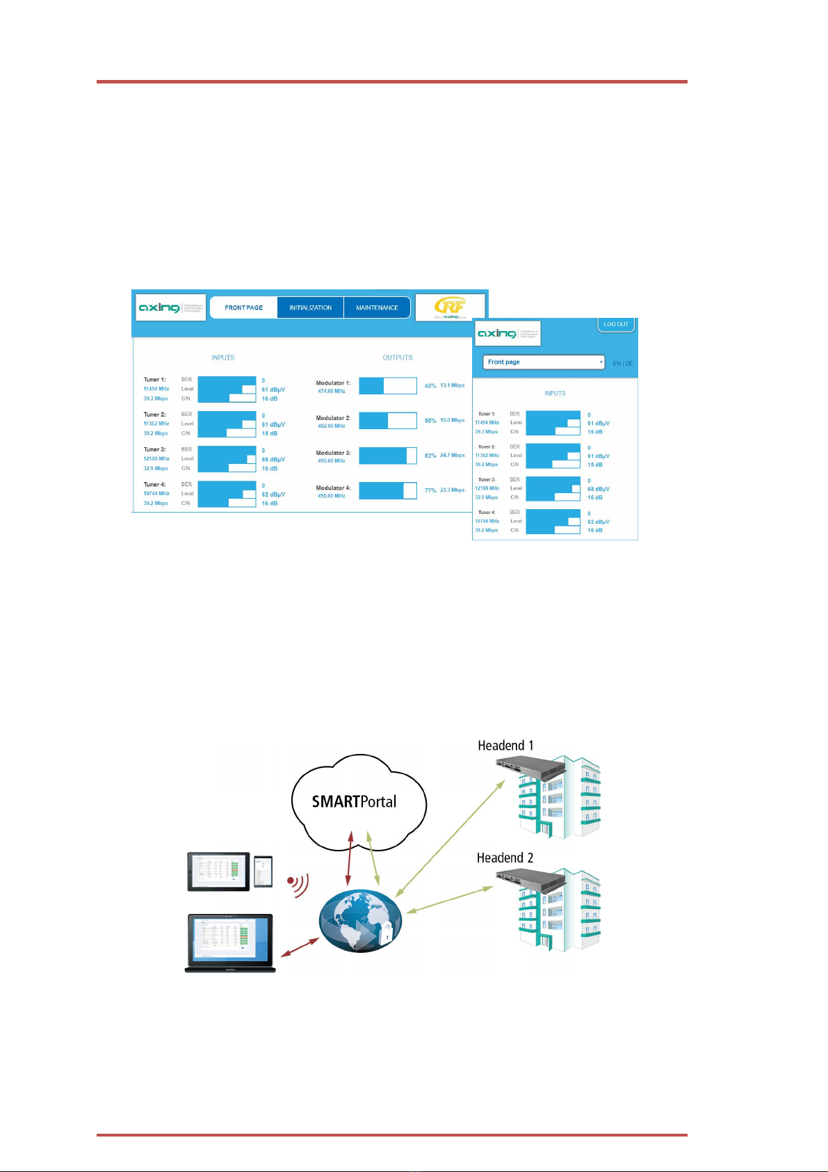
1.5. Graphical user interface.........................................................................................................................................6
1.6. SMARTPortal .........................................................................................................................................................6
1.7. Display elements and connectors ..........................................................................................................................7
1.7.1. MK 8/16-0x...................................................................................................................................................7
1.7.2. MK 8-06/16-06.............................................................................................................................................7
2. Mounting and Installation...............................................................................................................................................8
2.1. Wall mounting.......................................................................................................................................................8
2.2. Mounting in a 19“ rack .........................................................................................................................................9
2.3. Equipotential bonding ...........................................................................................................................................9
2.4. Power supply.........................................................................................................................................................9
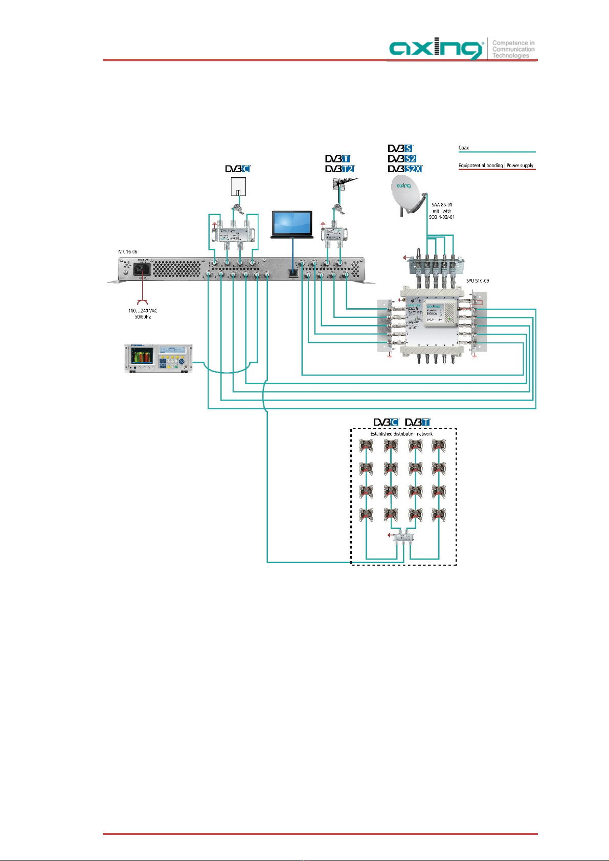
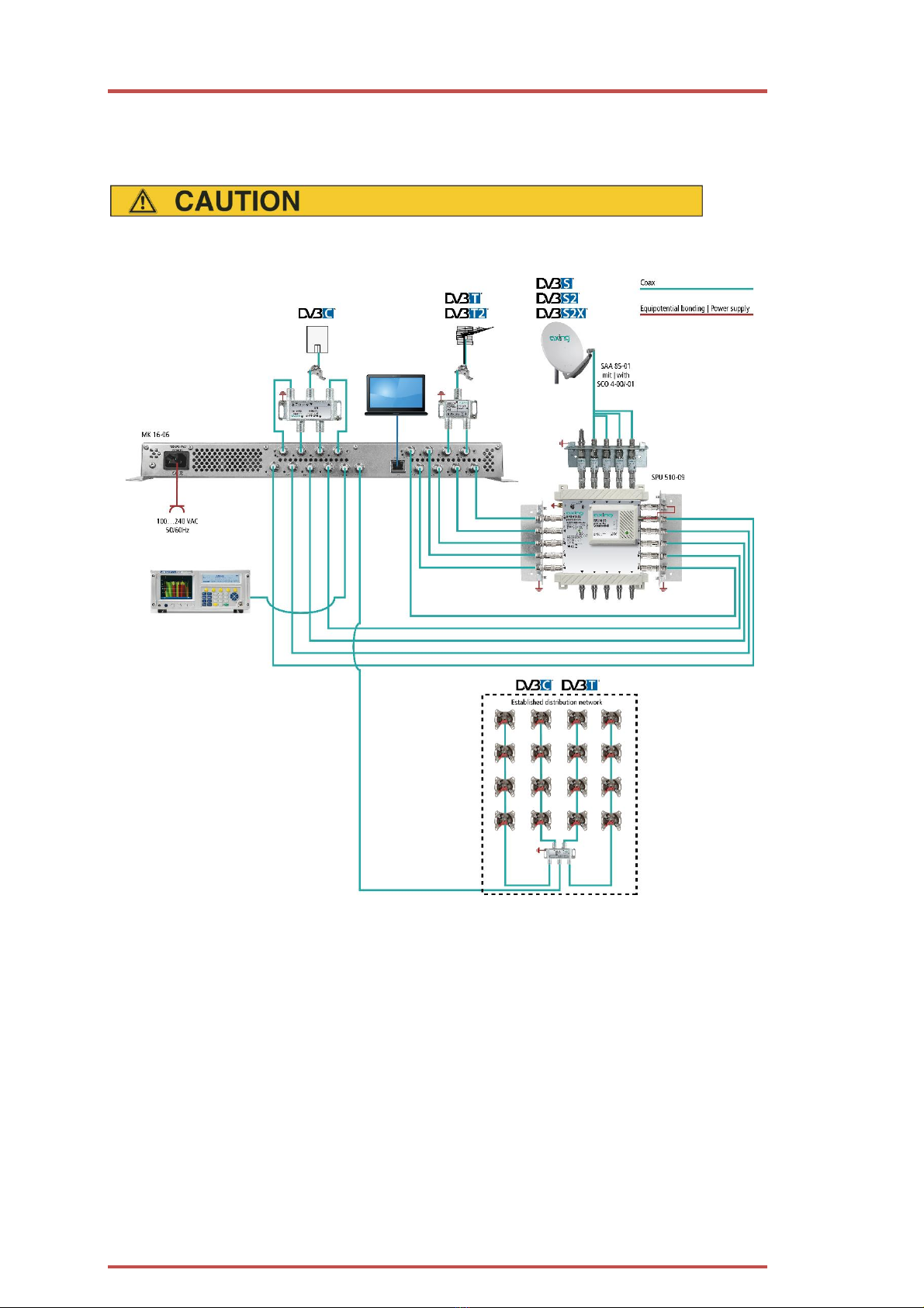
2.5. RF Installation......................................................................................................................................................10
2.5.1. Connection to DVB-T/T2 or DVB-C..............................................................................................................10
2.5.2. Connection to DVB-S/S2/S2x ......................................................................................................................10
2.5.3. Output........................................................................................................................................................10
2.6. Connection to the Internet...................................................................................................................................11
3. Configuration................................................................................................................................................................13
3.1. Login and logout .................................................................................................................................................14
3.2. Front page ...........................................................................................................................................................15
3.2.1. Input...........................................................................................................................................................15
3.2.2. Outputs ......................................................................................................................................................15
3.3. Initialization phase 1 ...........................................................................................................................................16
3.3.1. DVB-S/S2/S2x .............................................................................................................................................16
3.3.2. DVB-C, DVB-T or DVB-T2............................................................................................................................17
3.3.3. Bit error rate...............................................................................................................................................18
3.3.4. Found programmes ....................................................................................................................................18
3.4. Initialization phase 2 ...........................................................................................................................................18
3.4.1. Remux mode ..............................................................................................................................................19
3.4.2. Cross Multiplex Mode ................................................................................................................................20
3.4.3. Select all programs.....................................................................................................................................22
3.4.4. LCN (Logical Channel Numbering)..............................................................................................................23
3.4.5. PID Filtering (with MKS 1-01).....................................................................................................................24
3.5. Initialization phase 3 – DVB-C.............................................................................................................................25
3.5.1. Configuration of the modulator..................................................................................................................25
3.5.2. Fill level ......................................................................................................................................................26
3.5.3. Selected Programmes.................................................................................................................................26
3.6. Initialization phase 3 – DVB-T .............................................................................................................................27
3.6.1. Configuration of the modulator..................................................................................................................27
3.6.2. Fill level ......................................................................................................................................................28
3.6.3. Selected Programmes.................................................................................................................................29
3.7. Maintenance........................................................................................................................................................30
3.7.1. Updating software......................................................................................................................................30
3.7.2. Modulation standard..................................................................................................................................31
3.7.3. Changing the IP address.............................................................................................................................32
3.7.4. Changing the password..............................................................................................................................33
3.7.5. Rebooting...................................................................................................................................................34
3.7.6. Erasing service data....................................................................................................................................34
3.7.7. Save Initialization Data...............................................................................................................................34
3.7.8. Upload Initialization Data...........................................................................................................................35
3.7.9. Device name...............................................................................................................................................35
3.7.10. Access to SMARTPortal ..............................................................................................................................36
3.7.11. Log files......................................................................................................................................................36
3.7.12. Channel list for all devices..........................................................................................................................37
3.7.13. Network Information Table (NIT)................................................................................................................37
4. Use of CA modules........................................................................................................................................................42
4.1. Insertion of CA modules ......................................................................................................................................42
4.2. CI menu for SKM 4x-04M ....................................................................................................................................42
4.2.1. Using CI menu............................................................................................................................................42
4.3. Decryption of programmes..................................................................................................................................43
5. Technical specifications.................................................................................................................................................44

2018-10-05 | Technical improvements, changes in design, printing- and other errors expected. 3
Safety instructions:
∂The installation of the device and repair work on the device must be carried out only by a professional
in accordance with the applicable VDE directives. In case of incorrect installation, no liability is
assumed.
∂Never open the device. There are no parts to be maintained by the user inside the device, however,
lethal voltages are present. This also applies to cleaning the device or working on the connections.
∂Use only the mains cable enclosed to the device. Never replace any parts or make any modifications
to the mains cable. Otherwise, there is a risk of death.
∂If you intend not to use the device for a longer period of time, we recommend you to completely
disconnect the device from the mains for safety reasons and for saving energy by pulling out the
mains plug.
∂Let the device adjust to the room temperature before commissioning, in particular if condensation is
present on the device, or if it was exposed to large temperature fluctuations.
∂The device must be operated only in moderate climate.
∂The device must be operated only in dry rooms. In damp rooms or outdoors, there is a risk of short-
circuits (attention: risk of fire) or electrical shocks (attention: risk of death).
∂The device shall not be exposed to dripping or splashing. Do not place objects filled with liquids such
as vases on the device.
∂Plan the mounting or installation location such that you can easily reach the mains plug and interrupt
the electric circuit in dangerous situations. Select the mounting or installation location such that
children cannot play near the device and its connections without supervision. The mounting or
installation location must allow a safe installation of all connected cables. Power supply cables and
supply cables must not be damaged or squeezed by any objects.
∂Operate the device only on a flat, firm surface and protect it against unintentional movements.
∂Never expose the device to direct solar irradiation and avoid direct vicinity of heat sources (e.g.
heaters, other electrical appliances, fireplace, etc.). It must be always ensured that devices with
cooling elements or ventilation slots are not covered or obstructed.
∂Ensure generous air circulation around the device. This will prevent possible damage to device and
risk of fire due to overheating. It must be always ensured that cables are not located near heat
sources (e.g. heaters, other electrical appliances, fireplace, etc.). The unit must be wall mounted with
at least 5 cm clearance along the 4 sides. For 19-inch rack mounting, there must be at least 5 cm
clearance in front of and behind the unit.
∂In particular, the warranty and liability shall be excluded for the consequences of incorrect use, in
case of incorrect modifications or repair work carried out by the customer. Use the device only as
described in the operating instructions and in particular according to the state-of-the-art.
∂The antenna system must be installed and grounded according to the current DIN EN 60728-11
standard.
Herewith AXING AG declares that the marked products comply with the valid guidelines.
You can call up the complete EU declaration of conformity for download by entering the
article in the search field at www.axing.com.
WEEE Nr. DE26869279 | Electrical and electronic components must not be disposed of
as residual waste, it must be disposed of separately.

Operation instructions | MK 8-00 | MK 16-00 | MK 8-06 | MK 16-06
42018-10-05 | Technical improvements, changes in design, printing- and other errors expected.
1. Product description
1.1. General
MK 8-00 Eight independent multituner inputs
Transmodulates 8 × DVB-S/S2/S2x/T/T2/C into 8 × DVB-C or DVB-T (depending on the
configured modulation standard, see 3.7.2 on page 31)
Expandable to 16 modulators with MKS 8-16 software.
MK 8-06 Like MK 8-00, with 6 CI slots (see chapter 4 on page 42)
MK 16-00 16 independent multituner inputs
Transmodulates 16 × DVB-S/S2/S2x/T/T2/C into 16 × DVB-C or DVB- T (depending on the
configured modulation standard, see 3.7.2 on page 31)
MK 16-06 Like MK 16-00, with 6 CI slots (see chapter 4 on page 42)
Common Features:
∂Remux | Crossmultiplex
∂Web-based configuration | Remote maintenance
∂Suitable for AXING SMARTPortal
∂Can be used for wall mounting or as a 19" unit
∂Built-in power supply
1.2. Scope of delivery
1 × Compact headend
1 × AC power cord
1 × Quick start guide

2018-10-05 | Technical improvements, changes in design, printing- and other errors expected. 5
1.3. Inputs/multituner
Headend devices with multituner can receive DVB-S/S2/S2x, DVB-T/T2 or DVB-C. For receiving DVB-T/T2 or
DVB-C the LNB power has to be switched off before connecting a antenna cabel to one of the HF
inputs (see 3.3.2 on page 17)!
Direct connection to the LNBs
The devices have a remote supply voltage for the LNB and DiSEqC 1.0 functionalities at the inputs. The inputs
can be connected directly to the LNB.
Multiswitches as input distributors (recommended)
Optionally, you can also use multiswitches as input distributors. The advantage of this solution is that you can
set both the polarization and the satellite via the user interface. Changes in the list of programmes can be
made using remote maintenance, so that it is not necessary to change or modify the input distribution on site.
Demodulation of the data stream
The selection of the frequency and the demodulation of the data stream are both done in the tuner.
If needed, the programmes from the data flow of the demodulated transponder can be filtered (Remux mode).
Thanks to the Cross Multiplex Mode, FTA programmes (Free to Air) can be filtered from the data flow of
several tuners for a common output channel and be bundled again.
The prepared data flow is passed on to the modulators.

Operation instructions | MK 8-00 | MK 16-00 | MK 8-06 | MK 16-06
62018-10-05 | Technical improvements, changes in design, printing- and other errors expected.
1.4. Output/modulators
The MK 8-0x have eight output modulators. The MK 16-0x have 16 output modulators. All modulators can be
set to any output channel (DVB-C = S2…K87 | DVB-T = S2…K69).
1.5. Graphical user interface
The settings can be changed via the user interface of the integrated web interface. To access the user interface
and thus configure the devices, you need a standard PC/laptop with a network interface and the actual version
of the installed web browser (left).
The configuration interface is "mobile ready" and can therefore also be used from the smartphone or tablet
(right).
1.6. SMARTPortal
AXING ensures with its SMARTPortal, a web-based cloud application, an easy remote access on web
configuration surfaces of its headends.
With AXING’s SMARTPortal a worldwide configuration of all settings or software updates can be ensured. On
customer request AXING can provide the necessary support.
AXING headends ensure a continuous secure and encoded connection to the AXING SMARTPortal. Only
requirement on site is an internet connection (e. g. via LAN, EoC, EoC-WLAN-Bridge, 3G/LTE-Router). There is
no complicated configuration of a router and no additional software for the local computer needed (see 2.6 on
page 11).

2018-10-05 | Technical improvements, changes in design, printing- and other errors expected. 7
1.7. Display elements and connectors
1.7.1. MK 8/16-0x
1. LED indicators
Green = modulation is ok
Green (blinking) = something is missing from the programmed TS
Red = modulator overload.
2. Equipotential bonding connection
3. Mains connection
4. HF input LEDs:
Yellow = MPEG data stream present,
Off = MPEG data stream not present
5. RF input 1…4
6. RF input 5…8
7. RF input 9…12 (MK 16-0x only)
8. RF input 13…16 (MK 16-0x only)
9. Test port
10. RF output
11. RJ45 Ethernet connector
1.7.2. MK 8-06/16-06
MK 8-06 and MK 16-06 each have 6 CI slots (CI1 ... CI6).
Which encrypted program you decrypt with which interface, you determine in the configuration.

Operation instructions | MK 8-00 | MK 16-00 | MK 8-06 | MK 16-06
82018-10-05 | Technical improvements, changes in design, printing- and other errors expected.
2. Mounting and Installation
Installation must be performed by authorized and skilled electricians only.
Before mounting and installation, pull the mains plug (1)!
The antenna system must be installed and grounded according to the EN 60728-11 standard.
The compact headend can be mounted on either at the wall or be mounted in a 19 "rack.
2.1. Wall mounting
The compact headend are factory-fitted with wall brackets.
Note: The unit must be wall mounted with at least 5 cm clearance along the 4 sides.
The installation must be carried out on an even and vertical surface (any unevenness must be
compensated).
Fix the headend with with minimum four pcs. of 4 × 30 mm screws.
The headend must be connected to the equipotential bonding according to EN 60728-11 (3)

2018-10-05 | Technical improvements, changes in design, printing- and other errors expected. 9
2.2. Mounting in a 19“ rack
Note: For 19-inch rack mounting, there must be at least 5 cm clearance in front of and behind the unit.
Remove the wall bracket from the housing of the compact headend.
Mount the front plate MKZ 1-00 onto the MK 8 / 16-00 (1).
Slide the compact headend into the 19 "rack.
Screw the compact headend with four screws (2).
Maintain the EN 60728-11.
2.3. Equipotential bonding
To connect the outer conductor of the coaxial cable to the equipotential bonding, use e.g. QEW earthing
angles or CFA earth connection blocks at the inputs and output (see 2.5 on page 10).
2.4. Power supply
The 19 "units have a built-in power supply. For example, connect the units to an electrical outlet (100 ... 240
VAC / 50 ... 60 Hz).

Operation instructions | MK 8-00 | MK 16-00 | MK 8-06 | MK 16-06
10 2018-10-05 | Technical improvements, changes in design, printing- and other errors expected.
2.5. RF Installation
2.5.1. Connection to DVB-T/T2 or DVB-C
Before connecting the antenna cabel, the LNB power has to be switched off (see 3.3.2 on page 17).
Active DVB-T antennas have to be supplied by an external power supply.
2.5.2. Connection to DVB-S/S2/S2x
Connection to the LNBs
On the SAT-IF input the compact headends have a remote supply voltage for the LNB and use DiSEqC 1.0
functionalities. Therefore, they can be connected directly to the LNB.
Multiswitches as input distributors
Optionally, you can also use multiswitches as input distributors. The advantage of this solution is that you can
set both the SAT IF level and the satellite via the user interface. Changes in the list of programmmes can be
made using remote maintenance, so that it is not necessary to change or modify the input distribution on site.
2.5.3. Output
If you use more then one compact headend, you have to use a combiner to combine the output signals. Note:
There has to be used galvanic isolator between the output connector and antenna network in Sweden and
Norway state area.

2018-10-05 | Technical improvements, changes in design, printing- and other errors expected. 11
2.6. Connection to the Internet
Connection via Ethernet switch to a router which is connected to the Internet.
Connection via Ethernet over Coax to a router which is connected to the Internet.

Operation instructions | MK 8-00 | MK 16-00 | MK 8-06 | MK 16-06
12 2018-10-05 | Technical improvements, changes in design, printing- and other errors expected.
Connection via EoC 2-01 in „Bridge Client Mode“ to a WLAN router.

2018-10-05 | Technical improvements, changes in design, printing- and other errors expected. 13
3. Configuration
The device is configured via the graphical user interface of the integrated web interface.
To access the user interface, you need a standard PC/laptop with a network interface and the actual version of
the installed web browser. To connect the network interface of the headend to the computer, you need a
commercially available network cable.
The HTTP protocol is used for communication allowing a worldwide remote maintenance of the systems at
various locations via the Internet. Access protection is implemented by means of the password prompt.
IP address:
192.168.0.145
Subnet mask:
255.255.255.0.
The computer and the headend must be in the same subnetwork. The network part of the IP address of the
computer must be set to 192.168.0. and the subnet mask must be set to 255.255.255.0.
The host part of the network address is required for the identification of the devices and can be assigned in the
subnetwork only once. You can allocate to the computer any not allocated host address between 0 and 255.
Hint:
Change the IP address and the subnet mask of your computer accordingly.
(e.g.: IP address:192.168.0.11 and subnet mask: 255.255.255.0)
Control panel > Network connections > LAN connection >Properties > Internet protocol version 4 TCP/IPv4 >
Properties > Use the following IP address:
Click OK to save.
Start your web browser and enter the IP address of the headend: e.g.: 192.168.0.145.

Operation instructions | MK 8-00 | MK 16-00 | MK 8-06 | MK 16-06
14 2018-10-05 | Technical improvements, changes in design, printing- and other errors expected.
3.1. Login and logout
The web-based user interface is protected against unauthorized access. When accessing the user interface, the
first thing is the password request.
Enter the default password: Ramsen8262
Click ENTER PASSWORD.
If you are not automatically forwarded to the start
page, click OPEN PAGE.
The standard language of the user interface is English. In the header, the the language of the user interface can
be changed. The possibilities are German (DE) and English (EN). The chosen language applies until the end of
the session.
To log out, click LOG OUT.
Notes:
∂If the browser is closed while you are still logged in, an automatic logout occurs 2.5 minutes later.
∂If the browser window stays open, there is no automatic logout. It allows monitoring the installation via
the web browser.
Changing the password:
Please change the password immediately after the first commissioning and choose a sufficiently safe
password. Keep this password at a safe place.
Menu item: MAINTENANCE > SET NEW PASSWORD (see 3.7.4 on page 33).
Changing the IP address:
If needed, the headends can be integrated in a network. For this application, some changes must be applied to
the network configuration.
Menu item MAINTENANCE > SYSTEM.
Language

2018-10-05 | Technical improvements, changes in design, printing- and other errors expected. 15
3.2. Front page
The relevant information required for the function of the system are shown on the front page. The decisive
thing is the quality of the signals at the INPUT and the utilization of the modulators at the OUTPUT.
3.2.1. Input
The bit error rate BER of all tuners is shown on the left side. The amount of bit errors for the last 1,000,000
transferred bits is calculated.
Also the LEVEL and the C/N ratio are shown.
3.2.2. Outputs
The fill level of all modulators is shown. 100% modulator fill level correspond to the maximal net data rate of
the output channel.
If the current fill level exceeds the maximal fill level, it may cause image disturbances, e.g. mosaic images.
The data rates of the programmes are not constant. They are dynamically changed by the sender. To ensure an
undisturbed reception, a reserve must absolutely be observed.
We recommend you to set the maximal fill level to 90%.
From a fill level of 95%, this is indicated in red.

Operation instructions | MK 8-00 | MK 16-00 | MK 8-06 | MK 16-06
16 2018-10-05 | Technical improvements, changes in design, printing- and other errors expected.
The number of choosen programmes (see 3.4 on page 18) and the configuration of the modulators (see 3.5 on
page 25) have an influence to the fill level.
3.3. Initialization phase 1
Choose INITIALIZATION from the main menu.
During the first phase of the initialization, the tuner settings required for the scan are made and the station
scanning is carried out. The tuners work independently from each other and after the same principle.
3.3.1. DVB-S/S2/S2x
Click TUNER 1…8 to select one tuner.
Configure the needed settings for all tuners.
The SAT IF frequency of the transponder is entered in the input field Freq (MHz).
The input fields Low LNB LO Freq (MHz) and High LNB LO Freq (MHz) correspond to the oscillator
frequencies of the LNB in low and high band. The default settings of the oscillator frequencies are 9,750 MHz
for the low band and 10,600 MHz for the high band.
In the optional field Polarisation, you can switch from horizontal to vertical.
In the optional field DiSEqC, the DiSEqC command signals can be turned off or set to switch a DiSEqC-enabled
multi switch on the positions 1 to 4.
If required, the operating voltage for the LNB can be switched off via the optional field LNB Power.
After all settings have been made, click SCAN.
A rotating circle is shown during the scanning process.

2018-10-05 | Technical improvements, changes in design, printing- and other errors expected. 17
3.3.2. DVB-C, DVB-T or DVB-T2
Before connecting an antenna cable to an tuner, the LNB Power has to be set to Off
Click TUNER 1…4 to select one tuner.
In the field LNB power choose the option Off.
Enter the center frequency (see table below) for the receiving channel into the field FREQ (MHz).
Channel
Input
Channel
Input
Channel
Input
Channel
Input
S 21
306
21
474
41
634
61
794
S 22
314
22
482
42
642
62
802
S 23
322
23
490
43
650
63
810
S 24
330
24
498
44
658
64
818
S 25
338
25
506
45
666
65
826
S 26
346
26
514
46
674
66
834
S 27
354
27
522
47
682
67
842
S 28
362
28
530
48
690
68
850
S 29
370
29
538
49
698
69
858
S 30
378
30
546
50
706
S 31
386
31
554
51
714
S 32
394
32
562
52
722
S 33
402
33
570
53
730
S 34
410
34
578
54
738
S 35
418
35
586
55
746
S 36
426
36
594
56
754
S 37
434
37
602
57
762
S 38
442
38
610
58
770
S 39
450
39
618
59
778
S 40
458
40
626
60
786
S 41
466
Note: The center frequeny of channels using a bandwith of 7MHz will be rounded down to 3 full digits. For
example: center frequency of CH 5 = 177,5 MHz, the according input = 177.
Note: All other entry fields are not relevant. Modulation and all other important parameter for reception are
detected automatically.
Enter 3- digits for
center frequency Choose “Off”

Operation instructions | MK 8-00 | MK 16-00 | MK 8-06 | MK 16-06
18 2018-10-05 | Technical improvements, changes in design, printing- and other errors expected.
3.3.3. Bit error rate
The BIT ERROR RATE is shown. The amount of bit errors for the last 1,000,000 transferred bits is calculated.
3.3.4. Found programmes
After a successful station scanning, the radio and TV stations are shown in the area FOUND PROGRAMS. The
table contains information about the Program Name, the Type and the Encryption.
3.4. Initialization phase 2
In the initialization PHASE 2, the found programmes are subdivided by tuner.
Click on PHASE 2, to select programs.
After the station scanning in initialization phase 1 no programms are activated.
All lines of the programme table have in the "Modulator" column colored buttons M1 to M8/16. The buttons
correspond to the modulators of the headend. The allocation of the buttons is given in the COLOR CODES
legend.
You can assign programmes to modulators in REMUX MODE or in CROSS MULTIPLEX MODE.
With each programme you asign to an modulator, the data rate rises.
The performed modifications are only taken over by the system when you click on SAVE CHANGES.

2018-10-05 | Technical improvements, changes in design, printing- and other errors expected. 19
3.4.1. Remux mode
If the the Network ID are set on auto, the device works in the Remux mode. In this mode, the IDs from the set
transponder and from the satellite are used and forwarded to the modulators with virtually no changes. The
TS ID1 to TS ID8/16 of the modulators, are also set on auto.
Note:
If the device is already set to CROSS MULTIPLEX MODE, set the Network ID to auto.
Click on SAVE CHANGES.
The device ist set back to REMUX MODE.

Operation instructions | MK 8-00 | MK 16-00 | MK 8-06 | MK 16-06
20 2018-10-05 | Technical improvements, changes in design, printing- and other errors expected.
Assigning programmes
Every tuner is assigned to a modulator. The programmes of the tuner can only be assigned to the associated
modulator.
For example click in table TUNER 1 on M1.
The program is assigned to modulator 1. The button of the modulator is highlighted in color (a new click on
a modulator allow the assignment to be canceled. The modulator fades then again).
Choose the programmes for TUNER 1 to TUNER 8/16.
Click on SAVE CHANGES.
The assignment is saved tot he device.
3.4.2. Cross Multiplex Mode
The cross multiplex mode is used:
∂To split the programmes of a transonder to several modulators.
∂To merge pogams of several transponders into one output channel.
Transmission capacities in the distribution networks can be optimized.
Change the Network ID to a value greater than zero.
Choosen
programs for
modulator 1
Other manuals for MK 8-00
2
This manual suits for next models
3
Other axing Tuner manuals
Popular Tuner manuals by other brands

DaySequerra
DaySequerra M4 Series user manual

Xantech
Xantech AM/FM Radio Tuner owner's manual

Sirius Satellite Radio
Sirius Satellite Radio SiriusConnect SC-C1M installation guide

Denon
Denon TU-280 operating instructions

ELECRAFT
ELECRAFT KAT2 Assembly and operating instructions

Teac
Teac T-R610DAB Service manual