Barrus SHIRE 14 30 User manual

RDG603A8 - Issue 1 - Shire 14 Canal Boat Complete Manual 30, 35, 38, 40, 45, 50.doc
SHIRE CANAL BOAT ENGINE MANUAL
For the following engine models:
SHIRE 14 30
SHIRE 14 35
SHIRE 14 38
SHIRE 14 40
SHIRE 14 45
SHIRE 14 50
Enter your engine identification details in the spaces provided above.
E. P. BARRUS LIMITED, Launton Road, Bicester, Oxfordshire. OX26 4UR
Tel: 01869-363636 Fax: 01869-363610 www.barrus.co.uk

RDG603A8 - Issue 1 - Shire 14 Canal Boat Complete Manual 30, 35, 38, 40, 45, 50.doc
Page 2 of 50
Declaration of Conformity for Recreational Craft Propulsion Engine
with the requirements of Directive 94/25/EC as amended by
2003/44/EC.
Name of Engine Manufacturer: Yanmar Co LTD.
Address: Yanmar Europe B.V, Brugplein 11, 1332 BS Almere-de Vaart, Netherlands.
Name of Authorised Representative: E.P.Barrus LTD
Address: E.P.Barrus LTD, Launton Road, Bicester, Oxon, OX26 4UR, England
Engine type approved according to: Stage II of Directive 97/68/EC, 88/77/EC
Description of Engine(s) and Essential Requirements
Engine Type: Inboard Engine Fuel Type: Diesel Combustion Cycle: 4 Stroke
Identification of Engine(s) covered by this Declaration of Conformity
Engine Model
Engine Type
Engine Family code
Type Approval Certificate Number
Shire 30 / 35
3 TNV 82 A BDSA
G2YDXCL0133MN
e13*97/68DA*2001/63*0558*06
Shire 38 / 40 / 45 / 50
4 TNV 88 DSA
5YDXL2.19K4N
e13*97/68DA*2001/63*0574*06
Shire 70
4 TNV 98 NSA
YD3300DNMGEC
e13*97/68GA*2001/63*0545*11
Essential Requirements
Standards
Other normative
document/method.
Technical
file
Specify in more detail
*= Mandatory standard.
Annex 1.B- Exhaust Emissions
B.1 Engine Identification
B.2 Exhaust emission
requirements
*EN ISO 8178- 1:1996
B.3 Durability
B.4 Owners Manual
Annex 1. C- Noise Emissions
See Declaration of Conformity of the craft in which the engine(s) has(have) been installed
This declaration of conformity is issued under the sole responsibility of the manufacturer. I declare on behalf
of the engine manufacturer that the engine(s) [is (are) in conformity with the type(s) for which above
mentioned EC type-examination or type approval certificate(s) has (have) been issued and]1will meet the
exhaust emission requirements of Directive 94/25/EC as amended by Directive 2003/44/EC when installed in
a recreational craft, in accordance with the engine manufacturer’s supplied instructions and that this (these)
engine(s) must not be put into service until the recreational craft which it is (they are) to be installed has been
declared in conformity with the relevant provisions of the above mentioned Directives.
Tim Hart
Sales Director
Signed: Bicester, UK

RDG603A8 - Issue 1 - Shire 14 Canal Boat Complete Manual 30, 35, 38, 40, 45, 50.doc
Page 3 of 50
PLEASE NOTE:
This manual has been compiled to help you to operate your engine and its associated parts
with safety and pleasure. Please read it carefully and familiarise yourself with the engine
and its parts before operation.
E.P.Barrus reserve the right to change the specification of its products and manuals
without prior notice.
Depending upon the equipment specification of the engine and accessories fitted, there
may be discrepancies with the information presented in this handbook. No claims may be
pursued in this respect.
WARNING:
THIS MANUAL FORMS AN INTEGRAL PART OF THE ENGINE IT ACCOMPANIES, IF
A TRANSFER OF TITLE OCCURS, IT MUST ALWAYS BE HANDED OVER TO THE
NEW OWNER.
WARRANTY
This Limited Warranty provides coverage for five (5) years (or 2000 hours whichever
occurs first) for recreational users and three (3) years (or 2000 hours whichever occurs
first) for commercial users from the date of warranty registration. The repair or replacement
of parts, or the performance of service under this warranty, does not extend the life of this
warranty beyond its original expiry date.
To ensure that you have been registered for your warranty, please ask your Boat-Builder or
Engine supplier to provide your portion of the registration form.
PRM gearboxes are covered by a three (3) year warranty for recreational users and two (2)
years for commercial users.
Engine alternator, starter motor and electrical components are only covered by a one (1)
year warranty.

RDG603A8 - Issue 1 - Shire 14 Canal Boat Complete Manual 30, 35, 38, 40, 45, 50.doc
Page 4 of 50
CONDITIONS THAT MUST BE MET IN ORDER TO OBTAIN WARRANTY COVERAGE
Warranty coverage is only available from an authorised dealer in the country in which the
sale occurred. Routine maintenance outlined in the Owner’s Manual must be performed
using genuine parts in order to maintain warranty coverage. If the customer performs
maintenance, Barrus reserves the right to make future warranty coverage possible only
with proof of proper maintenance.
WARRANTY CLAIMS
Warranty claims shall be made by an authorised dealer or boat builder.
The dealer or boat builder will then arrange for the inspection and any necessary repairs. If
the repairs carried out are not covered by the warranty, purchaser shall pay for all related
labour and material, and any other expenses associated with that service.
WHAT IS NOT COVERED
This limited warranty does not cover routine maintenance items, adjustments, normal wear
and tear, damage caused by abnormal use, operation of the product in a manner
inconsistent with the recommended operation/duty cycle section of the Owners Manual,
accident, submersion, improper installation (proper installation specification and techniques
are set forth in the Operations and First time running sections in this manual), use of an
accessory or part not manufactured or sold by us, or alteration or removal of parts.
Expenses related to crane-out, launch, towing, storage, telephone, rental, inconvenience,
slip fees, insurance coverage, loan payments, loss of time, loss of income, or any other
types of accidental or consequential damages are not covered by this warranty.
Engine electrical systems fitted with alternator boost charge systems or any other electrical
management systems are not covered by warranty.
Engine and fuel equipment is not covered by warranty if bio-diesel is used in the fuel
system. Also if no type of water trap is incorporated into fuel system.

RDG603A8 - Issue 1 - Shire 14 Canal Boat Complete Manual 30, 35, 38, 40, 45, 50.doc
Page 5 of 50
Contents
SECTION 1 - Safety Precautions...................................................................7
1. General................................................................................................................................................. 7
2. Lifting.................................................................................................................................................... 7
3. Rotating Shafts and Belts..................................................................................................................... 7
4. Exhaust System ................................................................................................................................... 7
5. Launching and Lifting Boats................................................................................................................. 7
6. Batteries............................................................................................................................................... 8
SECTION 2 - Engine Identification................................................................9
SECTION 3 - Installation..............................................................................10
1. Ventilation........................................................................................................................................... 10
2. Engine Beds....................................................................................................................................... 10
3. Cooling System.................................................................................................................................. 10
4. Skin Tanks.......................................................................................................................................... 10
5. Engine Cooling Water Inlet and Outlet Hose Connections................................................................ 11
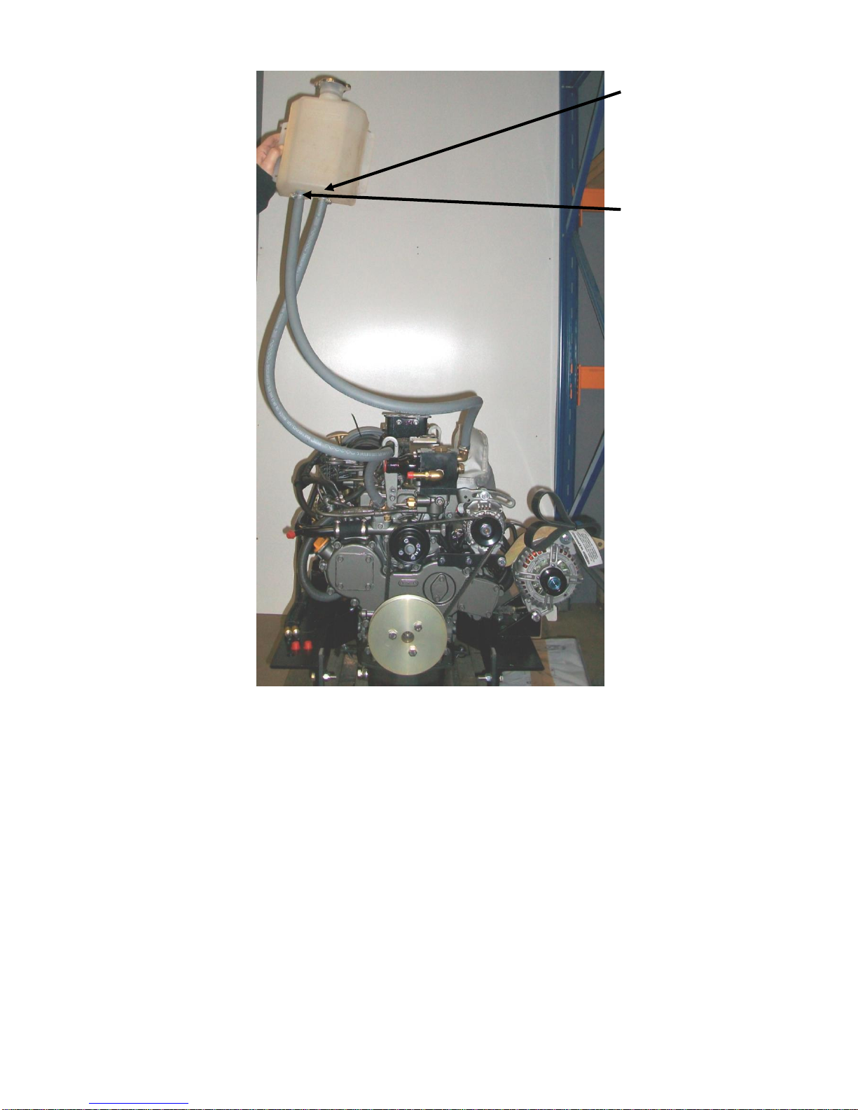
6. Pressurised Water Header Tank........................................................................................................ 11
7. Shaft Connection and Propeller Selection ......................................................................................... 17
8. Engine Anti-Vibration Mounts............................................................................................................. 17
9. Engine Alignment............................................................................................................................... 19
10. Electrics.......................................................................................................................................... 20
11. Electrical Options............................................................................................................................ 20
12. Engine Oil....................................................................................................................................... 21
13. Fuel................................................................................................................................................. 21
14. Coolant ........................................................................................................................................... 22
15. Calorifier ......................................................................................................................................... 22
16. Control Cables................................................................................................................................ 22
17. Domestic Battery Bank................................................................................................................... 23
18. Control Panel.................................................................................................................................. 23
19. Exhaust System.............................................................................................................................. 24
20. Hydraulic Drive Transmissions....................................................................................................... 24
21. Hydraulic Pump Drive Option (Shire 38 / 40 / 45 / 50)................................................................... 25
22. Installation Check list...................................................................................................................... 26
SECTION 4 - Operation................................................................................27
1. Starting the Engine for the First Time ................................................................................................ 27
2. Starting Procedure ............................................................................................................................. 27
3. Stopping Procedure ........................................................................................................................... 28

RDG603A8 - Issue 1 - Shire 14 Canal Boat Complete Manual 30, 35, 38, 40, 45, 50.doc
Page 6 of 50
4. Full Load Running.............................................................................................................................. 28
5. Refuelling ........................................................................................................................................... 28
6. Twin Thermostats –Shire 45 and 50................................................................................................. 28
Diesel Fuel Additive................................................................................................................................... 30
7. Exhaust Back Pressure...................................................................................................................... 30
SECTION 5 - Service Procedure .................................................................30
1. Engine Oil and Filter Change............................................................................................................. 30
2. Air Filter Check & Change.................................................................................................................. 31
3. Gearbox Oil Change .......................................................................................................................... 31
4. Disposal of Oil and Related Items...................................................................................................... 33
5. Primary Fuel Filter Water Drain –Shire 30, 35, 40, 45 & 50.............................................................. 33
6. Primary and Secondary Fuel Filter Change....................................................................................... 34
7. Fuel System Bleeding ........................................................................................................................ 35
8. Cooling System.................................................................................................................................. 35
9. Belt Adjustment.................................................................................................................................. 36
10. Belt Maintenance............................................................................................................................ 36
11. Belt Replacement........................................................................................................................... 36
12. Dash Panel Maintenance ............................................................................................................... 37
SECTION 6 - Service Schedule...................................................................38
Specifications and Capacities ................................................................................................................... 38
Service Intervals........................................................................................................................................ 38
SECTION 7- Wiring Diagrams .....................................................................39
1. Engine Wiring Diagram Shire 30, 35, 38 & 40 ................................................................................... 39
2. Engine Wiring Diagram Shire 30 & 35 (with Glowplugs).................................................................... 40
3. Engine Wiring Diagram Shire 45, 50 & 70 (Shire 40 with optional 240A Alt)..................................... 41
4. Standard Panel Wiring Diagram......................................................................................................... 42
5. Deluxe Panel Wiring Diagram............................................................................................................ 43
6. RDG20710110 - Standard Panel....................................................................................................... 44
7. RDG20710111 –Deluxe Panel.......................................................................................................... 45
SECTION 8 –Dealer List..............................................................................48
SECTION 9 –Shire Service Parts ...............................................................49
Shire Service Record Card..........................................................................50

RDG603A8 - Issue 1 - Shire 14 Canal Boat Complete Manual 30, 35, 38, 40, 45, 50.doc
Page 7 of 50
SECTION 1 - Safety Precautions
1. General
It is the responsibility of the installer/operator to ensure that the finished installation
complies with the relevant health & safety requirements and the recreational craft directive
before commissioning.
Ensure that the engine battery isolator switch is in the off position and the key removed
from the control panel before carrying out any maintenance or repairs.
2. Lifting
The lifting points supplied with the engine are for lifting the engine/gearbox only. A suitable
spreader bar must be employed to prevent over-stressing either bracket during any lift.
3. Rotating Shafts and Belts
The engine and its accessories are not intended to be put into operation until they are
integrated into the boat as a whole. No person should be in the engine compartment and
the engine cover or deck hatches should be closed whilst the engine is running.
4. Exhaust System
Exhaust gases may have temperatures as high as 650oC and contain elements which are
harmful if ingested.
It is therefore essential that exhaust systems are gas tight and lagged to prevent accidental
burning.
5. Launching and Lifting Boats
Care must be taken when launching or craning new boats into or out of the waterway, so
that water does not enter the engine via the exhaust system or air vents. It is
recommended that these are blocked temporarily whilst undertaking this procedure.

RDG603A8 - Issue 1 - Shire 14 Canal Boat Complete Manual 30, 35, 38, 40, 45, 50.doc
Page 8 of 50
6. Batteries
WARNING:
EXPLOSIVE GASSES / SULPHURIC ACID
Batteries can produce explosive gases; keep sparks and flames away from the battery.
NO SMOKING
Batteries contain sulphuric acid; if splashed on skin or eyes, flush well with water and
seek medical advice.
Keep the battery tops and battery compartment ventilated at all times.
If disconnecting the battery; remove the earth lead FIRST; and re-connect it last.
If charging the battery; ensure that the charger is switched off before connecting and
disconnecting.
Do not tip the battery on its side.
Please see label on battery or manufacturers instructions for specific information.

RDG603A8 - Issue 1 - Shire 14 Canal Boat Complete Manual 30, 35, 38, 40, 45, 50.doc
Page 9 of 50
SECTION 2 - Engine Identification
Please quote the engine identification number during any enquiry or when ordering spare
parts. Use the space below to record these details.
This can be found engraved into the brass plate on top of the engine rocker cover and
stamped to the crankcase next to the starter motor.
An example of the engine identification plate is shown below:
Figure 2-1: Engine Identification Badge
Note: There are a number of optional extras that may be fitted to an engine that are not
listed here.
A list of common item service part numbers can be found in Shire service parts in Section
11.

RDG603A8 - Issue 1 - Shire 14 Canal Boat Complete Manual 30, 35, 38, 40, 45, 50.doc
Page 10 of 50
SECTION 3 - Installation
1. Ventilation
All internal combustion engines radiate heat and require cool, clean air to aid complete
combustion.
Please ensure that adequate engine room ventilation is provided, by fitting at least two
vents of an aperture of not less than 10,000 mm2each, (16 in2).
An allowance must be made for any grills, louvres or bends placed in the airflows
and generally an increase of 25% in area is sufficient to overcome any restriction
problems.
2. Engine Beds
These should be a minimum of 10mm thick, extended rearward and be welded to the
hull and forward to the bulkhead. Webs or gussets must be welded in place midway to
prevent flexing.
3. Cooling System
Ensure pipe work to and from the skin tanks is of sufficient bore. Ensure tight bends
and elbows are avoided or kept to a minimum (sizes are listed overleaf).
4. Skin Tanks
The ideal skin tank internal thickness is between 50 and 75mm, the table below will
indicate a suitable tank size. However, volume will not compensate for lack of surface
area. It should be recognised that fitting a large calorifier will increase the theoretical
cooling capacity only until it is up to temperature. It is unlikely that a boat on the inland
waterways will operate at full power for long periods of time. The engine cooling water
outlets are on the right hand (starboard) side of the engine.

RDG603A8 - Issue 1 - Shire 14 Canal Boat Complete Manual 30, 35, 38, 40, 45, 50.doc
Page 11 of 50
Height
Length
Air Bleed Points
Coolant to
Engine
Coolant from
Engine
Figure 3-1: Skin Tank Flow Diagram
Recommended Skin Tank Size
Engine
HP
KW
Skin tank Surface
area m2
Suggested
Height mm
Suggested Length
mm
50
50
37
1.1250
750
1500
45
45
34
1.0
721
1442
38/40
38/40
30/38
1.0
721
1442
30/35
30/35
22/26
0.85
652
1304
Note: Skin tank size must be increased by approx. 10% if a hydraulic drive transmission is
fitted
5. Engine Cooling Water Inlet and Outlet Hose Connections
These are on the right hand (starboard) side of the engine:
Shire 30, 38 28mm OD, Inlet and Outlet
Shire 35, 40 28mm OD, Inlet and Outlet
Shire 45, 50 28mm OD, Inlet and 35mm OD, Outlet
Use a good quality hose that cannot collapse or kink and is capable of working at
temperatures in excess of 100⁰C
6. Pressurised Water Header Tank
The pressurised header tank should be mounted higher than the level of the engine, no
less than 300 mm, and no more than 1 metre from the engine, to prevent cooling
Baffles

RDG603A8 - Issue 1 - Shire 14 Canal Boat Complete Manual 30, 35, 38, 40, 45, 50.doc
Page 12 of 50
system air locks.
Shire 50: a single hose connects the tank to the vertical hosetail fitted into the port side
of the twin thermostat housing.
Shire 30, 35, 38 40 and 45: Two hoses are used on these engines. One is fitted
between the smaller internal diameter (3mm) outlet (on the left hand side of the tank)
and the connection on the port side of the top of the thermostat housing (on 45 the side
of the twin thermostat housing). The second hose is connected between the larger
internal diameter outlet on the (right hand side of the tank) and the ½” hosetail
connection on the engine pipe facing forwards and upwards at 45.
Shire 30 and 35 connections.
A constant rise on pipework is required to prevent air locks.
Figure 3-2: Shire 30/35 Header Tank Connections
Large ID hole
Small ID hole

RDG603A8 - Issue 1 - Shire 14 Canal Boat Complete Manual 30, 35, 38, 40, 45, 50.doc
Page 13 of 50
Figure 3-3: Shire 38 Header Tank Connections
Small ID hole
Large ID hole

RDG603A8 - Issue 1 - Shire 14 Canal Boat Complete Manual 30, 35, 38, 40, 45, 50.doc
Page 14 of 50
Figure 3-4: Shire 40 Header Tank Connections
Large ID hole
Small ID hole

RDG603A8 - Issue 1 - Shire 14 Canal Boat Complete Manual 30, 35, 38, 40, 45, 50.doc
Page 15 of 50
Figure 3-4: Shire 45 Header Tank Connections
Small ID hole
Large ID hole

RDG603A8 - Issue 1 - Shire 14 Canal Boat Complete Manual 30, 35, 38, 40, 45, 50.doc
Page 16 of 50
Shire 50. There is only a single hose connected to the left hand side of the bottle (3mm) outlet.
Figure 3-5: Shire 50 Header Tank Connections
Single
Hole

RDG603A8 - Issue 1 - Shire 14 Canal Boat Complete Manual 30, 35, 38, 40, 45, 50.doc
Page 17 of 50
7. Shaft Connection and Propeller Selection
Some type of flexible coupling must be used to connect the gearbox output flange to the
propeller shaft flange.
Please note, underperforming engines will not be covered under warranty if the cause
of the poor performance is found to be the use of an inappropriate propeller.
8. Engine Anti-Vibration Mounts
Ensure that the engine feet do not end up at the top of the thread on the engine
mounts, this puts undue pressure on them and can result in excessive engine
movement and premature mount failure. If this is a problem put steel packing plates
under the mounts. Packing plates 25mm thick are available: order RDG3906 Engine
mount spacer. Alternatively they can be manufactured locally.
Ensure that the engine has been installed for at least 24 hours before shaft alignment is
checked, to allow the mounts time to settle under the engine weight.
Ensure that the anti-vibration mount centre screw is sufficiently raised so as not to
touch the engine bed. If this occurs, excessive engine vibration will be experienced
through the hull.
For best results, fit the front AV mounts into the front holes in the engine rails. If engine
room space is a problem the mounts can be fitted slightly further back in the alterative
holes, and the front of the rail cut off –leaving 50mm of material to retain strength
(measuring from the centre of the mount hole to the front end of the rail). Note: this
procedure is only possible on non VDO travelpower engines, and may result in a very
slight increase in vibration.
Figure 3-6: Correct Anti-Vibration Mount Installation

RDG603A8 - Issue 1 - Shire 14 Canal Boat Complete Manual 30, 35, 38, 40, 45, 50.doc
Page 18 of 50
Figure 3-7: Correct Anti-Vibration Mount Installation

RDG603A8 - Issue 1 - Shire 14 Canal Boat Complete Manual 30, 35, 38, 40, 45, 50.doc
Page 19 of 50
Figure 3-8: Anti-Vibration Mount Installation Points
9. Engine Alignment
The gearbox output shaft flange and propeller shaft input flange must be almost
perfectly aligned. A maximum of 0.05mm (.002") misalignment in any plane is
acceptable. Ensure alignment is rechecked after the first 4 hours of running, after the
first month, and thereafter annually.
If the engine is out of alignment it will result in excessive vibration and possible damage
to the stern tube and propeller shaft.
Boats that are fitted with fully flexible drive couplings should still have the engine and
shaft alignment as close as possible. A dummy shaft may be required for this purpose.
(Note: some types of flexible shaft couplings require the input and output to be
misaligned, check with the coupling manufacturer’s installation instructions).
Minimum clearance of 25mm between rails and bulkhead (forward).
Minimum clearance of 25mm between rails and engine beds
Normal mounting position.
Alternative mounting position if
engine compartment space is
restricted.

RDG603A8 - Issue 1 - Shire 14 Canal Boat Complete Manual 30, 35, 38, 40, 45, 50.doc
Page 20 of 50
10. Electrics
Do not attach any part, hose or cable to the engine wiring harness. There is a warning
label attached to the harness to remind you of this.
Connect the wiring extension harness multi plug to the panel plug, and the other end to
the engine.
Connect the start battery positive cable to the engine starter motor solenoid terminal.
The starter motor battery cable must have a cross sectional area of at least 50mm2.
For twin alternator engines, connect the domestic battery positive cable to the 140A or
240A alternator. The 140A alternator has a B+ terminal and the 240A alternator has a
“pos out” terminal (see wiring diagram). This ensures that the 50A alternator charges
the start battery and the 140A or 240A alternator charges the domestic battery,
removing the requirement for a split charging system or relay.
The engine is supplied with the domestic alternator belt not fitted. This is so that
domestic alternator damage does not occur if the engine is run without the domestic
battery back connected. The belt should only be fitted when domestic battery bank has
been connected to the domestic alternator. Belt fitting and tensioning instructions are in
section 5, Servicing Procedure (ensure alignment is correct).
A cable will need to be manufactured locally and fitted between the lower 140A or 240A
alternator and domestic battery positive terminal. Cable should have a minimum cross
sectional area of 40mm² for Shire 30, 35, 38 and 40. 70mm2for Shire 45 and 50.
Both negative battery terminals can be connected to a common earth point.
Note: The 240A alternator is of the insulated earth design and requires a heavy duty
earthing wire installed at all times.
11. Electrical Options
If the engine is fitted with the optional 230V Travel Power System, refer to the manual
supplied with it for correct wiring, control box installation and operation.
The Shire range can be supplied with an optional additional 12v or 24v alternator. This
will be supplied fitted but not wired. It is the responsibility of the boat builder to ensure
that this is correctly wired to the boats electrical system.
This manual suits for next models
5
Table of contents
Other Barrus Engine manuals

Barrus
Barrus Shire 90 Operation instructions

Barrus
Barrus Shire 38 User manual

Barrus
Barrus Shire 15 15 CB User manual

Barrus
Barrus Shire 39 User manual

Barrus
Barrus Shire 15 Work Boat YM Operation instructions

Barrus
Barrus Shire 15 15 CB User manual

Barrus
Barrus Shire 70 User manual

Barrus
Barrus Shire 65 Operation instructions

Barrus
Barrus Shire 30 WB User manual

Barrus
Barrus SHIRE 14 30 WB User manual