BART-TECH 3D BT1.2 User manual

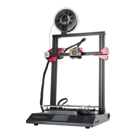
FDM 3D printer - BT1.2 model
Operating Manual

Operating Manual for 3D Printer BT1.2
2
CONTENT
1. Introduction
2. Technical specifications
2.1 Device description
2.2 Technical specifications
2.3 Description of individual parts
2.4 Package Contents
3. Safety instruction
3.1 Operator's obligations
3.2 Electrical equipment operation
3.3 Personnel without professional electrical qualification
3.4 Electrical equipment
3.5 Disposal of the product and its parts
3.6 Operator safety instructions
4. Printer assembly and connection instructions
4.1 Equipment construction assembly (mechanical part)
4.2 Connection (electrical part)
4.3 Commissioning
5. Printer
5.1 Starting printing - programme (* .gcode)
5.2 Pad calibration
5.3 Introduction of a new printing string - filament replacement
5.4 Restarting the printer - RESET
5.5 Turning the printer off
6. Maintenance
6.1 Moving parts
6.2 Printing pad
6.3 Print head (extruder)

Operating Manual for 3D Printer BT1.2
3
1. Introduction
This operating manual contains device technical data, data and instructions for its
assembly, as well as information concerning device operation and commissioning.
However, the manual could not fulfil its aim if its contents are not familiar to those
who operate and maintain the device.
It is the user and operator's responsibility to familiarise themselves properly with
these operating instructions before commencing work. It contains important
information on work safety and maintenance, and therefore must be considered
as part of the equipment. The device's fault-free, safe operation and also its service
life largely depends on its correct use and maintenance.
Any arbitrary changes made to this device without the manufacturer's permission
void the manufacturer from liability in relation to consequential damage or injury!
If you find it difficult to understand any information in this manual, contact the
device manufacturer. We recommend that you keep the original instructions safe.
When working, follow the safety instructions to avoid the risk of injury either to
yourself, or others around you.
These instructions are marked with the following safety warning symbols in
the operating instructions:
▪CAUTION RISK TO HEALTH OR DAMAGE TO PROPERTY
▪CRUCIAL INFORMATION FOR THE OPERATOR
▪GENERAL INFORMATION FOR THE OPERATOR
▪RISK OF HAND INJURY
▪CAUTION HOT SURFACE

Operating Manual for 3D Printer BT1.2
4
2. Technical Specifications
2.1 Device description
The device is delivered in kit-form, it is already partially assembled
and unconnected. Instructions for installation and correct connection
are part of this manual. Stepper motor drivers are already set to
optimal values, there is no need to set anything. The extruder nozzle
is tightened by heat.
The BT1.2 3D printer is designed as a single-purpose device for melting
and controlled plastic lamination - a process also called FDM (Fused
Deposition Modelling or FFF-Fused Filament Fabrication), and is a
common 3D printing technology.
This device is basically a computer-controlled machine.
2.2 Technical Data
Description
Value
Version
BT1.2
Producer
BART-TECH 3D s.r.o.
Height
639 mm
Width
459 mm
Length
559 mm
Weight
9.3kg (without printing string-filament)
Voltage source
180-264 V AC 47-63 Hz/ 12 V DC / 250W
Operating voltage
12 V DC
Operating temperature
range
18 to 38° C
Maximum humidity
85%
Nozzle temperature
max. 255° (recommended 210° -230° C)
Pad temperature
max. 110° (recommended 70° -90° C)
Print space (w x d x h)
220 x 220 x 240 mm
For materials
thermoplastic filaments Ø1.75 mm with a melting point up
to 250°
(PLA, PETG, HIPS, ABS, WOOD, NYLON, HIPS, ASA, ..)
Printing pad
magnetic + steel plate with PEI surface
Extruder
Dual drive
Control board
Makerbase MKS GEN L V1.0
Resolution of stepper
motors
400 steps / revolution (0.9° step angle)
The identification plate with a serial number is located on the rear of the aluminium profile.
Charged voltage: 230V / 50Hz, Max. current: 2.8 A

Operating Manual for 3D Printer BT1.2
5
2.3 Description of individual parts
Filament spool holder
Control unit MKS GEN L V1.0
Y-axis motor
Y
Extruder
Y
DC 12V power supply
230V mains
cable
connector
with 10A
fuse
Touch control panel
Z2 axis motor
Z1 axis motor
X-axis motor
nuts for
adjusting
the pad
height
Trapezoidal
movement
screws
Z-axis guide
rods
2x End switch
of Z1 axe on
the left, Z2 on
the right
X-axis limit
switch
Heated
magnetic
printing pad
with a PEI
surface
Y-axis belt
tensioner
X-axis belt
tensioner
Y-axis
guide rods
Aluminum frame
X-axis
guide rods
Anti-vibration
pads
main
switch
USB connector
(PC connection)

Operating Manual for 3D Printer BT1.2
6
Printhead - EXTRUDER
motor E
filament feed
wheel
filament pressure
wheel
compression spring
adjustment screw for
the pressure force on
the pressure wheel
heatblock
nozzle
blowing nozzles
ventilator FAN2
heatbreak
cooler
ventilator FAN1
pressure door
extruder body 1
extruder body 2
heater hole
temperature sensor
hole

Operating Manual for 3D Printer BT1.2
7
2.4 Package contents
•instructions for use and installation
•completely assembled lower frame including cables… 1 piece
•display including cover, brackets and connecting material… 1 piece
•completely assembled X axis including extruder and cables… 1 piece
•aluminium profile 20x40x400….. 2 pieces
•plastic holder for power supply 12V….. 1 piece
•aluminium corner connector…. 2 pieces
•upper part of the frame
•hardened guide bar 8h6 x 400…. 2 pieces
•movement screw with trapezoidal thread TR8x2… 2 pieces
•voltage source 230V / 12V incl. cables…. 1 piece
•mains (PC) cable with plug 230 V… 1 piece
•cabinet with control board and fan… 1 piece
•Allen key 2.5… 1 piece
•flat screwdriver 3mm… 1 piece
•Allen key 3… 1 piece
•Allen key 2… 1 piece
•flat nozzle wrench size 7… 1 piece
•flat nozzle wrench size 20… 1 piece
•side splitting pliers
•connecting material (part of each component)
•electrical cable ties… 6 pieces
•SD card

Operating Manual for 3D Printer BT1.2
8
3. Safety Instructions
Using this device in any way other than that specified by the manufacturer is contrary to its purpose!
Any arbitrary changes made to this device without the manufacturer's permission void the
manufacturer from any liability for consequential damage or injury! When working, follow the
safety instructions to avoid risk of injury to either yourself or others around you. Use extreme
caution when handling the printer, as this is an electrical device with moving and high-temperature
components.
The printer is designed for indoor use. Place the printer in a stable, clean place at a suitable
distance from other objects. There must be no flammables or explosives within reach.
Before connecting the printer with the power cable to a 230V, 50Hz power outlet, make sure that
the cable is not mechanically damaged. Replace a damaged cable immediately.
Do not touch the nozzle or heated pad when the printer is running. The surface temperature can
be up to 100 °C depending on the type of printing and the nozzle temperature up to 250 °C.
Never disassemble the printer's power supply. In the event of a malfunction, always hand the
printer over to a qualified service technician or contact the manufacturer. Use extreme caution
when operating the printer.
The device has a number of moving and rotating parts, which could result in injury if handled
incorrectly. Touching these parts during operation is forbidden.
The printer must not be left unattended when running.
The printer produces fumes and odours due to melting plastic, so place the printer in a well-
ventilated area without drafts. Drafts have a negative effect on the print quality.
3.1 Operator's obligations
(Operator's obligations related to equipment maintenance in accordance with applicable regulations
and standards)
➢maintain electrical equipment in a permanently safe and reliable condition in accordance with the
applicable electrical regulations
➢make sure that electrical equipment is not tampered with by people without electrotechnical
qualifications (lay people) and that they do not carry out work in accordance with applicable standards
and regulations
➢demonstrably acquaint all personnel who operate the electrical equipment in question with the
operator and safety regulations, and also with the possible risk of electric shock
3.2 Electric Equipment Operation
(equipment operation requirements in terms of electrical equipment qualification)
➢only personnel with the required qualifications may operate electrical equipment
➢people without professional electrical qualification (laymen) can operate small and low voltage
electrical equipment which are designed so that they cannot come into contact with exposed live parts
of electrical equipment during their operation
➢if local or other safety and work regulations or instructions are drawn-up, they must be accessible in a
suitable place, and staff must be demonstrably acquainted with them
➢people operating the equipment must be familiar with the equipment being operated and its function
➢the operator can only touch parts that are intended for the operator
➢there must always be free access to serviced parts
➢in the event of damage to electrical equipment or a failure that could endanger an employee's
health and safety, the employee who detects such a condition and who is unable to eliminate the

Operating Manual for 3D Printer BT1.2
9
cause of the danger themselves must take measures to prevent or reduce the risk of injury, fire or
other hazards.
➢electrical appliances must be safely disconnected from the power supply before moving
3.3 People without professional electrical
qualifications
(requirements for operating equipment in terms of electrical equipment qualifications)
➢before moving electrical equipment connected to the mains by flexible cable and a plug, safe
disconnection from the mains must be done by taking the plug out of the socket.
➢when operating electrical equipment, the operator must observe the relevant instructions as well as
local operating regulations for its use, and also make sure that the equipment is not excessively
overloaded or otherwise damaged.
➢maintain electrical equipment in accordance with the manufacturer's instructions
➢only replace remelted inserts of threaded and instrument fuses with new inserts of the same value
(remelted inserts must not be repaired)
➢when the electrical device is switched off, they can move and extend the movable leads with
connecting cables provided with appropriate connecting parts
➢switch simple electrical devices on and off
➢if the operator notices a fault in the equipment, e.g., damage to insulation, burning odour, smoke,
unusually noisy or shock operation of electrical equipment, strong humming, jerky start, some
electrical equipment part overheating, sparks, armour from electric current, THE ELECTRICAL
EQUIPMENT MUST BE SWITCHED OFF IMMEDIATELY!
3.4 Electrical equipment
(equipment operation requirements)
➢DAMAGED ELECTRICAL EQUIPMENT MUST NOT BE USED!
3.5 Disposal of the product and its parts
(equipment disposal ecology)
OBSERVE APPLICABLE ECOLOGICAL REGULATIONS!
When the equipment is eventually decommissioned (at the end of its service life), bear in
mind the environmental protection and recycling options (in general):
➢dispose of toxic waste (e.g., batteries, electronics), separate plastic materials in accordance
with regulations and offer them for recycling
➢separate metal parts for scrapping in accordance with the type
➢it is necessary for the facility owner to comply with the Waste Act when disposing of waste in
terms of care for healthy living conditions and environmental protection
➢it is necessary for generated waste to be offered to waste disposal facility operators,
particularly metals, oils, lubricants, plastics, etc.

Operating Manual for 3D Printer BT1.2
10
3.6 Operator Safety Instructions
(the device operator must follow these instructions)
THE EQUIPMENT'S ELECTRICAL PARTS MUST NOT BE RINSED WITH WATER!
➢Safety elements must always be kept in perfect condition
➢Keep the device safety markings legible
➢Be sure to follow this manual's safety instructions
➢Read these operating instructions, including other instructions for any sub-equipment, carefully before
using the device in any way.
➢If the device begins to shake strongly, shows increased noise or other abnormalities during operation,
turn it off and have it checked immediately.
➢Do not start the device without covers
➢damaged equipment must never be used
➢the equipment must only be used for the purposes for which it was designed
➢only work in good lighting conditions
➢Before starting work, the operator must perform a visual inspection on the equipment's moving parts
for signs of excessive wear or damage.
➢This device cannot be used with excessively worn or damaged parts
➢Only carry out device maintenance and cleaning when the power supply is disconnected
➢This device may only be operated by people over 18 years of age, who are mentally and physically fit,
well acquainted with its properties and familiar with the relevant regulations for its operation.
Younger people may only operate the device under the supervision.
➢It is forbidden to operate the device under the influence of alcohol, drugs or other narcotics
➢All device maintenance and repairs must only be carried out with the device stopped and properly
secured
➢The device is intended for indoor use only (premises)

Operating Manual for 3D Printer BT1.2
11
4. Printer assembly and connection instructions
4.1 Equipment construction assembly (mechanical
part)
1
2
3
4
5
6
6
7
8
Overview of the main assembly steps:
1. fasten both aluminium profiles
2. slide both guide rods into the
brackets
3. install the x-axis
4. tighten both movement bolts
5. fit the frame's upper part
6. attach the power supply
7. attach the control board unit
8. attach the coil
9. attach the control panel
(See details in the manual's other pages)
9

Operating Manual for 3D Printer BT1.2
12
Slide the profile in until it is in contact with the opposite profile. Hold down and gradually tighten all the bolts in the order
numbered in the picture above. The same applies for both sides.
Tighten the M4 bolt with T-nut (applies to all connections of plastic parts to the aluminium profile)
Insert the rod to the bottom of the hole. Tighten both bolts. The same on both sides
1
T-nut's initial
position when
assembling the
parts together
loosen the bolt so that the T-nut rests on the bottom of
the profile groove
tighten the bolt (T-nut rotates itself in the
profile groove)
Incorrect
Correct
2
after tightening
after tightening
1
2
3

Operating Manual for 3D Printer BT1.2
13
Place the assembled X-axis with sliding bearings on the mounted guide rods. Hold the axis, do not let it fall down by itself!
Hold the X axis raised and turn the movement bolt into the brass nut. Carefully lower the bolt to the motor coupling, where
it reaches the motor shaft. Tighten both bolts on the coupling. Repeat in the manner on the other side.
3
4

Operating Manual for 3D Printer BT1.2
14
Put the upper part of the frame on, put on the profile and check that the entire surface is seated correctly on both sides.
Tighten the 2 M4 bolts with T-nuts (both sides). Tighten the M3 bolts in the rod holder twice (both sides). Attach the corner
connector and tighten both M4 bolts with T-nuts
The cover with the power supply put on the vertical stand and the lower black console. Tighten the M4 bolt. Adjust the
upper power supply bracket height to the threaded hole and tighten the M3 bolt.
5
Loosen
these bolts
before
installing
the bracket.
6
corner connectors location
bracket height adjustment

Operating Manual for 3D Printer BT1.2
15
7
8

Operating Manual for 3D Printer BT1.2
16
9
tighten 4 M4 bolts with T-nuts

Operating Manual for 3D Printer BT1.2
17
4.2 Connection (electrical part)
Control board description
Overview of the main steps with concern to the control board connection:
1. 12V voltage source
2. heated pad (heating, temperature sensor TB)
3. extruder (motor E, heating, temperature sensor TH, ventilators FAN1 and FAN2)
4. stepper motors X, Y, Z1, Z2
5. limit switches X, Y, Z1, Z2
6. LCD - LCD12864 display
7. fix the cable outlets from the cabinet with cable ties
8. connect the FAN0 ventilator in the cabinet cover
(For details, see the photo instructions on the following pages)
input voltage 12V
(for power supply)
- +
+ -
output voltage 12V
heated pad
+ -
+ -
output voltage 12V
extruder heater
output voltage 12V
fan FAN1-hotend
output voltage 12V
fan FAN2-blower nozzle
X-axis motor connection
Y-axis motor connection
Z1 axis motor connection
motor connection E (extruder)
Z2 axis motor connection
USB connector
computer connection
cable hole (extruder
and heated pad)
cable hole (other cabling)
RESET button
LCD TFT28/32 port for
BT1.2 model
limit switch X
End switch Z2
limit switch Y
limit switch Z1
pad temperature sensor
nozzle temperature sensor
tunnel for cable routing
ventilator FAN0 - active
cooling the control
board

Operating Manual for 3D Printer BT1.2
18
Power supply connection to the control board
Connect both contacts to the terminal block, carefully tighten with a flat-blade screwdriver and check the tightness by
pulling. Check the polarity carefully! Front view of the board = left BLACK (-) and right RED (+)
When tightening, hold the terminal block against movement with two fingers. Place the cables in a tunnel around the
board.
!!! CAUTION the control board may get damage in case of incorrect connection or reversing the
polarity!!!
1
gradually insert the supply
cable from the source into the
lower cable holders (plastic
lugs).

Operating Manual for 3D Printer BT1.2
19
Heated pad connection
The printing pad wiring harness has heated contacts (red + black) and a temperature sensor connector on the black wires.
There is a reinforced brace in the cable harness.
Connect both contacts to the "HBED" terminal block, carefully tighten with a flat-blade screwdriver and check the
tightness by pulling.
Front view of the board = left Red (+) / right Black (-).
When tightening, hold the terminal block against movement with two fingers.
Place the red and black thick cables in the cable tunnel again on the left along the board
Connect the temperature sensor connector (white socket "TB" on the bottom left of the board). Compare all the cables to
the tunnel. Before fixing the cable with a cable tie, turn the cable clockwise and pre-tension the cable so that it does not
touch the frame when moving the pad. Cut off the cable tie excess.
2
TB

Operating Manual for 3D Printer BT1.2
20
Extruder connection
3
end of extruder
harness
FAN1 connector
–longer cable
FAN2 connector
–shorter cable
extruder heating contacts
(heater)
motor
connector E
temperature sensor connector
trysky
Connect both contacts to the "HE0"
terminal block, carefully tighten with a
flat-blade screwdriver and check the
tightness by pulling. Polarity does not
matter.
Connect the motor connector
(marked "E") to the socket on the
board marked "E0"
Connect the temperature sensor
connector to the socket on the
board marked "TH1"
Connect the FAN1 connector to the
cable splitter socket (this is already
connected to the "HE1" terminal
block). FAN1 connector is on a longer
cable.
Connect the FAN2 connector to the
"FAN" socket on the board. FAN1
connector is on a longer cable.
After connecting all the contacts,
hide the cables in the side tunnel.
Secure the cable harness with cable
tie over the cable from the heated
pad. Before tightening, pre-tension
the cable again (turn it clockwise).
Cut off the cable tie excess.
Optimal cable formation from the
control unit. They are not in contact
with the frame or pad when moving
E
TH
Note: There is a reinforcing brace in the cable
harness.
Table of contents
