Airwolf 3D AW3D HD User manual

2 | P a g e
Table of Contents
Specifications .............................................................................................................................................. 4
Unboxing the Printer................................................................................................................................... 5
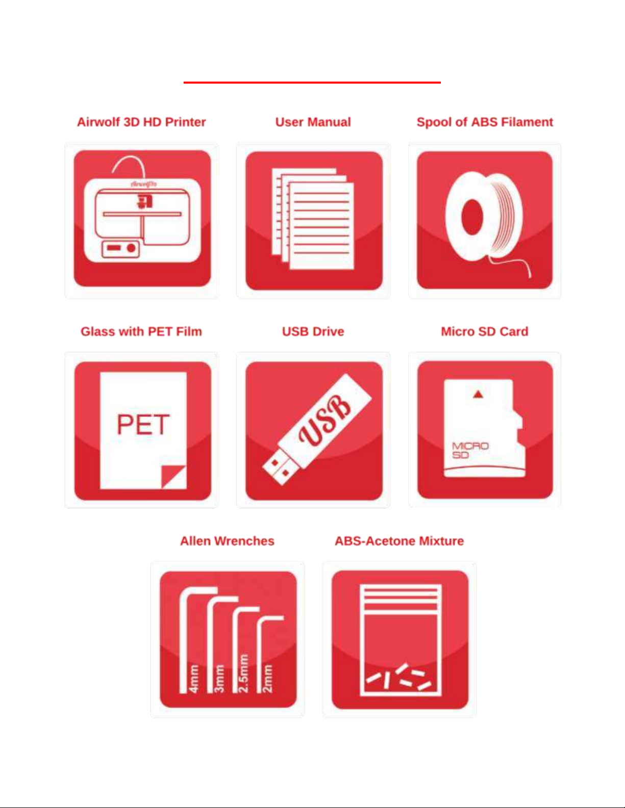
Box Contents ........................................................................................................................................... 5
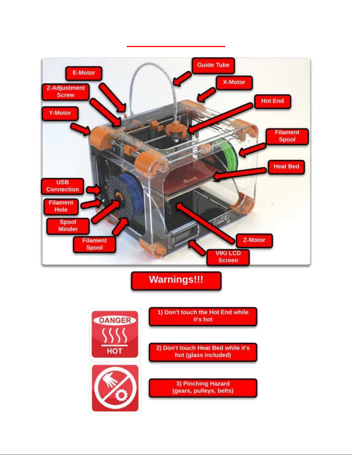
Part Directory.............................................................................................................................................. 6
How it Works............................................................................................................................................... 7
Extruder Assembly .................................................................................................................................. 7
Hot End and Heat Bed Motion ................................................................................................................ 7
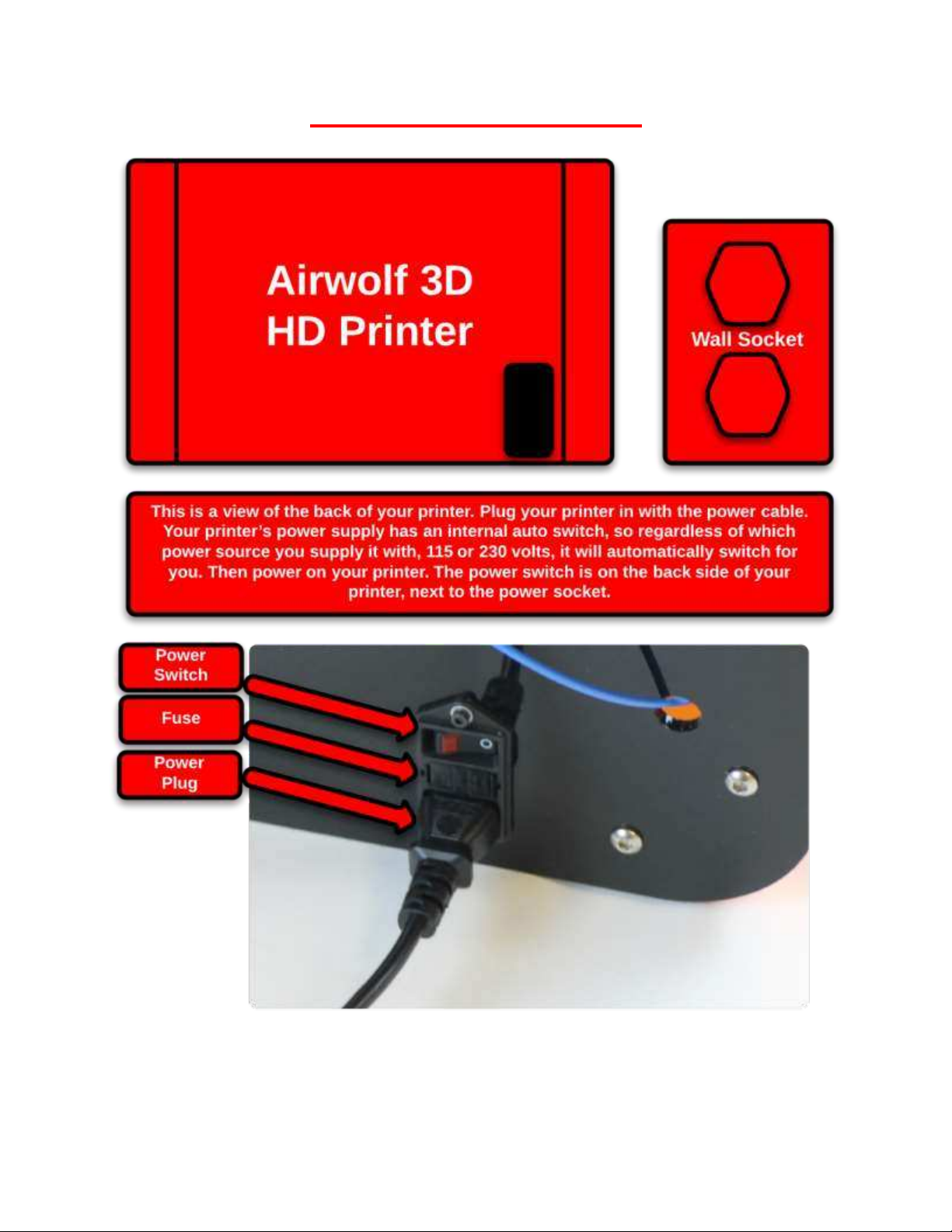
Plug In & Turn On........................................................................................................................................ 8
Pre-Printing Steps ....................................................................................................................................... 9
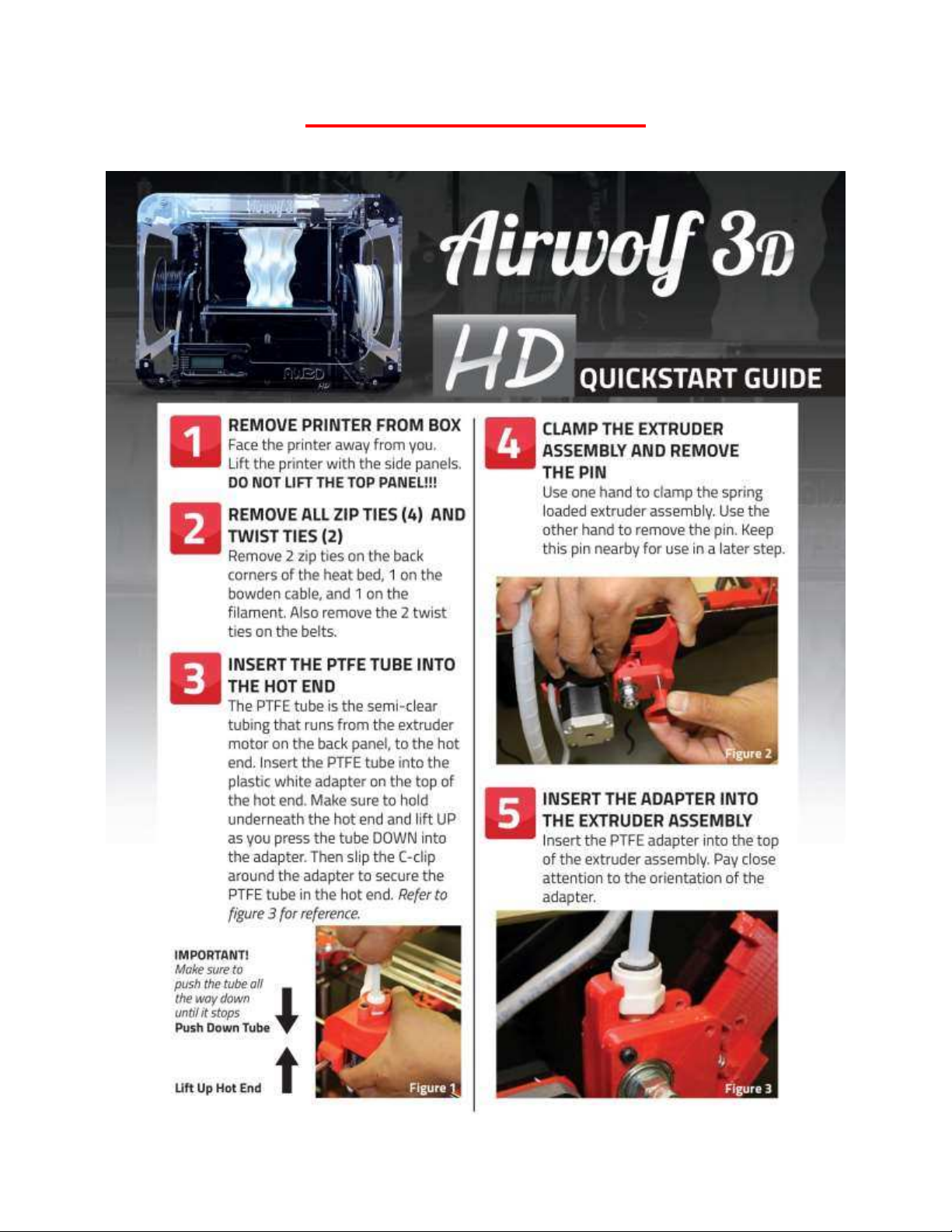
Quick Start Guide .................................................................................................................................... 9
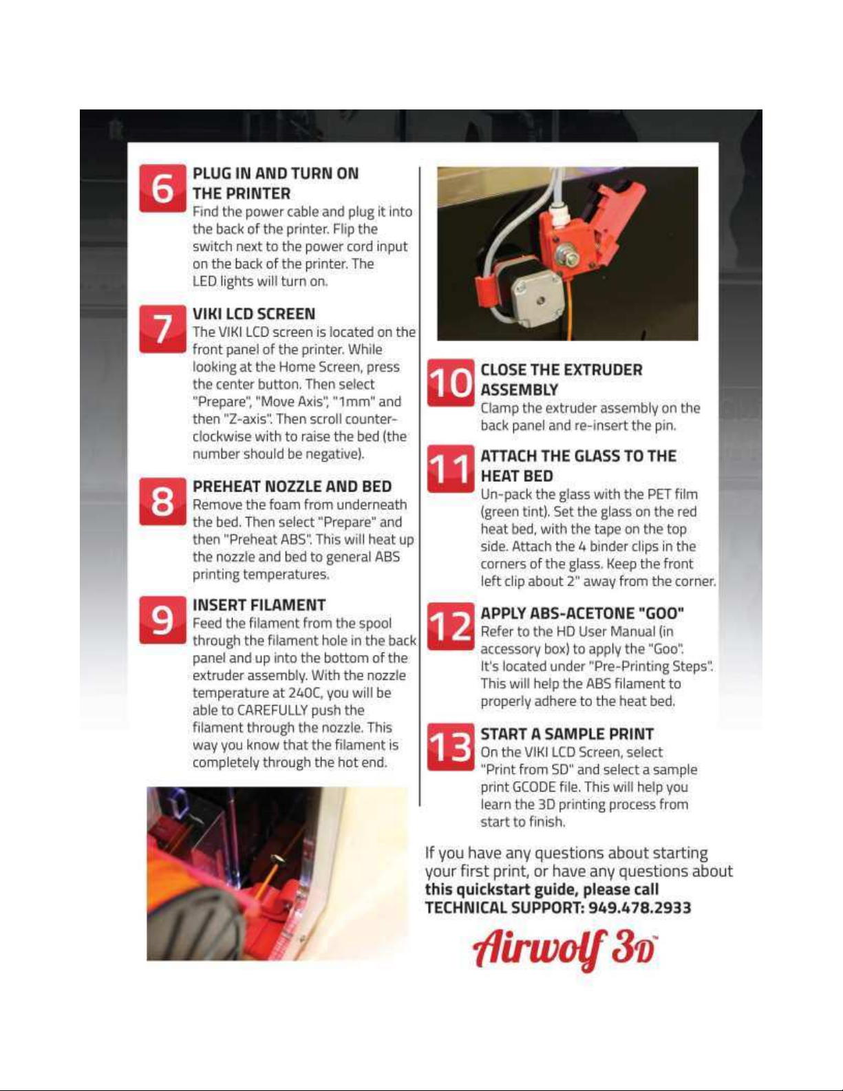
Quick Start Guide (contd.)..................................................................................................................... 10
1) Leveling the Heat Bed ....................................................................................................................... 11
First Print & Calibration......................................................................................................................... 12
First Print & Calibration (contd.) ........................................................................................................... 13
2) Loading Filament............................................................................................................................... 14
E G O‘ GOO........................................................................................................................ 15
4) The First Layer ................................................................................................................................... 15
5) LED Lights .......................................................................................................................................... 15
VIKI LCD Screen ......................................................................................................................................... 16
VIKI: Introduction .................................................................................................................................. 16
VIKI: Home Screen................................................................................................................................. 16
VIKI: Layout............................................................................................................................................ 17
VIKI: How To .......................................................................................................................................... 18
RAMBo Driver ........................................................................................................................................... 19
Setup (Windows 8 Only)........................................................................................................................ 19
Installation (PC Only)............................................................................................................................. 20
5 Steps to Printing..................................................................................................................................... 23
1) Download or Design a 3D Model ...................................................................................................... 24
2) Convert to STL File Type.................................................................................................................... 25
3) Netfabb: Layout (STL Clean Up) ........................................................................................................ 25
3) Netfabb: How To (STL Clean Up)....................................................................................................... 26
4) Slicing ................................................................................................................................................ 27

3 | P a g e
Slicing: Breakdown ................................................................................................................................ 28
4-5) MatterControl PRO: How To.......................................................................................................... 29
4-5) MatterControl PRO: How To (contd.) ............................................................................................ 30
4-5) Repetier Host: Setup...................................................................................................................... 31
4-5) Repetier Host: The Basics .............................................................................................................. 32
4-5) Repetier Host: How To................................................................................................................... 33
4-5) Repetier Host: How To (contd.) ..................................................................................................... 34
Material Selection..................................................................................................................................... 35
Materials: Comparison.......................................................................................................................... 35
Materials: Comparison (contd.) ............................................................................................................ 36
Materials: Settings................................................................................................................................. 37
Materials: Settings (contd.)................................................................................................................... 38
Post Processes........................................................................................................................................... 39
Acetone Vapor....................................................................................................................................... 39
Two Part Epoxy...................................................................................................................................... 40
Firmware ................................................................................................................................................... 41
Maintenance ............................................................................................................................................. 42
Belt Tensioning...................................................................................................................................... 43
Rod Alignment (X-axis) .......................................................................................................................... 44
Rod Alignment (Y-axis) .......................................................................................................................... 45
Rod Lubrication ..................................................................................................................................... 46
Inserting Filament ................................................................................................................................. 46
Wiring Diagram ..................................................................................................................................... 47
Clogged Nozzle ...................................................................................................................................... 48
Changing the Nozzle.............................................................................................................................. 49
Trouble Shooting....................................................................................................................................... 50
Glossary of Terms ..................................................................................................................................... 51
Hardware............................................................................................................................................... 51
Software ................................................................................................................................................ 51
Contact List ............................................................................................................................................... 51
Notes......................................................................................................................................................... 52
Notes......................................................................................................................................................... 53

4 | P a g e
Specifications
Copyright 2013 ©
Designed and
Manufactured In:
12 x 8 x 12 inch
300 x 200 x 300 mm
24 x 17.5 x 18 inch
610 x 445 x 460 mm
38 lbs
17 kg
Material that can
be printed:
Filament
Diameter
Nominal: 3.00mm
Actual: 2.85 ± 0.1mm
mm
Nozzle Diameter 0.5 and 0.35 mm
0.06 mm
0.0024 inch
150 mm/s
5.91 inch/s
400 mm/s
15.75 inch/s
Circuit Board
Bed
Frame
Display
Power Supply
File Format
System
Compatibility
Matter Control & Repetier-Host
Cura & Slic3r
RAMBo
Temp Controlled Heated Bed
Comp.
Software
Netfabb & MeshLab
Windows, Mac, Linux
STL & GCODE
General
Partially Enclosed Acrylic
VIKI LCD Screen
Hard
ware
Printer Size
(LxWxH)
Internal auto-switching 13.5V DC, 300W
Weight
USA
ABS, PLA, Soft PLA, PLA 4043D, BendLay,
LayWOO D-3, Laybrick, HIPS, T-Glase,
PVA, Nylon, TPE & more to come!
Build Volume
(LxWxH)
Minimal Layer
Thickness
Max Speed-
Perimeter
Max Speed-
Travel
Specs.

5 | P a g e
Unboxing the Printer
Box Contents

6 | P a g e
Part Directory

7 | P a g e
How it Works
Extruder Assembly
Hot End and Heat Bed Motion

8 | P a g e
Plug In & Turn On

9 | P a g e
Pre-Printing Steps
Quick Start Guide

10 | P a g e
Quick Start Guide (contd.)

11 | P a g e
1) Leveling the Heat Bed
Why Level the Heat Bed- One of the most important steps in 3D printing is how the first layer prints.
Like building a house, the first layer is the foundation for the remainder of your print. Without a level
bed, your print will be marginal at best. Because of the configuration of the printer, the heat bed only
moves slowly in the Z direction. This means that the heat bed tends to stay reasonably level over time.
The better the calibrated printer, the more efficient the printing process is. Calibrating the printer
should be done once a month or so and when traveling with the printer in a car. This will insure that
Basic Concept to Level the Heat Bed- There are two parts to leveling the heat bed. The first part is to
make sure that the XY plane (the plane that the nozzle moves in) is parallel to the heat bed (glass). This
is achieved by the four small M3 screws in each corner of the heat bed. The second part is the first
layer height. This is achieved by the Z-adjustment screw and limit switch subassembly for the heat bed.
The Z-adjustment screw is labeled on the Part Directory page. This spring loaded screw initiates the
limit switch (Z-min) and sets the first layer height.
Steps to Leveling the Heat Bed- On the micro SD card, there is a Calibration Print. Run this calibration
print to level the heat bed. There is also a video on our website that is a step by step guide along for
this calibration. We highly recommend that you run this print before trying to print out parts. Your
success rate is highly dependent on how level your heat bed is. The quick start guide will also have the
steps written out as well. The next two pages have a step-by-step guide for calibrating the printer.
Once you have calibrated the printer, we highly recommend that you run a few sample prints before
moving on to custom prints. This will ensure that the printer is working correctly. Also you will gain
valuable knowledge from this. For one, you will understand how the printer works before having to
dive into the settings. And secondly, you will have the opportunity to see some massive prints that
very few printers can print. Plus you get to show off to your family, friends, coworkers and boss the
incredible sample parts.

12 | P a g e
First Print & Calibration

13 | P a g e
First Print & Calibration (contd.)

14 | P a g e
2) Loading Filament
Good quality filament will be 2.85 ± 0.10mm in diameter. If the filament is consistently over 3.00mm,
you may want to purchase the material from somewhere else.

15 | P a g e
3) Elmers Glue OR GOO
For ABS prints, a PURPLE E G
bed. This is very important in keeping the part from warping or curling during the print. The PURPLE
E G on top of the PET film as the bed is heating up. It only needs to be
applied where you are printing your part.
GOO is a different way of helping your parts to stick. GOO is a solution of natural ABS sticks and
Acetone in a glass jar. The mixture in the jar should look murky. When your bed is heating up, saturate
a piece of paper towel and wipe the bed. This will be applied on top of the PET film (green) that is
already on your glass. The area of the glass where the GOO is applied should have a white frost look to
it.
EITHER USE THE PURPLE ELMERS GLUE STICK OR THE GOO, BUT NOT BOTH.
4) The First Layer
Why- The first layer is by far the most important layer of your entire print. If your first layer is
successful, you have a very good chance of having a successful print. The first layer height is controlled
by the Z-adjustment screw which is spring loaded and in the back left corner of the top panel. The bed
raises and initiates the limit switch to set the first layer height. Once your bed is level, there are a
couple steps to getting a good first layer.
How To- First turn the Z-height-adjustment screw clockwise a half turn with your 2.5mm allen wrench.
Next, move your nozzle to the center of your bed. Then home the Z-axis. The bed will raise and initiate
the limit switch. At this point, the nozzle should be off the bed. Turn the Z-height-adjustment screw
counter clockwise a quarter turn. And once again home the Z-axis. Repeat this process until your nozzle
is just off the bed.
Nozzle Too High- If you run a print with the nozzle too high, the filament will just lie on the glass and
not stick. Turn the Z-adjustment screw counter clockwise. This means the Z limit switch to be activated
later, and there for the nozzle is closer to the glass. Home the Z again and repeat until the nozzle is just
off the bed.
Nozzle Too Low- If you run a print with the nozzle too low, the filament will have no room to come out
of the nozzle and seem to clog. If this does happen, raise the nozzle off the bed at least 3 inches, make
sure your nozzle is heated to at least 245C, and extrude material. Then turn the screw clockwise. Home
the Z again and repeat until the nozzle is just off the bed.
Nozzle Height is Just Right- The first layer should look like a pancake. The nozzle should be extruding
the material and smooshing it into the glass.
***This can be done during the first layer of the print with the Z threaded rod (the threaded rod
attached to the Z-motor). This assumes that the bed has already been leveled. If the nozzle is too close
to the glass, turn the Z threaded rod counter clockwise to lower the bed. If the nozzle is too far from
the glass, turn the Z threaded rod clockwise to raise the bed. This should be no more than 1/8 of a turn
or so. NOTE that this action will only offset the first layer for the current print. If run again, the
adjustment will not have effect.
5) LED Lights
The LED lights will turn on automatically when your print starts and turn off when your print ends. But
you can manually turn on the lights. M P “ , M P “ m off.

16 | P a g e
VIKI LCD Screen
VIKI: Introduction
Out of the many features the VIKI LCD Screen has, there are four main ones that you will use regularly.
They include Auto Home, Preheat ABS, Move Axis and Print from SD. The following page has a layout
of all the features the VIKI has to offer and these four functions are underlined.
Auto Home- Auto Home (AKA the origin) will use the min limit switches to move the nozzle to the front
left corner, and the bed to the top. Home is very important because that is where every print will start
from.
Preheat ABS- Preheat ABS is a great feature for preheating your printer before printing. When you are
done designing, slicing, and loading your SD card, your printer is ready to go.
Move Axis- Move Axis allows you to manually move the nozzle and bed in each direction.
Print from SD- Print from SD is where you can access the GCODE files on your micro SD card. We have
already loaded a library of sample prints for you to run right away.
VIKI: Home Screen
This is the home screen for the VIKI LCD Screen. There are two heated components on the printer, the
nozzle and the bed. Both actual and target temperatures are displayed. T PO“ITION
T FEED ‘ATE A
printer is running exactly what the GCODE is instructing it to do. If the feed rate is increased or
decreased, the printer will speed up or slow down in every direction. To change the federate, turn the
dial on the VIKI home screen and watch the percent change. It is not recommended to go any faster
when using the fast settings. The SD Card _ _% is how full your micro SD Card is. T T
amount of time that the printer has been printing its current job.

17 | P a g e
VIKI: Layout

18 | P a g e
VIKI: How To
The four main functions of the VIKI LCD screen are to prepare for a print, manual control, run a print
and control the printer during a print. Use the layout on the previous page as a road map to find each
function. To go from row to the row, simply click the center button. Use the scroll wheel to move left
and right in the road map. If left idle for 15 seconds, the VIKI will return to the home screen.
Prepare- T P A H P AB“ M A
A H direction (X, Y, Z). The
home for the printer is essentially the origin in the XYZ coordinate system. P AB“
both heaters for the extruder and bed to near the printing temperatures of ABS. This way, when your
start your print, the temperatures may just have some minor changes if needed.
Manual Control- U P M A O
extruder and bed can be manually controlled by the user. This also includes the extruder. This function
can be used to purge the machine of a previous material or color. When changing materials, purge
between 500 and 1000mm to completely get rid of the old material. (Also see the material section for
further instructions about different materials)
Print from SD- P “D GCODE O “TL
GCODE is created, it can be saved onto the micro-SD card. Keep in mind that once a part is sliced, that
GCODE file is for a specific material (temperatures, speeds, etc.)
Tune- There are a few things that can be altered during the print by using the VIKI LCD screen. One of
them is speed or feed rate. This will speed up or slow down a print. The rule of thumb is not to go any
faster than fast settings and not any slower than slow settings. At 100%, the printer is running the
GCODE exactly, utilizing the settings. Above 100%, the printer will increase its speed; below 100%, the
printer will decrease its speed. It is not recommended to increase the feed rate higher than 125% or
lower than 75%. This is mainly because of the retraction in the bowden system. The other way to
increase or decrease the speed during a print is to spin the wheel while looking at the home screen;
this will cause the feed rate value to change accordingly. The nozzle and bed temperatures can also be
altered during the print. Some times for big or tall parts, it may be useful to increase the bed
temperature a little. The fan speed is only used for materials that would require fans (refer to
M “ ABS does NOT need the fans.

19 | P a g e
RAMBo Driver
Setup (Windows 8 Only)

20 | P a g e
Installation (PC Only)
1) Only PC computers need the RAMBo Driver.
2) Plug your printer into your computer with the USB cable. Also insert the Airwolf USB stick
provided with the printer.
3) I C P D P U U
‘AMB ‘ P
4) A U H P
5) A U G U D
This manual suits for next models
1
Table of contents
Other Airwolf 3D 3D Printer manuals