TRONXY X5SA User manual

X5SA
Installation instructions
SHENZHEN TRONXY TECHNOLOG CO.,LTD
Aluminium profile 1
Aluminium profile 2
Aluminium profile 3
Aluminium profile 1
Aluminium profile 1
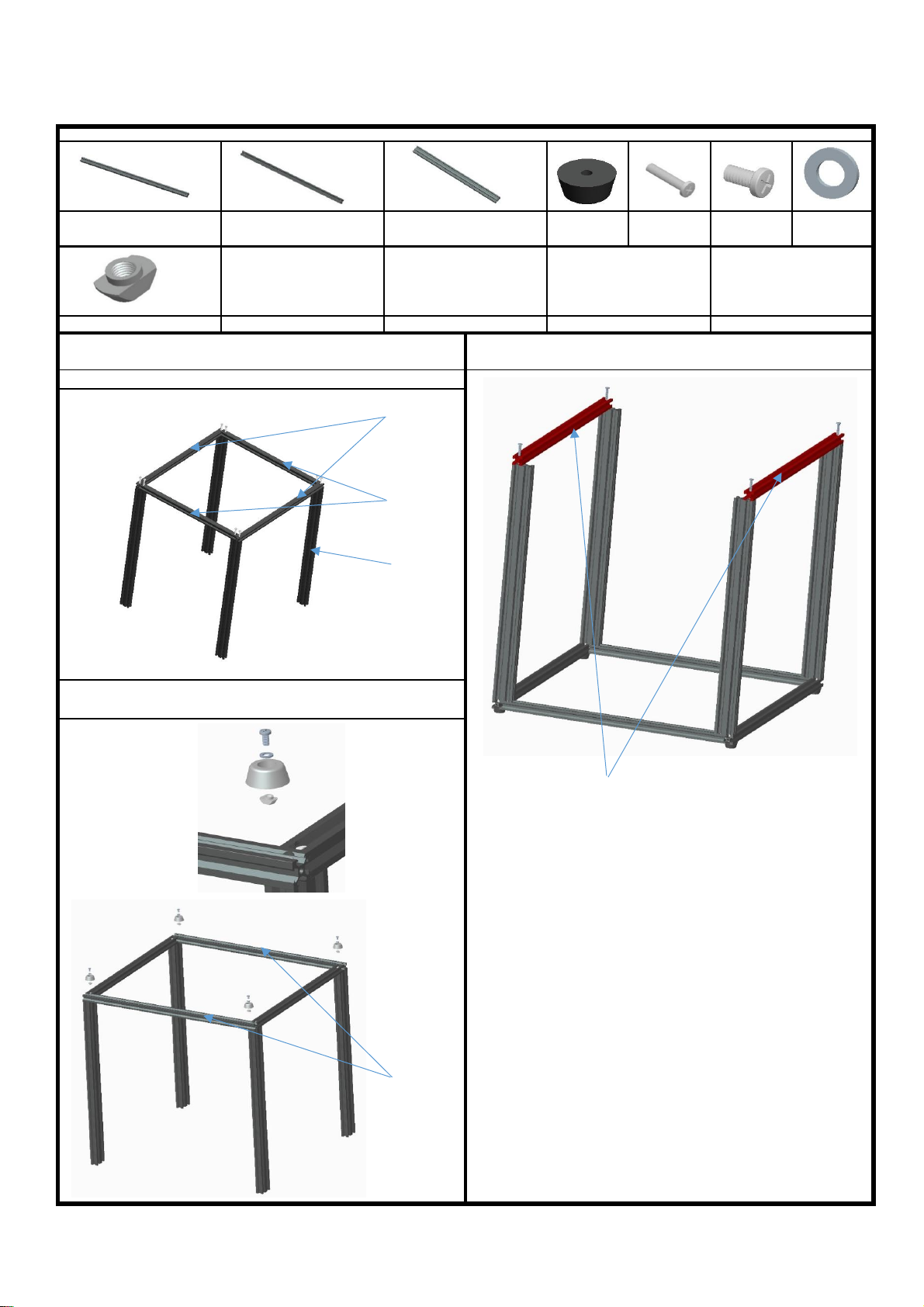
2.Assemble the pad, spacer, screw PM4*8, T nut M4 with the aluminium profile 1
together,distance from the end around 20mm, same as the illustration
Aluminium profile 1 20*20*530mm
4pcs
Aluminium profile 2 20*20*460mm
2pcs
Aluminium profile 3 20*40*530mm
4pcs
1.Lock the aluminium profile 1 2pcs, Aluminium profile 2 2pcs, aluminium 3 4pcs
together by 8pcs screw PM5*25, same as the illustration.
Note: Before locking the screws, make sure the aluminum profile are aligned and vertical
Step 1. Assemble base frame
Assemble parts specifications and quantity:
T nut M4 4pcs
3.Lock the aluminium profile 1 2pcs with 4pcs screw PM5*25
Note: Do not tighten too much, enable they can be adjusted in further step.
Pad 4pcs
Screw PM5*25
12pcs
screw PM4*8
4pcs
Spacer M4
4pcs
1 Product assembly

Slider plate(Left) Slider plate(Right)
Step 2:Assemble slider plate
Slider plate (Left) 1pcs
Slider plate (Right) 1pcs
2. Put 2pcs aluminum 2, through Left and Right slider plat
component respecitve, as same as the illustration.
Note: The wheels are on the side without holes, the slide plate is
on the side with the four holes.
Assemble parts specifications and quantity:
Alu. profile 2
20*20*460mm
2pcs
Screws
PM5*25mm
4pcs
PM4*8mm
screws 4pcs
M4 T nut
4pcs
1, Respectively insert 2pcs PM4*8mm screws to Left and Right slider
plate , lock with M4 T nut , as same as the illustration.
3.Put the aluminum 2 components into the end of the aluminum frame 3
of the bottom frame, then secured by 4pcs screw PM5*25, as same as
the illustration.
Aluminium Frame
Pay attention to the sink hole
The eccentric nut
Adjust pulley clearance by rotating eccentric nut

Slider plate(Right) Slider plate(Left)
PM3*16 PM4*12
Aluminium frame
M4 T-Nut
2pcs
Step 3:Assemble printing head
Assemble parts specifications and quantity:
Note:The distance between the aluminum 4 and aluminum 2 is 3mm
M3 Nut
4pcs
Towline holder
1pcs
PM3*16MM
2pcs
PM3*8MM
2pcs
PM4*12mm
2pcs
3, Assemble the Towline and the holder using 2pcs PM3*16mm
screws and M3 Nuts , then place the towline holder to the
aluminium profile as the illustration.
1, Place the towline to the printing heat , secure with 2pcs
PM3*8mm screws and M3 Nut
2.Insert the aluminum profile 4 into the printing head
component,same as the illustration.
The eccentric
nut
Adjust pulley clearance by rotating eccentric nut
4.Put the aluminum 4 component into the T nut of the left and right slide
plate component,screw the screw PM4*8 of the slide plate,same as the
illustration. Move the aluminum profile 4 front and back,make sure it can
move freely,then lock the screw PM4*8, remove the aluminum 4,ensure
it can move freely, lock the screw PM5*25 of the aluminum 2, move the
aluminum 4 again to make sure the movement is flexible. Lock the
screws PM5 * 25 of aluminum profile 2,move the aluminum 4 again to
make sure the movement is flexible, otherwise, please adjust it again,
make sure tthe sliding table is flexible and without gap shaking after
locking the screws
Alu. Profile 4
20*20* 484mm
1pcs
Printing head
component
(with Towline) 1pcs

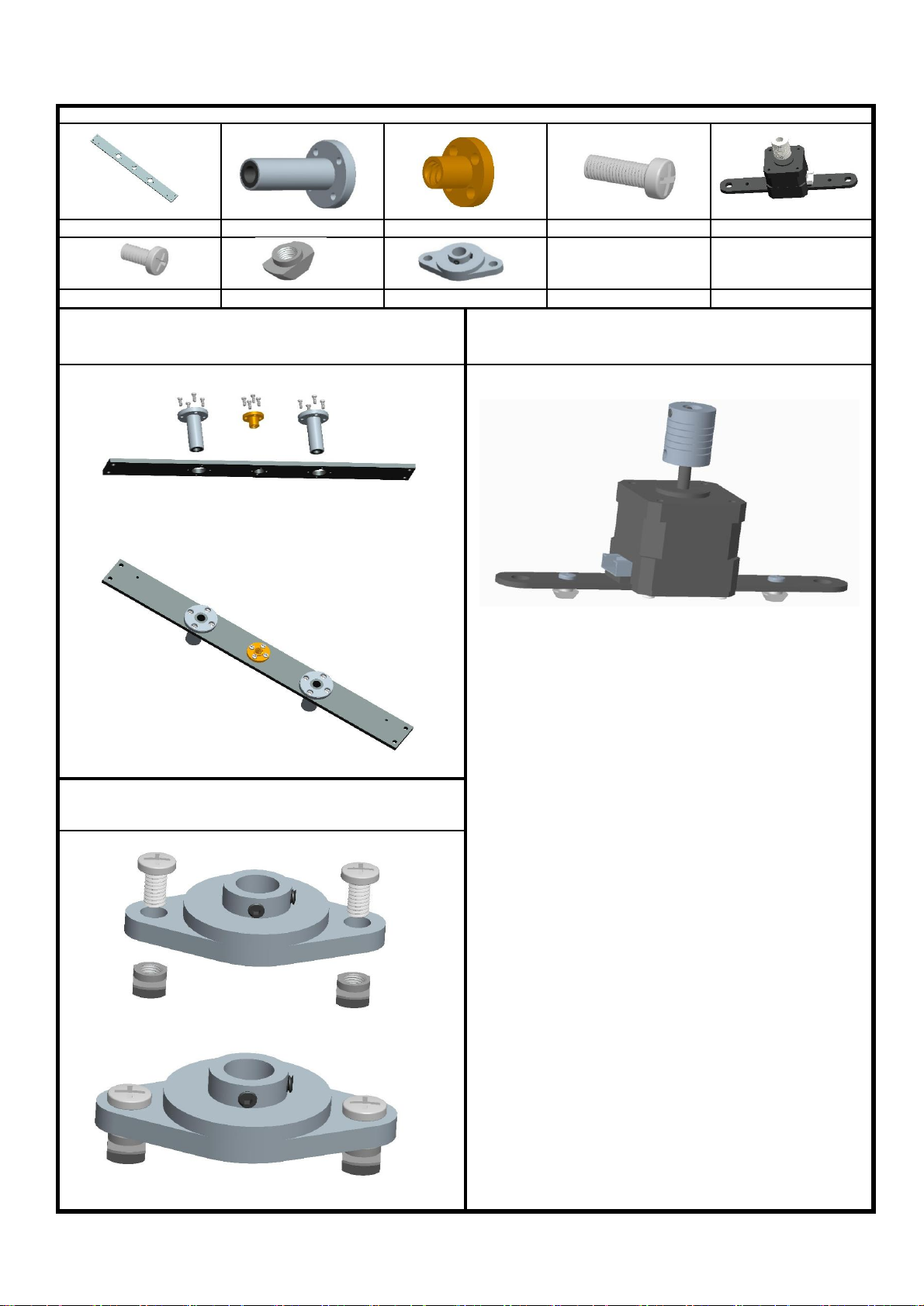
Step 4:Assemble XY axis motor and wheel
Assemble parts specifications and quantity:
X Motor base
plate 1pcs
M4 T-Nut
10pcs
Screws PM4*12
4pcs
2. Respectively insert 3pcs PM4*8mm screws to Left and Right pulley
component , lock with M4 T nut , as same as the illustration.
1. Assemble X & Y motor and X & Y motor base plate using 4pcs
PM3*10mm screws , Respectively insert 2pcs PM4*12mm screws to the
plates , lock with M4 T nuts , see the illustration
3.Fix the X motor component,Y motor component,left pulley
component,right pulley component and aluminum by PM4*12mm screws
and M4 T nut, as same as the illustrations.
Screws PM3*10
8pcs
Y Motor base
plate 1pcs
Framework
Pulley component
(Right) 1pcs
Pulley component
(Left) 1pcs
Motor 2pcs(With
Synchronous
wheel)
Screws
PM4*8 6pcs

1. Pass the belt through the gear as shown, press the pulley plate
against the motor bottom plate, fasten the lower end of the sheet
metal groove of the print head assembly with the tie belt, as
shown in the figure. After adjusting the spacing between the motor
gear and the belt, lock the 2 meter screws on the gear.Loosen the
motor baseplate screw, pull the motor assembly outward, tighten
the belt (do not force too much), and lock the screw.
2. Pass the belt through the gear as shown, press the pulley plate
against the motor bottom plate, fasten the lower end of the sheet
metal groove of the print head assembly with the tie belt, as
shown in the figure. After adjusting the spacing between the motor
gear and the belt, lock the 2 meter screws on the gear.Loosen the
motor baseplate screw, pull the motor assembly outward, tighten
the belt (do not force too much), and lock the screw.
Step 5:Assemble belt
Assemble parts specifications and quantity:
Main frame 1pc
Belt 2pcs
Tie 4pcs
Step 6:Assemble bearings and Z-axis motor
Assemble parts specifications and quantity:
Z fixed plate 2pcs
Flange bearing 4pcs
Copper Nut 2pcs
Screws PM3*8 24pcs
Z motor component 2pcs
Screws PM4*8 8pcs
3.Assemble 1pc Z motor component,2pcs screw PM4*8mm, 2pcs
Elastic gasket and 2pcs T nut M4 together, total need to assemble 2 set.
2.Assemble 1pc bearing seat ,2pcs screw PM4*8mm, 2pcs T nut M4
together,same as the illustration, total need assemble 2set.
M4 T Nut 8pcs
Bearing seat 2pcs
1.Assemble 1pc Z fixed plate , 2pcs bearing seat, 1pc screw nut,12pcs
screw PM3*8 together, as the illustration, total need to assemble 2 set.
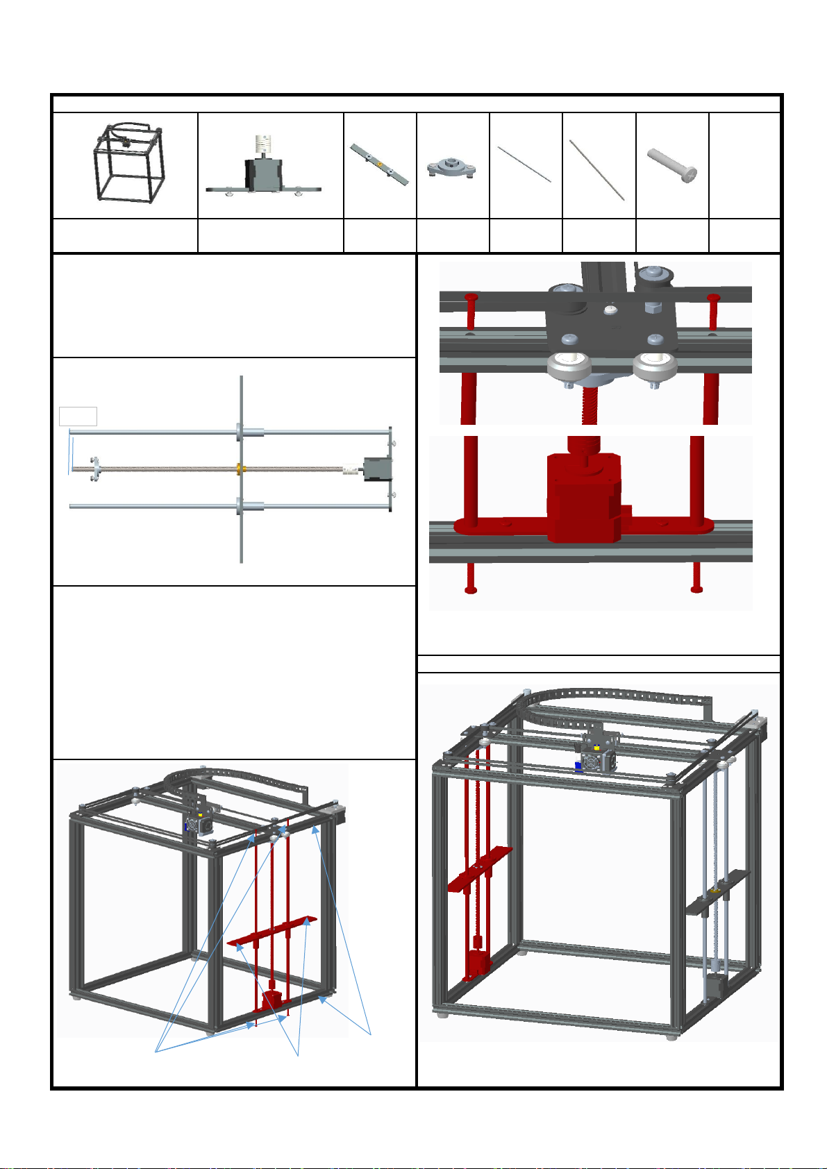
Alu. Profile 2
PM4*20
Sliding rod
Φ8*528 4pcs
Z motor component 2pcs
1.Insert the solid end of the Sliding rod to the hole on Z axis motor holder, insert the barrel of the
motor holder into the hole,do not let the pole stand out,same as the illustration.Then, put the Z
fixed plate component with the pole Φ8*528 together. Thread the the lead screws T8*453 through
the copper nut, connect with the coupling hole on the motor,put the bearing seat component on
lead screw T8*453 same as illustration(The T nuts are at the outer end),then the Z axis carriage
is finished. Total need to assemble 2set.
Lead screw
T8*453 2pcs
Step 7:Assemble Z axis component
Assemble parts specifications and quantity:
Bearing seat
component
2pcs
Screw PM4*20
8pcs
Note:When assemble the pole, keep lead screw T8*453 3mm shorter than sliding rod Φ8*528mm
3.Repeat the number 2,assemble other Z aixs carriage, as the illustration.
Z carriage
2pcs
2.Adjust the T nut on the Z motor component, Place the Z motors to the aluminum
profile 2 , the 2 small M3 holes stand outsite as the illustration. Align sliding rod Φ
8*528 with the hole of the aluminum profile, let screw PM4 * 20 through the holes of
the aluminum profile 2, then connect with the M4 hole of the sliding rod Φ
8*528,same as the illustration, rotate the lead screws T8*453,slide the carriage and
the bearing seat to the top, lock the 2pcs screws PM4*20 to the aluminum profile 2
,then lock the M4 T nut and jackscrew of the bearing seat, rotate the lead screws
T8*453, drop the carriage down,make sure it can move freely. Otherwise, please
loosen the jackscrew,adjust it again. then, lock the 4pcs jackscrew in the coupling , T
nut, screw on the Z motor plate, rotate the lead screw T8*453 again,make sure the Z
carriage can slide up and down freely. finally lock the 2pcs PM4*20 screws from the
bottom of the sliding rods .
Base frame component
1pcs
2 small M3 holes stand outside
3mm

Feeding motor component
Step 8:Assemble feeding motor
2.Place the feeding motor component with 2pcs screw PM4*12 and T
nut M4 ,same as the illustration
1.Put 2pcs screw PM4 * 12mm through the board holder,then lock them with the T
nut M4 screw on the boat nut M4
Assemble parts specifications and quantity:
Main framework
Feeding motor component 1pcs
Screws PM4*12 2pcs
M4 T Nut 2pcs
Screws PM4*12
The heatbed wires exit position The holes
M3 Nut PM4*8 screw
PM3*10 screw
PM3*6 screw
2. Place the towline holder to the metal bar by using screw
PM3*16, same as the illustration
4, Assemble the other end of towline and towline base holder by
using PM3*6mm screws , then secure it to right side of
aluminium profile by using 2pcs PM4*8mm screws, same as the
illustration.
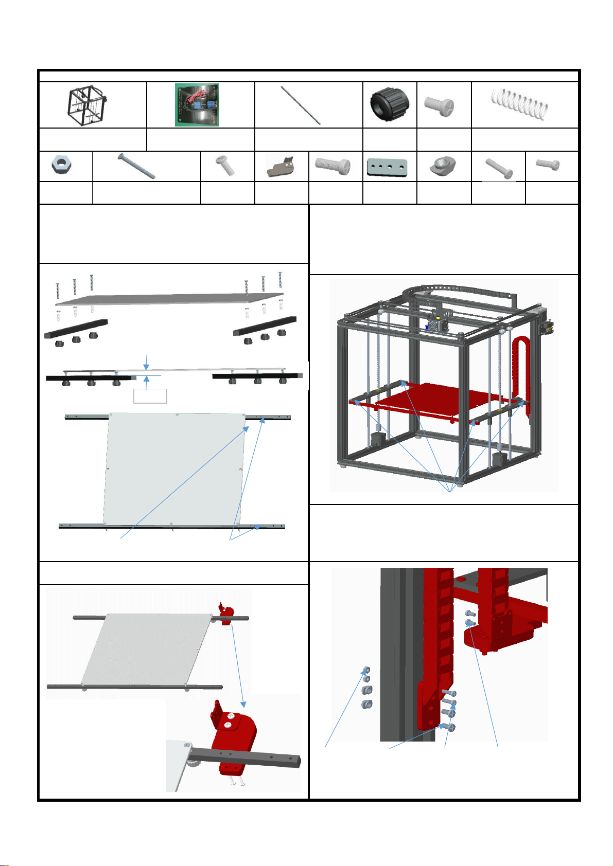
1. Put 6pcs KM3 * 30 screws through the heat bed,then lock them with
the nut M3, same as the illustration,put spring through the KM3 * 30
screws,then, extending from the hole of the metal bar,screw into M3
butterfly nuts, adjust and keep 10 mm between the heat bed and the
metal bar.
3.Rotate 2pcs lead screws T8*453,keep 2 Z carriage at the same plane,
secure the heat bed component and metal bar with 8pcs screw PM4*12.
The towline bracket is close to the side of the feed motor component,
rotate the screw in the same direction,let the platform move up and
down, make sure it can move freely, if not freely, please lossen the
screw PM4*12 to adjust it untill it can move freely
KM3*30 screw 6pcs
PM4*12
screw 8pcs
M4 T nut
2pcs
M3 Nut
8pcs
Towline base
holder 1pcs
Towline
holder 1pcs
PM3*16
screw 2pcs
PM3*10
screw 2pcs
Assemble parts specifications and quantity:
Main framework
Heatbed (with towline)
330x330mm 1pcs
M3 Wing
nut 6pcs
Metal bar 2pcs
Step 9:Assemble printer plateform
PM4*8 screw
2pcs
PM3*6
screw 2pcs
Spring 6pcs
10mm

Note: Please assemble it after wiring . Do not touch the
electronic component by hand for avoiding static electricity.
1.Use 3 PM4*6 screws and 3 T nuts to tighten according to the
map position.
3.Take the power supply module, use 3 PM4*8 screws and 3 hull nuts,
and tighten according to the map position.
2.The main board components are loaded into the lower right
corner of the machine, and are fixed in aluminum grooves with T
nuts.
4.Load the power assembly into the lower right corner of the
machine, and use the T nut to fix it in the aluminum slot.
Screw PM4*6 3pcs
Screw PM4*8 3pcs
Step 10:Assemble electronic board and power supply
Assemble parts specifications and quantity:
Main frame 1pc
Power supply component 1pc
electronic board and touch-screen component 1pc
T nut M4 6pcs

material rack
material rack 1pcs
T nut M4 2pcs
Screw PM4*6 2pcs
1. Pick 1 piece material rack plate, 2 screwsPM4*6, 2 boat nut M4,
assemble as shown.
2. Fix the material rack assembly into the aluminum profile groove with
boat nut, and lock the 2 screws PM4*6, as shown in the figure.(hang the
material plate on the screw rod)
Main framework
Step 11:Assemble feeding holder
Assemble parts specifications and quantity:
Feeding tube
Print platform sticker
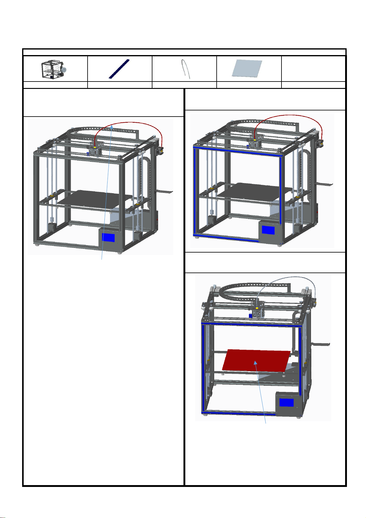
Step 12:Assemble Decorative strip and Feeding tube
Assemble parts specifications and quantity:
1.Put the feeding tube into the hole of the Air cock,insert feeding tube,
press the outer plastic ring of Air cock,loosen the plastic ring,stuck the
feeding tube,same as illustration,move the feeding tube up and down
to make sure it is clenched
2.Align the end seal with the end aluminum profile,then press the seal
into the groove of the aluminum profile,same as illustration.
3, Place the print platform sticker on the heatbed.
Main framework
Aluminium profile seal
Feeding tube 1pcs
Print platform sticker 1pcs

M4 T Nut
2pcs
PM4*8 screws
2pcs
Limit switch (with wires)
1pcs
1. Put 2pcs screw PM4*8 through switch component, then lock
with T nut M4, same as illustration
Step 13:Assemble limit switch
Assemble parts specifications and quantity:
2.Fix switch component in the groove of aluminum profile with
2pcs T nut, then lock 2pcs screw PM4*8,same as the illustration
Main framework

PM4*12
screws 2pcs
M4 T Nut
2pcs
2.Install the filament alarm device in the position shown in the
diagram.To press the end cover into two side aluminum end up and
down.
End cover
1.Put 2pcs screw PM4*12 through cushion plate, then lock with T nut
M4, same as illustration
Main framework
Filament alarm 1pc
End cover 8PCS
Step 14:Assemble Filament alarm
Assemble parts specifications and quantity:

BTEMP
ZSTOP
HOTBED
Power
X-Motor
Y-Motor
Z1-Motor
Z2-Motor
E-Motor
YSTOP
FSTOP
Step 15:Connecting wire
Printing head
Z1-motor
Z2-motor
Y-Motor
X-Motor
E-motor
Heat bed
Printing head The host box
Power
YSTOP
FSTOP

X5SA Physical wiring diagram
F STOP

2. operation instructions
1. Enter the main screen of the startup, display the system and tools, print three main menus, and click on the three sub-menus, as shown in the
figure.Basic functionality for displaying submenus.
2. Click the system menu and enter it into the system submenu, as shown in the figure: click back menu and return to the superior menu.
2.2 click the machine information and display the following figure: display the machine brand, ID, version and other information.Click back menu to
return to the superior menu.
2.3 click the menu to enter Chinese and English.Click back menu to return to the superior menu.
2.1 click the state and display as shown in the figure: display the machine position state parameters.Click back menu to return to the superior menu.

2.4 click factory Settings to ask whether the factory Settings are restored.Click to return to restart and restore the factory Settings.
2.5 click the screen correction icon to enter the screen correction and click the cross position for correction.Adjust the screen when the menu is off, save
it back.
3. Click the tools menu to enter the machine parameter setting and adjustment.
3.1 click the manual menu and enter the manual adjustment mode.Adjust the motor rotation, e. extruder feeding/discharging, XYZ shaft motor moving,
ICONS 0.01mm, 0.1mm, 1mm, 10mm,click on the dark display, such as icon 10mm, each click on the motor stroke moving 10mm.Click the icon and
the machine returns to the origin. icon back to superior menu.

3.2 click the icon of preheating, as shown in the figure, set the heating temperature of the machine extrusion head and the hot bed, heat the icon
hot bed and heat the icon extrusion head, and click the icon in the right and left direction to adjust the setting temperature heating.Use the heating
function when replacing consumables.
3.3 click the icon of loading and unloading consumables to indicate preheating.Remove the consumables to warm up before pulling them out.Set the
heating temperature, the temperature reached, click the icon to return the material.When installing the filaments, make the filaments go straight
out into the hole of the filament run-out detector and press down the feeder's pressing block, as shown in the figure. Pass the filaments through the
feeder to the filaments pipe and then click the icon to send the filaments to the nozzle.Click the icon to stop.
3.4.1 click the leveling icon and enter the leveling menu. There are 3 options: auto leveling, manual leveling and cancel.Click cancel to return.
Other TRONXY 3D Printer manuals

TRONXY
TRONXY X6-2E User manual

TRONXY
TRONXY X3A User manual

TRONXY
TRONXY X5SA-400-2E User manual

TRONXY
TRONXY X5S 2E User manual

TRONXY
TRONXY X5SA-400-PRO User manual

TRONXY
TRONXY X5S User manual

TRONXY
TRONXY P802M User manual

TRONXY
TRONXY XY-3 PRO V2 User manual

TRONXY
TRONXY XY-3 User manual

TRONXY
TRONXY XY-2 PRO User manual

TRONXY
TRONXY X1 User manual

TRONXY
TRONXY VEHO 600-2E User manual

TRONXY
TRONXY D01 User manual

TRONXY
TRONXY VEHO600 User manual

TRONXY
TRONXY X6D User manual

TRONXY
TRONXY XY-2 User manual

TRONXY
TRONXY X5SA-500 User manual

TRONXY
TRONXY Ultrabot User manual

TRONXY
TRONXY X5 User manual

TRONXY
TRONXY XY-2 PRO User manual


