Bartec BACAB FT User manual

Self-regulating trace heating systems
Design Guide
Self-regulating trace heating systems
for roof and gutter de-icing systems in ordinary environments
with BARTEC BACAB FT “black” trace heaters


Table of contents
Overview 2
Technical data 2
Certifications / Approvals 2
Safety 2
Personnel requirements 2
System design 3
Power connection components 4
Trace heater splice / junction components 5
End termination 5
Accessories 6
Trace heater installation 7
Preparation 7
Determination of the trace heater length 7
Maximum heating circuit length 10
Required tools / equipment 11
Unrolling the trace heater 11
Trace heater fixation on gutters 11
Installation of edge protection 12
Trace heater fixation on roofs 13
Placement of connection / splice kits 14
Application of warning labels 14
Tests and commissioning 15
Measurement of the insulation resistance 15
Acceptance test and acceptance test report 15
Commissioning 15
Operation 16
System documentation 16
Maintenance 16
Visual and functional inspection 16
Electrical inspection 16
Inspection intervals 16
Personnel training courses 16
Repairwork on roofs and gutters 16
Troubleshooting 17
Acceptance report 18
Limited product warranty 19

Design Guide
Self-regulating trace heating systems
05-6066-7D0001/A
05/2021-EHT-405838
Notice Technical data subject to change without notice.
No claims for damage arising from alternations, errors or misprints shall be allowed.
Page 2 / 20
Overview
This manual covers the installation and operation of BARTEC Self-
regulating trace heating systems for roof and gutter de-icing using the
following self-regulating trace heaters:
BARTEC BACAB FT “black”;
Typen FT115-1410P (120 V) und FT215-1410P (240 V)
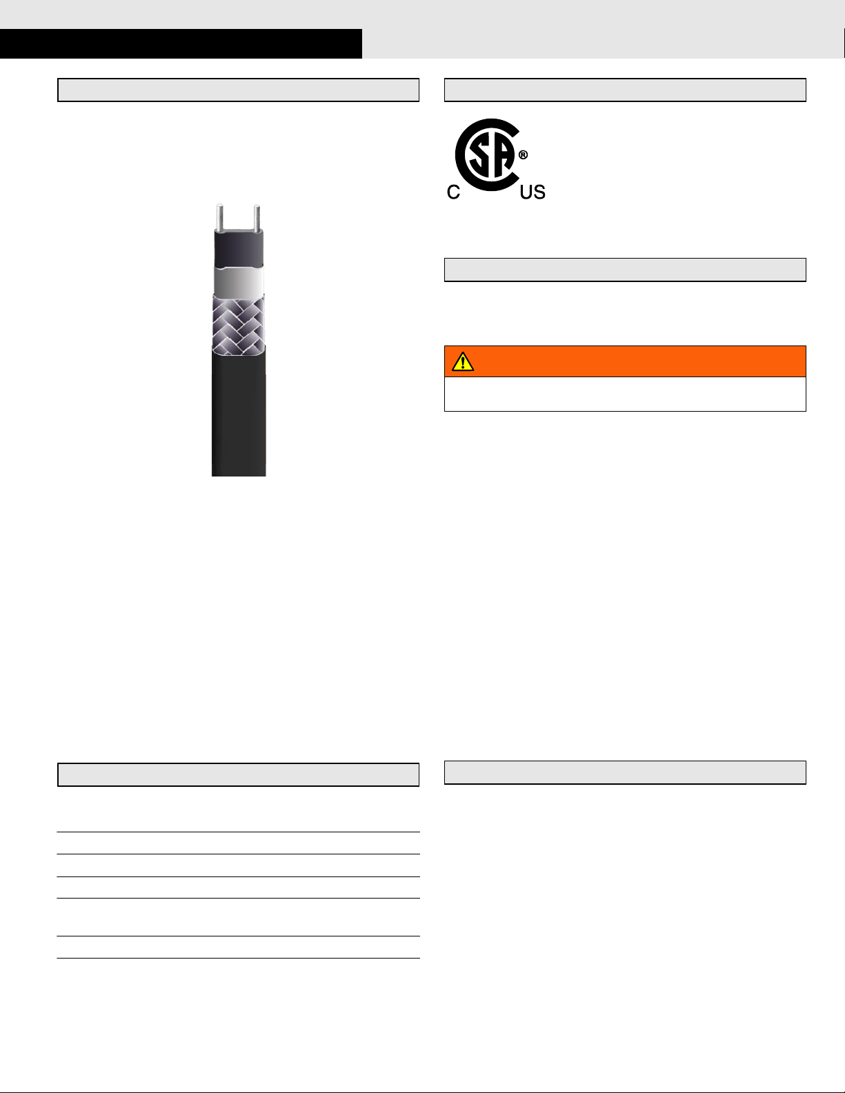
The self-regulating trace heater features a temperature-dependent
resistive heating element between two parallel copper conductors, that
regulates and limits the heat output of the trace heater according to the
ambient temperature. If the ambient temperature rises, the power out-
put of the trace heater is reduced. This self-regulating property prevents
overheating which would cause damage to the trace heater. Even
crossing or overlapping with other trace heaters (or other portions of the
same trace heater) are possible.
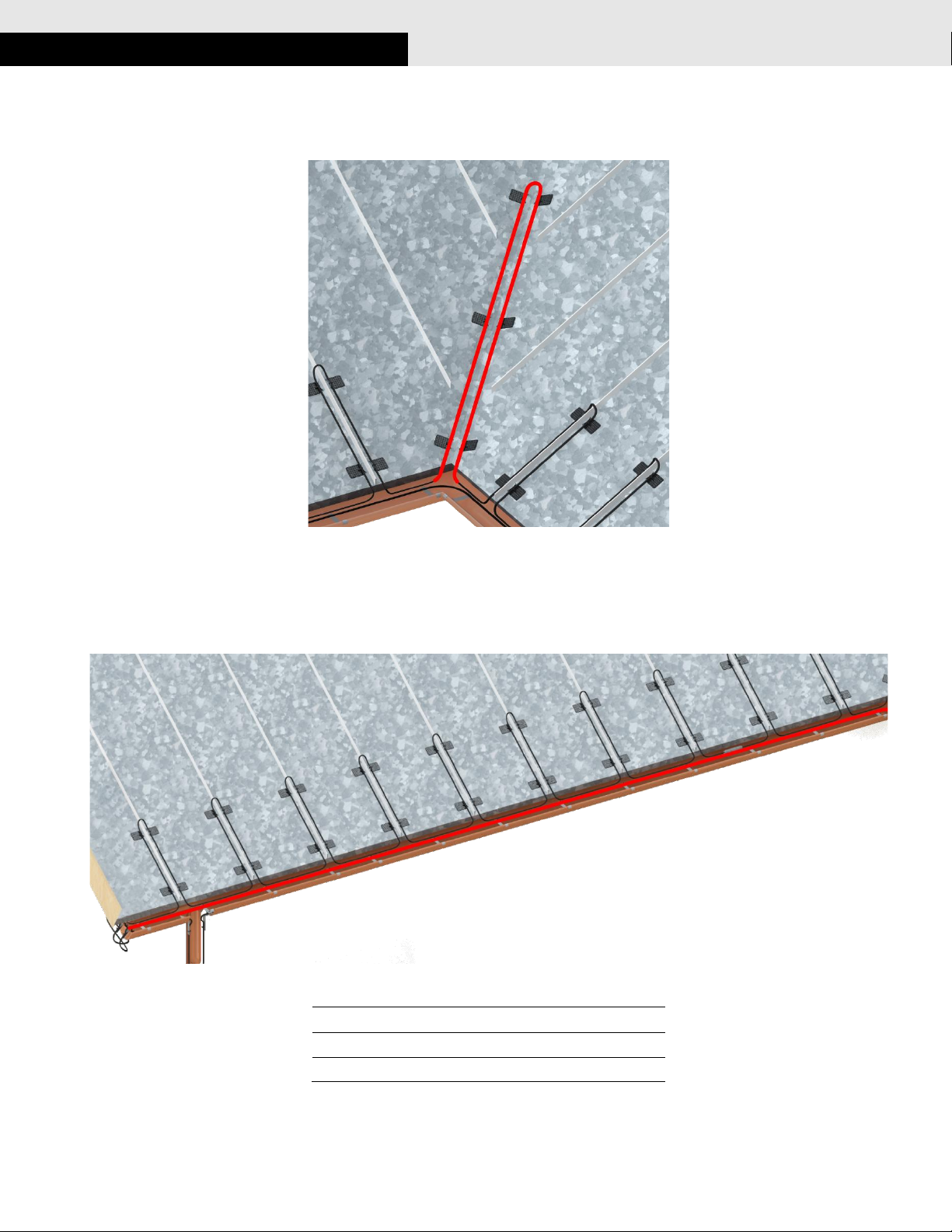
The trace heaters are fixed equipment heating systems for roof and
gutter de-icing in ordinary locations. Thanks to the parallel design the
trace heater can be cut and installed to any required length (up to the
maximum heating circuit length as shown on page 10).
Multiple options for connection, splicing and end termination of the
heating circuit are available to meet the individual requirements on site.
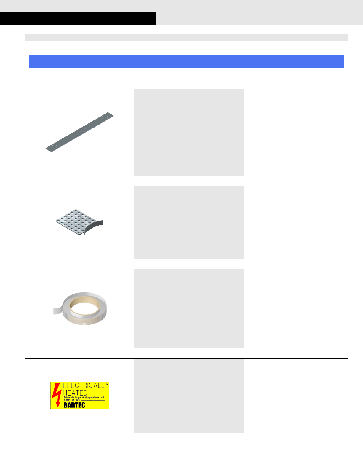
A large variety of accessories allows for easy customization and exten-
sibility.
Technical data
Ambient temperatures
-67 to 185 °F / -55 to 85 °C
(temporary: up to 185 °F / 85 °C)
Operation temperatures
-40 to 150 °F /-40 to 65 °C
Voltage
120 Vac / 208 to 254 Vac
Trace heater output
5 W/ft (15 W/m) @ 50 °F (10 °C)
Resistance of the
grounding braid
< 18.2 Ω/km
Dimensions
0.46” x 0.23” (11.8 x 5.8 mm)
Minimum bending radius
1” (25 mm)
Do not bend on the narrow axis.
Certifications / Approvals
Self-regulating trace heater
BARTEC BACAB FT “black” trace heater for roof and gutter de-icing
Safety
For safe installation and operation of BARTEC Self-regulating trace
heating systems the technical requirements and instructions given in
this manual must be followed.
WARNING
Risk of fire or electrical shock. Follow these guidelines to avoid per-
sonal injury or material damage.
All electrical systems and installations must comply with BARTEC
GmbH requirements and be installed in accordance with the relevant
electrical codes and any other applicable national and local codes.
BARTEC GmbH, the US and Canadian electrical codes require
ground fault protection to be provided for all trace heating circuits.
Install the trace heater circuit carefully.
Use the trace heater in accordance with the intended purpose and
strictly comply with the operational data specified in section Tech-
nical Data.
The bending radius of the trace heater must be at least 1” (25 mm).
Do not bend on the narrow axis.
To avoid short circuits, do not connect the trace heater bus wires
together.
Keep all components and the trace heaters dry before and during
installation.
Each heating circuit must be marked with electrical warning labels
(see Section Accessories on page 6).
Keep these instructions for future reference. If applicable, leave them
with the end user.
De-energize before installation or servicing.
Use only original BARTEC accessories.
Personnel requirements
The personnel executing installation and maintenance tasks must have
acquired the skills and specialized knowledge relating to the types of
protection and types of devices concerned. At least, the personnel must
have:
a general understanding of the relevant electrical engineering
a working knowledge and understanding of the relevant standards for
electrical installations in general and trace heating in particular
a basic knowledge of quality assurance, including the principles of
auditing documentation, traceability of measurements and calibration
of measurement instruments.

05-6066-7D0001/A
05/2021-EHT-405838
Notice Technical data subject to change without notice.
No claims for damage arising from alternations, errors or misprints shall be allowed.
Page 3 / 20
System design
A heating circuit with self-regulating trace heaters usually consists of:
Power supply / cold lead cable connection
Trace heater splices / junctions (optional)
Control and monitoring units (optional)
End termination / end of line lamp
The following figure shows a sample trace heating system including typical components:
The following pages list all compatible components for BARTEC Self-regulating trace heating systems for roof and gutter applications. The respective
installation instructions are included in the scope of delivery.
roof clip
NPT cable gland kit for use
with a 3rd party junction box
trace heater
silicone end seal
TWISTO-N/B splice kit

Design Guide
Self-regulating trace heating systems
05-6066-7D0001/A
05/2021-EHT-405838
Notice Technical data subject to change without notice.
No claims for damage arising from alternations, errors or misprints shall be allowed.
Page 4 / 20
Power connection components
The following components can be used for power connection with BARTEC Self-regulating trace heating systems for roof and gutter applications.
1/2" NPT cable gland kit for use with a 3rd
party junction box (cold applied technology)
For connection of self-regulating trace heaters in
a junction box. Electrical insulation is ensured by
silicone pants for the bus wires and a
green/yellow protection tube for the grounding
conductor.
Catalog No.:
Part No.:
CAK-SRP
27-59CO-32010001
1/2" NPT cable gland kit for use with a 3rd
party junction box (heat shrink technology)
For connection of self-regulating trace heaters in
a junction box. Electrical insulation is ensured by
heat shrink tubes.
Catalog No.:
Part No.:
HSK-SRP
27-59HO-32010001
PSK-S/F-A Heat shrink splice kit
For direct connection of a trace heater to a cold
lead cable. The connection is established using
splice lugs and sealed with heat shrink tubes.
Catalog No.:
PSK-F-A
TWISTO-N/B
power connection, powered splice and
powered T-kits
TWISTO/N-B is a family of connection kits for
self-regulating trace heaters. The TWISTO/N-B
connection kits are simple and safe to use, yet
faster to install and more cost effective than
conventional systems. The connection is estab-
lished using an innovative clamping-sleeve-
technology.
Catalog No.:
TWISTO/N-B-P
(Power connection with cold
lead cable)
TWISTO/N-B-PK
(Power connection with cold
lead cable and end seal)
TWISTO/N-B-PS
(Powered splice kit)
TWISTO/N-B-PT
(Powered T-connection kit)

05-6066-7D0001/A
05/2021-EHT-405838
Notice Technical data subject to change without notice.
No claims for damage arising from alternations, errors or misprints shall be allowed.
Page 5 / 20
Trace heater splice / junction components
The following components can be used for trace heater splices / junctions with BARTEC Self-regulating trace heating systems in ordinary environments.
TSK-F-A Heat shrink splice kit
For direct connection of 2 trace heaters. The
connection is established using splice lugs and
sealed with heat shrink tubes..
Catalog No.:
TSK-F-A
TWISTO-N/B
splice, T- and X-connection kits
TWISTO/N-B is a family of connection kits for
self-regulating trace heaters. The TWISTO/N-B
connection kits are simple and safe to use, yet
faster to install and more cost effective than
conventional systems. The connection is estab-
lished using an innovative clamping-sleeve-
technology.
Catalog No.:
TWISTO/N-B-S
(Splice connection kit)
TWISTO/N-B-PS
(T-connection kit)
TWISTO/N-B-X
(X-connection kit)
End termination
The following components can be used for end termination with BARTEC Self-regulating trace heating systems for roof and gutter applications.
Cold applied end seal
Silicone end seal for insulation of
the end of the trace heater
Catalog No.:
CAK-E10-A
(10 pcs.)
Heat shrinkable end seal
Heat shrinkable end seal for insulation of
the end of the trace heater
Catalog No.:
HSK-E10-A
(10 pcs.)

Design Guide
Self-regulating trace heating systems
05-6066-7D0001/A
05/2021-EHT-405838
Notice Technical data subject to change without notice.
No claims for damage arising from alternations, errors or misprints shall be allowed.
Page 6 / 20
Accessories
The following original BARTEC accessories are available for the BARTEC Self-regulating trace heating systems for roof and gutter applications.
NOTICE
To ensure compliance with the existing technical regulations, use only original accessories from BARTEC. The use of original accessories from
BARTEC is a precondition for the consideration of any warranty claims.
Mounting sheet set
Universal mounting sheets for installation of
trace heaters on gutters or use as an edge
protection. Set including cable ties.
Catalog No
MS-5
(5 mounting sheets,
10 cable ties)
Roof clip set
Roof clips for installation of trace heaters on
roofs
Catalog No
RC-50 / RC25
(only available from BAR-
TEC US)
Adhesive tapes
for trace heater installation on pipes etc.
Catalog No.:
PT-164
(for up to 212 °F / 100 °C)
GT-108
(for up to 356 °F / 180 °C)
Electrical warning label
warning label for trace heater circuits
Catalog No.:
HTWL-DE (German)
HTWL-US (English)
HTWL-FR (French)
HTWL-RU (Russian)

05-6066-7D0001/A
05/2021-EHT-405838
Notice Technical data subject to change without notice.
No claims for damage arising from alternations, errors or misprints shall be allowed.
Page 7 / 20
Trace heater installation
Preparation
Before installing any electric trace heating, the person installing must check if the trace heating has been designed and planned correctly. It is particu-
larly essential to verify the following points:
complete project planning documentation, operating instructions and installation instructions.
correct selection of the trace heater and accessories with respect to:
calculation of heat losses
min. permissible start-up temperature
max. permissible operating temperature
max. permissible ambient temperature
Before installing, make sure that the roof covering, gutters and downspouts are properly installed.
Determination of the trace heater length
The total required trace heater length is determined by the length of the roof, the number of valleys and dimensions of gutters and downspouts:
Step 1: Determine the required trace heater length for the roof.
Standard sloped roofs
Roof overhang
Roof multiplier
12 in (30 cm)
2
24 in (60 cm)
3
36 in (90 cm)
4
length for roofs = roof edge length ×roof multiplier
Standing seam roofs
Roof overhang
Loop height
12 in (30 cm)
24 in (60 cm)
24 in (60 cm)
36 in (90 cm)
36 in (90 cm)
48 in (120 cm)
length for roofs = roof edge length + 2 ×loop height ×no. of seams

Design Guide
Self-regulating trace heating systems
05-6066-7D0001/A
05/2021-EHT-405838
Notice Technical data subject to change without notice.
No claims for damage arising from alternations, errors or misprints shall be allowed.
Page 8 / 20
Step 2: Determine the required trace heater length for valleys.
Snow and ice often accumulate in valleys. The trace heater should be routed up and down the valley to maintain a clear path of melted snow. Add
approximately 6 ft. (180 cm) of heating cable for each valley.
length for valleys = number of valleys × 6 ft. (180 cm)
Step 3: Determine the required trace heater length for gutters.
To allow melted snow and ice to be evacuated, the trace heater must be routed through the gutters. In large gutters, multiple trace heaters are neces-
sary.
Gutter width
Number of trace heaters
< 4 3/4" (12 cm)
1
< 9 1/2" in (24 cm)
2
> 9 1/2" in (24 cm)
3 or more
length for gutters = gutter length × number of trace heaters

05-6066-7D0001/A
05/2021-EHT-405838
Notice Technical data subject to change without notice.
No claims for damage arising from alternations, errors or misprints shall be allowed.
Page 9 / 20
Step 4: Determine the required trace heater length for downspouts.
To allow melted snow and ice to be evacuated, the trace heater must be routed through downspouts (down and up).
NOTICE
If the downspout length exceeds 98 ft. (30 m) you must use a strain
relief to prevent damage to the trace heater.
length for downspouts = 2 × length of all downspouts
Step 5: Determine the total required trace heater length.
Add the calculated lengths of all sections together to obtain the total required trace heater length.
Section
Calculation method
Cable length
Roof
standard sloped roofs:
roof edge length × roof multiplier
standing seam roofs:
roof edge length + 2 × loop height × no. of seams
Valleys
number of valleys × 6 ft. (180 cm)
Gutters
gutter length × number of trace heaters
Downspouts
length of all downspouts × 2
TOTAL REQUIRED LENGTH

Design Guide
Self-regulating trace heating systems
05-6066-7D0001/A
05/2021-EHT-405838
Notice Technical data subject to change without notice.
No claims for damage arising from alternations, errors or misprints shall be allowed.
Page 10 / 20
Maximum heating circuit length
The following table shows the maximum circuit lengths in ft (m) for BARTEC BACAB FT “black” trace heaters for different installation locations with
standard circuit breaker amperages. Breaker sizing should be based on the National Electrical Code, Canadian Electrical Code or any other local or
applicable code. Use only circuit breakers with type C tripping characteristics.
WARNING
Risk of fire, electrical shock or dysfunction.
Observe the maximum amperage of all components of the trace heating circuit. Refer to the installation manual of each of the components for
detailed information.
If the required trace heater length exceeds the maximum heating circuit length you must install multiple heating circuits.
Location
Start-up
temperature
°F (°C)
Maximum heating circuit length in ft. (m) based on circuit breaker sizing
Operating Voltage: 120 Vac
Operating Voltage: 240 Vac
20 A
30 A
40 A
20 A
30 A
40 A
on roofs and val-
leys
+50 (+10)
279 (85)
282 (86)
282 (86)
538 (164)
558 (170)
558 (170)
0 (-18)
200 (61)
282 (86)
282 (86)
387 (118)
558 (170)
558 (170)
-20 (-29)
180 (55)
272 (83)
282 (86)
348 (106)
522 (159)
558 (170)
-40 (-40)
164 (50)
246 (75)
282 (86)
315 (96)
476 (145)
558 (170)
in gutters and
downspouts
ice water
140 (42)
141 (32)
141 (32)
269 (82)
279 (85)
279 (85)

05-6066-7D0001/A
05/2021-EHT-405838
Notice Technical data subject to change without notice.
No claims for damage arising from alternations, errors or misprints shall be allowed.
Page 11 / 20
Required tools / equipment
The following tools are required for installation of the BARTEC Self-
regulating trace heating systems for roof and gutter applications:
Hammer
Cross-head screwdriver
The following protective equipment is required:
Safety gloves
Recommended adhesives for metal roofs:
SpeedBonder ® H3300 (Methacrylate adhesive)
SpeedBonder ® H4800 (Methacrylate adhesive)
Plexus ® MA300 (Methacrylate adhesive)
Plexus ® MA310 (Methacrylate adhesive)
GE ® Grey RTV 167 adhesive (Neutral-cure silicone adhesive)
Unrolling the trace heater
WARNING
Risk of short circuit and/or material damage. Keep the trace heater
ends dry before and during installation.
Unroll the required trace heater in a straight line and cut to the
correct length. Cut off the trace heater ensuring a straight cut.
Do not bend or pinch the trace heater, or pull it over sharp edges.
Trace heater fixation on gutters
CAUTION
Risk of cutting on sharp edges. Wear safety gloves when bending
the mounting sheet.
Bend the mounting sheet in an appropriate shape to clamp it into
the gutter.
1
2
3

Design Guide
Self-regulating trace heating systems
05-6066-7D0001/A
05/2021-EHT-405838
Notice Technical data subject to change without notice.
No claims for damage arising from alternations, errors or misprints shall be allowed.
Page 12 / 20
Feed a UV-resistant cable tie through the mounting sheet.
If necessary, use a hammer to fit the mounting sheet until it firmly
clamps into the gutter.
Attach the trace heater using a UV-resistant cable tie.
Use as many mounting sheets as necessary to ensure proper
fixation of the trace heater.
On large gutters use multiple trace heaters and fix each of them
using the mounting sheets:
Gutters up to approx. 4 3/4" (120 mm) width: single laying
Gutters up to 9 1/2" (240 mm) width: double laying
Gutters over 9 1/2" (240 mm) width: multiple laying
Installation of edge protection
CAUTION
Risk of cutting on sharp edges. Wear safety gloves when handling
the mounting sheet.
Take another mounting sheet and bend it to 90°.
Feed UV-resistant cable ties through the holes of the mounting
sheet.
4
5
6
7

05-6066-7D0001/A
05/2021-EHT-405838
Notice Technical data subject to change without notice.
No claims for damage arising from alternations, errors or misprints shall be allowed.
Page 13 / 20
Install the mounting sheet on the edge of the downspout to provide
mechanical protection and support.
Attach the trace heater using the cable ties.
NOTICE
The bending radius of the trace heater must be at least
1” (25 mm). Do not bend on the narrow axis.
If necessary, use additional mounting sheets to protect the trace
heater from sharp edges.
Trace heater fixation on roofs
Attach the clip to the roof as follows:
For wooden roof laths use nails or screws:
For metal roofs use adhesive
(for adhesive selection refer to step 1 on page 11):
Attach the trace heater to the clip using UV-resistant cable ties.
11
8
9
10

Design Guide
Self-regulating trace heating systems
05-6066-7D0001/A
05/2021-EHT-405838
Notice Technical data subject to change without notice.
No claims for damage arising from alternations, errors or misprints shall be allowed.
Page 14 / 20
Standard sloped roofs
On standard sloped roofs, locate the trace heater in a triangle pattern
according to the following table:
Roof overhang
Loop height
Loop spacing
12 in (30 cm)
18 in (45 cm)
24 in (60 cm)
24 in (60 cm)
30 in (75 cm)
24 in (60 cm)
36 in (90 cm)
42 in (105 cm)
24 in (60 cm)
NOTICE
The bending radius of the trace heater must be at least
1” (25 mm). Do not bend on the narrow axis.
Use as many roof clips as necessary to provide proper fixation of the
trace heater.
Standing seam roofs
On sloped roofs with standing seams, run the trace heater along the
seams according to the following table:
Roof overhang
Loop height
Loop spacing
12 in (30 cm)
24 in (60 cm)
on every seam
24 in (60 cm)
36 in (90 cm)
on every seam
36 in (90 cm)
48 in (120 cm)
on every seam
NOTICE
The bending radius of the trace heater must be at least
1” (25 mm). Do not bend on the narrow axis.
Use as many roof clips as necessary to provide proper fixation of the
trace heater.
Placement of connection / splice kits
All connection / splice kits must be placed in a dry place, e.g.:
under roof overhangs
under gutters
on the edge of the roof gutter
Application of warning labels
Apply electrical warning labels on a clearly visible place.
12B
12A
13
14

05-6066-7D0001/A
05/2021-EHT-405838
Notice Technical data subject to change without notice.
No claims for damage arising from alternations, errors or misprints shall be allowed.
Page 15 / 20
Tests and commissioning
Measurement of the insulation resistance
The measurement of the insulation resistance is used to determine damage to the trace heater and possible installation faults. It must be carried out
at the following times:
Preliminary test (on the reel, before installation of the trace heater on the construction site; refer to Section Acceptance Report on page 18)
Acceptance test (after installation of the heating circuit and before installation of the thermal insulation; refer to Section Acceptance Report on page 18)
Final inspection (immediately after completion of work on the thermal insulation)
Upon commissioning
Before switching on the installation
To do the measurement, proceed as follows:
Use an insulation resistance meter with a minimum testing voltage of 500 Vdc and a maximum testing voltage of 2500 Vdc
(recommended testing voltage: 1500 Vdc, required insulation resistance: > 20 MΩ).
Measure the resistance between each bus wire of the trace heater and the grounding braid.
Measure the resistance between the grounding braid and the earth potential (for this measurement the heating circuit must not be grounded yet).
WARNING
Risk of fire or electrical shock. If the insulation resistance is insufficient you must fix the heating circuit before putting it into operation.
Acceptance test and acceptance test report
After completion of the installation work (before installation of the thermal insulation) each heating circuit must be accepted, if possible in the pres-
ence of the client.
All further tests must also be documented in an acceptance test report (refer to Section Acceptance Report on page 18).
NOTICE
Claims under warranty will not be considered if the acceptance report is not filled in completely.
After completion of work on the thermal insulation final inspection and acceptance of the individual heating circuits is recommended. Usually, this is
the task of the client or the final customer (= final inspection).
Commissioning
Each heat tracing system can only be put into operation if the following conditions are fulfilled:
The acceptance test reports for each heating circuit are complete and the trace heating system has been accepted.
All components of the heating circuit are completely installed and are in working order.
It has been ensured that the heating circuit is operated in conformance with the technical data specified by BARTEC.

Design Guide
Self-regulating trace heating systems
05-6066-7D0001/A
05/2021-EHT-405838
Notice Technical data subject to change without notice.
No claims for damage arising from alternations, errors or misprints shall be allowed.
Page 16 / 20
Operation
During operation of the electric trace heating system you must ensure that all components of the system are operated within the operating data speci-
fied by BARTEC.
This applies particularly to observation of the maximum temperature. Operation within these operating data is a precondition for possible later warran-
ty claims.
System documentation
Complete documentation must be carried out for each system, from the project planning stage, through installation and commissioning up to periodic
maintenance of the trace heating system.
This documentation should include the following:
Project planning documents
Manuals of all of the components of the heating system
Heat loss calculation
Selection of the trace heater
Layout plans with division of heating circuits
Circuit graphs
Acceptance reports
Reports on repair work and any operations carried out on the de-icing system
Inspection reports
Maintenance
Visual and functional inspection
Remove any deposit of leaves, mud etc. from gutters and downspouts.
Regularly check the trace heater for possible damage.
Damaged trace heaters must be replaced.
Parts subject to wear must be replaced (e.g. seals, locking plates etc.).
Check junction boxes, splices, end terminations etc. for corrosion and possible mechanical damage. Make sure that all enclosure covers are
properly in place.
If present, check the temperature controller connecting cables and sensors for damage and that their installation is protected against mechanical
damage.
Electrical inspection
Measurement of the insulation resistance should be seen as a permanent part of regular maintenance. For instructions on how to perform the test
refer to Section Measurement of the insulation resistance on page 15.
Inspection intervals
Inspections should be carried out annually before the heating period begins.
Personnel training courses
Regular maintenance should be carried out by trained, experienced maintenance personnel.
It is recommended that maintenance personnel is updated on new developments in application technology and maintenance.
Repairwork on roofs and gutters
Make sure that all power circuits are de-energized before beginning any repairwork.
Take care that the heat tracing system is not damaged during repairwork on roofs and gutters.
After completion of the repairwork:
Make sure that any repaired heating circuits are properly installed and tested according to the project planning documentation.
WARNING
Risk of fire or electrical shock due to damaged components. Remember that self-regulating trace heaters are designed to be installed only once.
Carry out a visual, functional and electrical test (refer to Section Tests and commissioning on page 15).

05-6066-7D0001/A
05/2021-EHT-405838
Notice Technical data subject to change without notice.
No claims for damage arising from alternations, errors or misprints shall be allowed.
Page 17 / 20
Troubleshooting
Problem
Possible cause
Remedy
Trace heater remains cold
No power supply
Trace heater or cold lead cable not properly
connected
Control unit adjusted incorrectly
Check the supply line
Connect the trace heater and cold lead cable
according to the installation instructions
Adjust the control unit according to the installa-
tion instructions
Automatic circuit breaker disengages
Automatic circuit breaker defective
Automatic circuit breaker has wrong tripping
characteristics, e. g. “B” instead of “C”
Nominal circuit breaker size is insufficient
Maximum heating circuit length has been
exceeded
End seal has not been installed
Short circuit
Humidity inside the connection system or end
seal
Replace the automatic circuit breaker
Install an automatic circuit breaker with Type-C
tripping characteristics
Install an automatic circuit breaker with higher
capacity (Observe the maximum amperage of
all components of the trace heating circuit!)
Split the heating circuit into separate circuits
Install the end seal according to the installation
instructions
Identify the cause and remedy the fault
(e. g. ensure that tape tails are not twisted)
Replace the connection system / end seal
Ground fault protection is disengaged
Trace heater damaged
Moisture in the junction box / connection sys-
tem
Ground fault protection defective
Replace the trace heater at the point where it
is damaged
Dry the junction box / connection system
Be sure that the conduit drain is installed and
breathing properly.
Replace the ground fault protection device(s)

Design Guide
Self-regulating trace heating systems
05-6066-7D0001/A
05/2021-EHT-405838
Notice Technical data subject to change without notice.
No claims for damage arising from alternations, errors or misprints shall be allowed.
Page 18 / 20
Acceptance report
Protocol type
Acceptance test of the heating system
Inspection before commissioning
Maintenance and re-commissioning
Project information
Project
Customer
Heating circuit type
Frost protection on pipes
Roof and gutter de-icing
Temperature maintenance
Visual inspection
Trace heaters
Connection components
Control units
carried out:
____________________________________
Date
_____________________________________
Signature, Company
Functional test
Connect the trace heater to the power supply (a temporary connection to the construction site power supply is also possible). The ground fault protection devices and
automatic circuit breakers must not be triggered. Each heating cable end must be warm after approx. 5 to 10 minutes (test by hand).
carried out:
____________________________________
Date
_____________________________________
Signature, Company
Insulation resistance test
Use an insulation resistance meter with a minimum testing voltage of 500 Vdc and a maximum testing voltage of 2500 Vdc (recommended testing
voltage: 1500 Vdc, required insulation resistance: > 20 MΩ). Measure the resistance between each bus wire of the trace heater and the grounding
braid. Measure the resistance between the grounding braid and the earth potential (for this measurement the heating circuit must not be grounded
yet).
Heating Circuit No.
Trace heater length
_________________ ft. (m)
__________________ ft. (m)
Insulation resistance at ….. V
> __________________ MΩ
> _________________ MΩ
carried out:
____________________________________
Date
_____________________________________
Signature, Company
Remarks: __________________________________________________________________________________________________________________________
___________________________________________________________________________________________________________________________________
___________________________________________________________________________________________________________________________________
____________________________________
City/Date
_____________________________________
Qualified electrician
Name / Signature
_____________________________________
Customer
Name / Signature
NOTICE
Claims under warranty will not be considered if the acceptance report is not filled in completely.
This manual suits for next models
2
Table of contents
Popular Heater manuals by other brands

PAX
PAX TR 45 installation instructions

Convair
Convair CTH01 Owner's instruction manual

Dimplex
Dimplex VERDI manual

Frico
Frico Infrasmart IHS30W/B/S24 Assembly and operating instructions

Dimplex
Dimplex DHCER20WIFI instruction manual

Solar Infra Systems
Solar Infra Systems SIS25M 1848 operating instructions